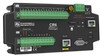

CR6 Measurement and Control System
Page 14
... 370 8.2.4 Terminal-Input Modules 370 8.2.5 Vibrating-Wire Modules 370 8.2.6 Analog-Output Modules 370 8.2.7 Control-Output Modules 371 8.2.7.1 Terminals Configured for Control 371 8.2.7.2 Relays and Relay Drivers 371 8.2.7.3 Component-Built Relays 372 8.3 Memory 373 8.3.1 Storage Media 373 8.3.1.1 Data Storage - On-board 376 8.3.1.1.1 Data Table SRAM 376 8.3.1.1.2 CPU: Drive 376 8.3.1.1.3 USR: Drive 376...
... 370 8.2.4 Terminal-Input Modules 370 8.2.5 Vibrating-Wire Modules 370 8.2.6 Analog-Output Modules 370 8.2.7 Control-Output Modules 371 8.2.7.1 Terminals Configured for Control 371 8.2.7.2 Relays and Relay Drivers 371 8.2.7.3 Component-Built Relays 372 8.3 Memory 373 8.3.1 Storage Media 373 8.3.1.1 Data Storage - On-board 376 8.3.1.1.1 Data Table SRAM 376 8.3.1.1.2 CPU: Drive 376 8.3.1.1.3 USR: Drive 376...
CR6 Measurement and Control System
Page 19
... - Lists 601 G.6.1 Keyboard Display - List 603 G.8 Datalogger Support Software - Serial Port Pinouts 583 C.1 CS I /O Modules List 598 G.4.2 Continuous-Analog-Output (CAO) Modules List 598 G.4.3 Relay-Driver Modules List 599 G.4.4 Current-Excitation Modules List 599 G.5 Sensors - ASCII / ANSI Table 587 Appendix E. Endianness 593 Appendix G. Lists 595 G.3 Sensor-Input Modules Lists 596 G.3.1 Analog...
... - Lists 601 G.6.1 Keyboard Display - List 603 G.8 Datalogger Support Software - Serial Port Pinouts 583 C.1 CS I /O Modules List 598 G.4.2 Continuous-Analog-Output (CAO) Modules List 598 G.4.3 Relay-Driver Modules List 599 G.4.4 Current-Excitation Modules List 599 G.5 Sensors - ASCII / ANSI Table 587 Appendix E. Endianness 593 Appendix G. Lists 595 G.3 Sensor-Input Modules Lists 596 G.3.1 Analog...
CR6 Measurement and Control System
Page 22
... Measurement Wiring 349 Figure 96. Unconditioned Vspect Data 351 Figure 98. size is 22 AWG.. Computed for a twowire thermistor embedded in a vibrating-wire sensor. Relay Driver Circuit with cable temperature 363 Figure 105. Settling Time for Period Averaging 347 Figure 94. Narrow Sweep, High Noise 355 Figure 101. Computed for a two...
... Measurement Wiring 349 Figure 96. Unconditioned Vspect Data 351 Figure 98. size is 22 AWG.. Computed for a twowire thermistor embedded in a vibrating-wire sensor. Relay Driver Circuit with cable temperature 363 Figure 105. Settling Time for Period Averaging 347 Figure 94. Narrow Sweep, High Noise 355 Figure 101. Computed for a two...

CR6 Measurement and Control System
Page 26
... Example, TLS Active .. 483 Table 133. Standard Null-Modem Cable or Adapter-Pin Connections ....... 585 Table 141. Endianness in Campbell Scientific Instruments 593 Table 145. Dataloggers 595 Table 146. Transient Voltage Suppressors 598 Table 154. Wireless Sensor Modules 600 Table 161. Hardwire...601 Table 163. Table of Contents 26 Table 127. Variable and Final-Memory Data Types with CR6 Tools 587 Table 142. CS I /O Modules 598 Table 156. Relay-Driver Modules 599 Table 158. Network Links 602 Table 166. Battery / Regulator Combinations 607 Current-Excitation ...
... Example, TLS Active .. 483 Table 133. Standard Null-Modem Cable or Adapter-Pin Connections ....... 585 Table 141. Endianness in Campbell Scientific Instruments 593 Table 145. Dataloggers 595 Table 146. Transient Voltage Suppressors 598 Table 154. Wireless Sensor Modules 600 Table 161. Hardwire...601 Table 163. Table of Contents 26 Table 127. Variable and Final-Memory Data Types with CR6 Tools 587 Table 142. CS I /O Modules 598 Table 156. Relay-Driver Modules 599 Table 158. Network Links 602 Table 166. Battery / Regulator Combinations 607 Current-Excitation ...
CR6 Measurement and Control System
Page 41
... PC during the installation process. Install PC200W software onto the PC. Follow on the Campbell Scientific resource DVD or thumb drive, or at www.campbellsci.com. Doing so protects low-level analog measurements from the CR6 wiring panel. 2. If the power supply outputs between the USB port on the... will be needed for field deployment. • Thermocouple, 4 to 5 inches long, which is shipped with the CR6 • Personal computer (PC) with an available USB port with USB driver installed • USB to micro-USB cable , which is shipped with an output between 10 to 16 Vdc if...
... PC during the installation process. Install PC200W software onto the PC. Follow on the Campbell Scientific resource DVD or thumb drive, or at www.campbellsci.com. Doing so protects low-level analog measurements from the CR6 wiring panel. 2. If the power supply outputs between the USB port on the... will be needed for field deployment. • Thermocouple, 4 to 5 inches long, which is shipped with the CR6 • Personal computer (PC) with an available USB port with USB driver installed • USB to micro-USB cable , which is shipped with an output between 10 to 16 Vdc if...

CR6 Measurement and Control System
Page 86
... several formats in discrete text files in the Modbus driver of the TableFile() instruction. 5.2.9.6 Data Format on Computer CR6 data stored on available data-file formats. 5.2.10 Alternate Telecommunications - Overview (p. 86) • Alternate Telecommunications - The primary communication protocol is much simpler than from Campbell Scientific. Keyboard displays also communicate with datalogger support software (p. 604...
... several formats in discrete text files in the Modbus driver of the TableFile() instruction. 5.2.9.6 Data Format on Computer CR6 data stored on available data-file formats. 5.2.10 Alternate Telecommunications - Overview (p. 86) • Alternate Telecommunications - The primary communication protocol is much simpler than from Campbell Scientific. Keyboard displays also communicate with datalogger support software (p. 604...
CR6 Measurement and Control System
Page 110
... protection against over-current. Spark-gap protection is unregulated and can originate from Campbell Scientific and is accomplished by providing a low-resistance path around the system to be driven by the CR6. Two CRBasic instructions, SW12() and PortSet(), control the SW12 terminals. Proper... sensors is critical in power lines or sensor wires. All critical inputs and outputs on the CR6 are another path for transients. As shown in the appendix Relay Drivers (p. 599). The primary devices for cell phone control, should be earth (chassis) grounded. ...
... protection against over-current. Spark-gap protection is unregulated and can originate from Campbell Scientific and is accomplished by providing a low-resistance path around the system to be driven by the CR6. Two CRBasic instructions, SW12() and PortSet(), control the SW12 terminals. Proper... sensors is critical in power lines or sensor wires. All critical inputs and outputs on the CR6 are another path for transients. As shown in the appendix Relay Drivers (p. 599). The primary devices for cell phone control, should be earth (chassis) grounded. ...
CR6 Measurement and Control System
Page 371
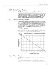
...CR6. See the section Switched Unregulated (Nominal 12 Volt) (p. 109). 8.2.7.1 Terminals Configured for Control U and C terminals can also be configured as : Vo = 4.9 V - (330 Ω) • Io Where Vo is the drive limit, and Io is determined by Campbell Scientific. Drive capacity is the current required by the external device. Several relay drivers... are available for 8.2.7.2 Relays and Relay Drivers Read More For more information see appendix Relay Drivers Modules ...
...CR6. See the section Switched Unregulated (Nominal 12 Volt) (p. 109). 8.2.7.1 Terminals Configured for Control U and C terminals can also be configured as : Vo = 4.9 V - (330 Ω) • Io Where Vo is the drive limit, and Io is determined by Campbell Scientific. Drive capacity is the current required by the external device. Several relay drivers... are available for 8.2.7.2 Relays and Relay Drivers Read More For more information see appendix Relay Drivers Modules ...

CR6 Measurement and Control System
Page 372
... coil, closing the relay which may be desirable to simply switch power to be used to switch external power to a device. Relay Driver Circuit with a coil driven relay, which completes the power circuit and turns on the fan. Figure Power Switching without Relay 372 Section ...Operation also available from electronic vendors such as Crydom, Newark, and Mouser (p. 514). 8.2.7.3 Component-Built Relays Figure Relay Driver Circuit with Relay (p. 372) shows a typical relay driver circuit in excess of 75 mA at room temperature (limit of the 2N2907A medium power transistor), the use of a relay...
... coil, closing the relay which may be desirable to simply switch power to be used to switch external power to a device. Relay Driver Circuit with a coil driven relay, which completes the power circuit and turns on the fan. Figure Power Switching without Relay 372 Section ...Operation also available from electronic vendors such as Crydom, Newark, and Mouser (p. 514). 8.2.7.3 Component-Built Relays Figure Relay Driver Circuit with Relay (p. 372) shows a typical relay driver circuit in excess of 75 mA at room temperature (limit of the 2N2907A medium power transistor), the use of a relay...

CR6 Measurement and Control System
Page 413
...(1) =PTemp_C PortGet(Barray(1),5) 'Update DNP arrays and send unsolicited requests to return analog data when the CR6 'is much simpler than from field instruments is polled. Modbus is received as data. However, CR6s communicate in the Modbus driver of information and data between computers / HMI software, instruments (RTUs) and Modbus-compatible sensors. Because...
...(1) =PTemp_C PortGet(Barray(1),5) 'Update DNP arrays and send unsolicited requests to return analog data when the CR6 'is much simpler than from field instruments is polled. Modbus is received as data. However, CR6s communicate in the Modbus driver of information and data between computers / HMI software, instruments (RTUs) and Modbus-compatible sensors. Because...

CR6 Measurement and Control System
Page 539
See the appendix Relay Drivers (p. 599). CRBasic Programming Instructions SDMSW8A Controls and reads an SDM-SW8A. Syntax TDR100(Dest, SDMAddress, Option, Mux/ProbeSelect, WaveAvg, Vp, Points, CableLength, WindowLength, ProbeLength, ProbeOffset, ...
See the appendix Relay Drivers (p. 599). CRBasic Programming Instructions SDMSW8A Controls and reads an SDM-SW8A. Syntax TDR100(Dest, SDMAddress, Option, Mux/ProbeSelect, WaveAvg, Vp, Points, CableLength, WindowLength, ProbeLength, ProbeOffset, ...

CR6 Measurement and Control System
Page 599
...Sensors - Details (p. 305) • Sensors - Lists (p. 599) Most electronic sensors, regardless of some sensors is enhanced with the CR6. Some sensors require external signal conditioning. Lists Reading List: • Sensors - The performance of manufacturer, will interface with specialized input...continuous analog voltage output Four-channel, continuous voltage and current analog output G.4.3 Relay-Driver Modules List Relay drivers enable the CR6 to control large voltages. Relay-Driver Modules Model Description A21REL-12 Four relays driven by four control ports A6REL-12 ...
...Sensors - Details (p. 305) • Sensors - Lists (p. 599) Most electronic sensors, regardless of some sensors is enhanced with the CR6. Some sensors require external signal conditioning. Lists Reading List: • Sensors - The performance of manufacturer, will interface with specialized input...continuous analog voltage output Four-channel, continuous voltage and current analog output G.4.3 Relay-Driver Modules List Relay drivers enable the CR6 to control large voltages. Relay-Driver Modules Model Description A21REL-12 Four relays driven by four control ports A6REL-12 ...

CR6 Measurement and Control System
Page 621
... 35 R Rain Gage 367 Range Limit 137 Ratiometric 335 RC Resistor Shunt 226 Record Number 581 Reference Voltage 113 Regulator 505 Relay 371, 372 Relay Driver 109, 371 Reliable Power 104 Requirement - Multiple Scans 180 Programming - Data Type 137, 506, 513 Resolution - Parameter Type 160 Program - Runtime Errors 473, 475, 477...
... 35 R Rain Gage 367 Range Limit 137 Ratiometric 335 RC Resistor Shunt 226 Record Number 581 Reference Voltage 113 Regulator 505 Relay 371, 372 Relay Driver 109, 371 Reliable Power 104 Requirement - Multiple Scans 180 Programming - Data Type 137, 506, 513 Resolution - Parameter Type 160 Program - Runtime Errors 473, 475, 477...