
CR9000X Measurement and Control System
Page 5
... Port/ Card Installation QS-2 QS1.4 Powering the Logger QS-3 QS1.5 Setting Up Serial Communications QS-3 QS1.6 Setting Up IP Communications QS-9 QS2. Commonly Used Peripherals OV-22 OV4. Specifications OV-27 1. Installation 1-1 1.1 Enclosure 1-1 1.1.1 Connecting Sensors 1-1 1.1.2 Quick Connectors 1-1 1.1.3 Junction Boxes 1-2 1.2 System Power Requirements and Options 1-3 1.2.1 Power Supply and Charging Circuitry 1-3 1.2.2 Connecting to specific sections. Program Generator Basics QS-12 QS2.1 Program Generator Summary Window QS-12 QS2.2 Program Generator Configuration Window...
... Port/ Card Installation QS-2 QS1.4 Powering the Logger QS-3 QS1.5 Setting Up Serial Communications QS-3 QS1.6 Setting Up IP Communications QS-9 QS2. Commonly Used Peripherals OV-22 OV4. Specifications OV-27 1. Installation 1-1 1.1 Enclosure 1-1 1.1.1 Connecting Sensors 1-1 1.1.2 Quick Connectors 1-1 1.1.3 Junction Boxes 1-2 1.2 System Power Requirements and Options 1-3 1.2.1 Power Supply and Charging Circuitry 1-3 1.2.2 Connecting to specific sections. Program Generator Basics QS-12 QS2.1 Program Generator Summary Window QS-12 QS2.2 Program Generator Configuration Window...
CR9000X Measurement and Control System
Page 41
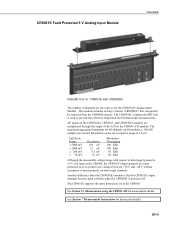
...'s input channels become open switches when the CR9000X is used to data logger ground is ±5 V, the same as the CR9050. All inputs on the CR9050(E), CR9051E, and CR9055(E) modules are faultprotected so as for the CR9050(E) Analog Input Module. OV-9 Another difference from the CR9000X chassis. Resolution on the CR9041 A/D module. The CR9051E supports the same instruction set as...
...'s input channels become open switches when the CR9000X is used to data logger ground is ±5 V, the same as the CR9050. All inputs on the CR9050(E), CR9051E, and CR9055(E) modules are faultprotected so as for the CR9050(E) Analog Input Module. OV-9 Another difference from the CR9000X chassis. Resolution on the CR9041 A/D module. The CR9051E supports the same instruction set as...
CR9000X Measurement and Control System
Page 49
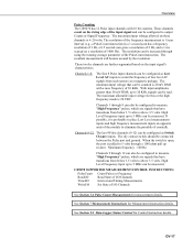
...-17 See Section 9.2 Data Logger Status/ Control for Measurement Instruction details. The resultant measurement will bounce around by the resolution. High Level Frequency input up to output Counts or Signal Frequency. When the switch is open, the port is 20 VDC. The maximum input voltage allowed on the input signal's characteristics. The maximum allowable input voltage for this or the high frequency mode is pulled to...
...-17 See Section 9.2 Data Logger Status/ Control for Measurement Instruction details. The resultant measurement will bounce around by the resolution. High Level Frequency input up to output Counts or Signal Frequency. When the switch is open, the port is 20 VDC. The maximum input voltage allowed on the input signal's characteristics. The maximum allowable input voltage for this or the high frequency mode is pulled to...
CR9000X Measurement and Control System
Page 51
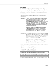
... 20 KHz signals can be connected between the Pulse port and ground. When the switch is open, the port is 25 mV RMS with 32 bit counters. CR9071 SUPPORTED MEASUREMENT/CONTORL INSTRUCTIONS: PulseCount Count Pulses or Frequency ReadI/O Read State of I/O Channels TimerIO Interval and Timing Measurements WaitDigTrig Trigger Measurement Scan WriteI/O Set State of I/O Channels See Section 3.4 Pulse Count Measurements for Control Instruction details...
... 20 KHz signals can be connected between the Pulse port and ground. When the switch is open, the port is 25 mV RMS with 32 bit counters. CR9071 SUPPORTED MEASUREMENT/CONTORL INSTRUCTIONS: PulseCount Count Pulses or Frequency ReadI/O Read State of I/O Channels TimerIO Interval and Timing Measurements WaitDigTrig Trigger Measurement Scan WriteI/O Set State of I/O Channels See Section 3.4 Pulse Count Measurements for Control Instruction details...
CR9000X Measurement and Control System
Page 54
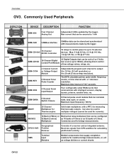
... CAOs updated by the logger. SDM-CD16D 16 Channel Digital Control Port Module 16 Digital Outputs that can be sourced is 1 mA SDM-CAN CANBus interface CANBus data can calculate state, duty cycle, or counts. Maximum time interval of a receiver and an integrated antenna. GPS16-HVS Geographical Position Reciever Consists of 16.7 seconds. Four configurable serial RS232 ports that can be used to 16 external...
... CAOs updated by the logger. SDM-CD16D 16 Channel Digital Control Port Module 16 Digital Outputs that can be sourced is 1 mA SDM-CAN CANBus interface CANBus data can calculate state, duty cycle, or counts. Maximum time interval of a receiver and an integrated antenna. GPS16-HVS Geographical Position Reciever Consists of 16.7 seconds. Four configurable serial RS232 ports that can be used to 16 external...
CR9000X Measurement and Control System
Page 83
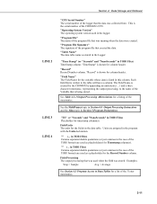
... (or just commas in the program with the Units declaration. "TimeStamp" is being stored. Each field that is shown for a listing of the 3 letter mnemonics. 2-11 LINE 2 LINE 3 LINE 4 Section 2. This is shown for timestamp column(s). "Record" is the serial number of the program file that was used in TOB1 Files) TimeStamp column. "Time Stamp" (or "Seconds" and "NanoSeconds...
... (or just commas in the program with the Units declaration. "TimeStamp" is being stored. Each field that is shown for a listing of the 3 letter mnemonics. 2-11 LINE 2 LINE 3 LINE 4 Section 2. This is shown for timestamp column(s). "Record" is the serial number of the program file that was used in TOB1 Files) TimeStamp column. "Time Stamp" (or "Seconds" and "NanoSeconds...

CR9000X Measurement and Control System
Page 90
...When the input is necessary when working with the polarity programmed and a second measurement is used. One measurement is made with the excitation voltage with high sensor resistances or long lead lengths (higher capacitance). Thus there are not part of the signal. Subtracting...the inputs of the measurement. Delaying between switching to a channel and making the measurement allows the signal to settle to cancel voltage offsets that may vary the sequence and timing of a differential measurement cancels offsets in the sensor, wiring, and measurement circuitry. The default ...
...When the input is necessary when working with the polarity programmed and a second measurement is used. One measurement is made with the excitation voltage with high sensor resistances or long lead lengths (higher capacitance). Thus there are not part of the signal. Subtracting...the inputs of the measurement. Delaying between switching to a channel and making the measurement allows the signal to settle to cancel voltage offsets that may vary the sequence and timing of a differential measurement cancels offsets in the sensor, wiring, and measurement circuitry. The default ...
CR9000X Measurement and Control System
Page 129
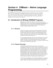
.... Short Cut creates a wiring diagram to simplify connection of predefined measurement, processing, and control algorithms from which to Writing CR9000X Programs Programs are assigned variables (given names). When as much information as a utility in PC200, PC400, LoggerNet, and RTDaq software packages. For many complex applications, one of output data. The program can set-up automatic field calibrations for sensors and set-up trigger conditions...
.... Short Cut creates a wiring diagram to simplify connection of predefined measurement, processing, and control algorithms from which to Writing CR9000X Programs Programs are assigned variables (given names). When as much information as a utility in PC200, PC400, LoggerNet, and RTDaq software packages. For many complex applications, one of output data. The program can set-up automatic field calibrations for sensors and set-up trigger conditions...
CR9000X Measurement and Control System
Page 243
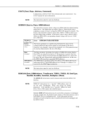
...) 5000 (5000), the SDM-AO4's corresponding channel voltage will be output by each instruction, data is used within a program. Reps Constant SDMAddress Constant The Reps parameter determines the number of the SDM-AO4 that will set using this instruction. If this case, the SDM-AO4s must all use the full voltage range available. See CSAT3 manual for more than four (i.e., voltage is a variable...
...) 5000 (5000), the SDM-AO4's corresponding channel voltage will be output by each instruction, data is used within a program. Reps Constant SDMAddress Constant The Reps parameter determines the number of the SDM-AO4 that will set using this instruction. If this case, the SDM-AO4s must all use the full voltage range available. See CSAT3 manual for more than four (i.e., voltage is a variable...

CR9000X Measurement and Control System
Page 252
.... The INT8 is a four digit code to program the timing functions of the 8 input channels can be placed inside a conditional statement or SubScan. Funct4_1 is addressable using linear interpolation 6 Low resolution frequency (kHz) of edges on this channel 7 Total number of edges on channel 2 between events, frequencies, periods, and/or time since an event. See section 2 of the INT8 manual for one dimensional array...
.... The INT8 is a four digit code to program the timing functions of the 8 input channels can be placed inside a conditional statement or SubScan. Funct4_1 is addressable using linear interpolation 6 Low resolution frequency (kHz) of edges on this channel 7 Total number of edges on channel 2 between events, frequencies, periods, and/or time since an event. See section 2 of the INT8 manual for one dimensional array...
CR9000X Measurement and Control System
Page 360
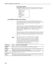
... a specific value. Channels 1thru 6 are Continuous Analog Outputs, channels 7 thru 16 are switched excitation channels. Program Control Instructions Data Statement Examples This example uses Data to hold the data values and Read to transfer the values to read 1, 2, 3, 4 into both X( ) and Y( ) variables. It uses Restore to variables. As long as this task will not be active at the excitation voltage set in a Slow Sequence Scan. Resolution...
... a specific value. Channels 1thru 6 are Continuous Analog Outputs, channels 7 thru 16 are switched excitation channels. Program Control Instructions Data Statement Examples This example uses Data to hold the data values and Read to transfer the values to read 1, 2, 3, 4 into both X( ) and Y( ) variables. It uses Restore to variables. As long as this task will not be active at the excitation voltage set in a Slow Sequence Scan. Resolution...
CR9000X Measurement and Control System
Page 376
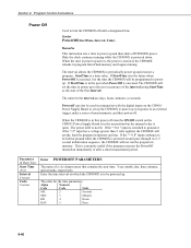
... response to be held at ground while the CR9000X is powered on the CR9011 Power Supply Board to set the time to power up and execute a program. The units for the interval are days, hours, minutes, or seconds. Program Control Instructions Power Off Used to the next occurrence of the interval (using StartTime as the start time: Year, month, day, hour, minutes, and seconds, respectively. Poweroff...
... response to be held at ground while the CR9000X is powered on the CR9011 Power Supply Board to set the time to power up and execute a program. The units for the interval are days, hours, minutes, or seconds. Program Control Instructions Power Off Used to the next occurrence of the interval (using StartTime as the start time: Year, month, day, hour, minutes, and seconds, respectively. Poweroff...
CR9000X Measurement and Control System
Page 426
... processed summaries to internet protocol (IP). The transfer of a particular data table record. Symbol is a proprietary telecommunications protocol similar in Input Storage. on -site. output array a string of Output Processing Instructions include Totalize, Maximize, Minimize, Average, etc. output interval the time interval between Campbell Scientific instrumentation. Examples of data points output to another device. PakBus® is the Greek letter Omega (Ω...
... processed summaries to internet protocol (IP). The transfer of a particular data table record. Symbol is a proprietary telecommunications protocol similar in Input Storage. on -site. output array a string of Output Processing Instructions include Totalize, Maximize, Minimize, Average, etc. output interval the time interval between Campbell Scientific instrumentation. Examples of data points output to another device. PakBus® is the Greek letter Omega (Ω...

CR9000X Measurement and Control System
Page 439
... SDM-CVO4, 7-26 SDMINT8 Interval Timer Instruction, 7-27 SDMIO16 Instruction, 7-30 SDMSIO4 Instruction, 7-31 SDMSpeed Instruction, 7-32 SDMSW8A, 7-31 SDMTrigger Instruction, 7-33 SDMX50, 7-33 SecsSince1990, 9-50 Seebeck Effect, E-8 Select Case, 9-17 Send, E-8 Sensor Calibration File, 9-28 Serial, E-8 Serial Communications Set-up, QS-3 Serial Input/Output, 7-31 Serial Sensor Measurement, 7-42 SerialInput Instruction, 7-42 Server, OV-24 Settling Time, 3-2, 3-8, 3-9 Sgn Function, Sign of Number, 8-33 Short Cut, OV...
... SDM-CVO4, 7-26 SDMINT8 Interval Timer Instruction, 7-27 SDMIO16 Instruction, 7-30 SDMSIO4 Instruction, 7-31 SDMSpeed Instruction, 7-32 SDMSW8A, 7-31 SDMTrigger Instruction, 7-33 SDMX50, 7-33 SecsSince1990, 9-50 Seebeck Effect, E-8 Select Case, 9-17 Send, E-8 Sensor Calibration File, 9-28 Serial, E-8 Serial Communications Set-up, QS-3 Serial Input/Output, 7-31 Serial Sensor Measurement, 7-42 SerialInput Instruction, 7-42 Server, OV-24 Settling Time, 3-2, 3-8, 3-9 Sgn Function, Sign of Number, 8-33 Short Cut, OV...
CR9000X(C) Specifications
Page 1
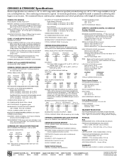
... digital inputs and outputs use gas discharge tubes and transient filters to 18 Vdc TYPICAL CURRENT DRAIN: Base system with an adapter SERIAL INTERFACES: RS-232 9-pin RS-232 DCE port for resistance measurements. CR9011 POWER SUPPLY MODULE VOLTAGE: 9.6 to protect against defects in standby mode by accuracy of reading + 1 A/D counts) -40° to +70°C) INPUT TO SYSTEM GROUND CMRR db: Input Range...
... digital inputs and outputs use gas discharge tubes and transient filters to 18 Vdc TYPICAL CURRENT DRAIN: Base system with an adapter SERIAL INTERFACES: RS-232 9-pin RS-232 DCE port for resistance measurements. CR9011 POWER SUPPLY MODULE VOLTAGE: 9.6 to protect against defects in standby mode by accuracy of reading + 1 A/D counts) -40° to +70°C) INPUT TO SYSTEM GROUND CMRR db: Input Range...
RTDAQ Software
Page 9
Monitoring Data in Real-time 7-1 7.1 Using the Monitor Data Screen 7-1 7.1.1 Connect to Target Datalogger 7-1 7.1.2 Selecting Items for Display in the Monitor Data Screen 7-2 7.1.3 Using the Start/Stop Button 7-3 7.1.4 Customizing the Display of Points per Field 7-34 7.6.2.3 Right-Click Functionality 7-35 7.6.3 Using the Control Buttons 7-36 v RTDAQ Table of Contents 6.9 Printing Options 6-33 6.9.1 Print Setup 6-33 6.9.2 Printing Text 6-34 6.9.3 Printing Graphs 6-34 6.10 View Pro Online Help 6-34 6.11 Assigning Data Files to the...
Monitoring Data in Real-time 7-1 7.1 Using the Monitor Data Screen 7-1 7.1.1 Connect to Target Datalogger 7-1 7.1.2 Selecting Items for Display in the Monitor Data Screen 7-2 7.1.3 Using the Start/Stop Button 7-3 7.1.4 Customizing the Display of Points per Field 7-34 7.6.2.3 Right-Click Functionality 7-35 7.6.3 Using the Control Buttons 7-36 v RTDAQ Table of Contents 6.9 Printing Options 6-33 6.9.1 Print Setup 6-33 6.9.2 Printing Text 6-34 6.9.3 Printing Graphs 6-34 6.10 View Pro Online Help 6-34 6.11 Assigning Data Files to the...
RTDAQ Software
Page 33
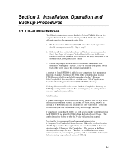
... of your computer's Start menu under C:\Program Files\Campbellsci. The install application should come up automatically. Skip to complete the installation. Trial Version If you will no longer function. The versions in their own directory under Programs | Campbell Scientific | RTDAQ. This activates the RTDAQ Installation Utility. 3. Follow the prompts on the RTDAQ CD and input the CD Key from the back...
... of your computer's Start menu under C:\Program Files\Campbellsci. The install application should come up automatically. Skip to complete the installation. Trial Version If you will no longer function. The versions in their own directory under Programs | Campbell Scientific | RTDAQ. This activates the RTDAQ Installation Utility. 3. Follow the prompts on the RTDAQ CD and input the CD Key from the back...
RTDAQ Software
Page 40
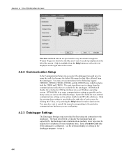
... a Security Code only if the datalogger is provided on the right side of each screen, by clicking the F1 key, or by pressing the Help button for user-entered communications settings such as possible and in the datalogger program - Section 4. via the keyboard/display or settings in many communications settings as phone numbers and RF radio addresses. The next step allows you can use it...
... a Security Code only if the datalogger is provided on the right side of each screen, by clicking the F1 key, or by pressing the Help button for user-entered communications settings such as possible and in the datalogger program - Section 4. via the keyboard/display or settings in many communications settings as phone numbers and RF radio addresses. The next step allows you can use it...
RTDAQ Software
Page 66
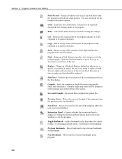
.... Controls whether the Instruction Panel is clicked it on the clipboard to view the program. Cut - Replace - Compile - Moves the cursor to the part of the text. Toggle Bookmark - If a bookmark already exists, it with. Opens a Print Preview screen that allows you to specify a text string to search for and a text string to make sure they should be displayed...
.... Controls whether the Instruction Panel is clicked it on the clipboard to view the program. Cut - Replace - Compile - Moves the cursor to the part of the text. Toggle Bookmark - If a bookmark already exists, it with. Opens a Print Preview screen that allows you to specify a text string to search for and a text string to make sure they should be displayed...

RTDAQ Software
Page 240
..., the data value linked to the component, images used to change made to store RTMC project files. The Preferences menu item opens the Editor Preferences screen used , traces plotted, etc. Section 8. Real-Time Monitoring and Control Software 8.1.4.2 Edit Menu Cut/Copy/Paste are displayed on the type of the menu item, it once to fill the entire computer screen. The box displays information on the screen beside...
..., the data value linked to the component, images used to change made to store RTMC project files. The Preferences menu item opens the Editor Preferences screen used , traces plotted, etc. Section 8. Real-Time Monitoring and Control Software 8.1.4.2 Edit Menu Cut/Copy/Paste are displayed on the type of the menu item, it once to fill the entire computer screen. The box displays information on the screen beside...
