CS135 Lidar Ceilometer
Page 7
...9 4.3 Mounting the CS135 9 4.4 Tilt Angle 10 4.5 Connectors and wiring 12 4.5.1 Base connectors 12 4.5.2 Wiring using supplied Campbell Scientific Cables 13 4.5.3 USB connection 15 4.5.4 SDI-12 connection 15 4.6 Connecting the Back-up Battery 16 4.6.1 Removing the Cover 17 4.6.2 Removing the Enclosure Lid 17 4.7 Storage Information 18 Section 5. General Information 1 1.1 Manual Version 1 1.2 General Safety 1 1.3 Sensor Unit Safety 1 1.4 Laser Safety 2 1.5 Electrical Safety 2 Section 2. Contents PDF viewers note: These page numbers refer to specific sections. Use the Adobe...
...9 4.3 Mounting the CS135 9 4.4 Tilt Angle 10 4.5 Connectors and wiring 12 4.5.1 Base connectors 12 4.5.2 Wiring using supplied Campbell Scientific Cables 13 4.5.3 USB connection 15 4.5.4 SDI-12 connection 15 4.6 Connecting the Back-up Battery 16 4.6.1 Removing the Cover 17 4.6.2 Removing the Enclosure Lid 17 4.7 Storage Information 18 Section 5. General Information 1 1.1 Manual Version 1 1.2 General Safety 1 1.3 Sensor Unit Safety 1 1.4 Laser Safety 2 1.5 Electrical Safety 2 Section 2. Contents PDF viewers note: These page numbers refer to specific sections. Use the Adobe...
CS135 Lidar Ceilometer
Page 8
... 7.5 Diagnostic LED Indicators Within the Enclosure 60 7.6 Electrical Safety Testing 61 Figures 2-1. Mounting footprint 10 4-2. USB port 16 4-6. Manual revisions 1 4-1. CS135 Ceilometer 3 2-2. Connector layout 12 4-4. LED indicator 29 7-1. Removing the enclosure lid 17 5-1. Summary of the connector pins 13 5-1. 5.3 LED Indicator 29 Section 6. Setting the tilt angle 11 4-3. Cable Connections 15 4-5. Removing the enclosure lid 59 7-3. Diagnostic LED indicators 60 Tables...
... 7.5 Diagnostic LED Indicators Within the Enclosure 60 7.6 Electrical Safety Testing 61 Figures 2-1. Mounting footprint 10 4-2. USB port 16 4-6. Manual revisions 1 4-1. CS135 Ceilometer 3 2-2. Connector layout 12 4-4. LED indicator 29 7-1. Removing the enclosure lid 17 5-1. Summary of the connector pins 13 5-1. 5.3 LED Indicator 29 Section 6. Setting the tilt angle 11 4-3. Cable Connections 15 4-5. Removing the enclosure lid 59 7-3. Diagnostic LED indicators 60 Tables...

CS135 Lidar Ceilometer
Page 9
... user to dangerous light levels and voltages. 1 Ignoring these cautions could result in the installation, use of the CS135. WARNING Do not modify the CS135 unit. Ignoring these warnings could result in order to the sensor unit. CS135 Ceilometer 1. These should be followed carefully in the sensor being damaged and data being lost. General Information 1.1 Manual Version Table 1.1 Manual revisions Manual Version 1.0 Applicable to Operating...
... user to dangerous light levels and voltages. 1 Ignoring these cautions could result in the installation, use of the CS135. WARNING Do not modify the CS135 unit. Ignoring these warnings could result in order to the sensor unit. CS135 Ceilometer 1. These should be followed carefully in the sensor being damaged and data being lost. General Information 1.1 Manual Version Table 1.1 Manual revisions Manual Version 1.0 Applicable to Operating...
CS135 Lidar Ceilometer
Page 10
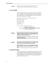
...For permanent installations outside of the housing. WARNING Check that the laser warning label on an annual basis. This is an embedded laser where the output from potentially hazardous mains voltages the wiring of the ...output has the following warning: INVISIBLE LASER RADIATION DO NOT VIEW DIRECTLY WITH OPTICAL INSTRUMENTS CLASS 1M LASER PRODUCT WARNING Removing the laser module with the power applied to the CS135 or battery connected may expose the user to hazardous class 3B laser radiation. This classification indicates that viewing of its power supply should be made to operate...
...For permanent installations outside of the housing. WARNING Check that the laser warning label on an annual basis. This is an embedded laser where the output from potentially hazardous mains voltages the wiring of the ...output has the following warning: INVISIBLE LASER RADIATION DO NOT VIEW DIRECTLY WITH OPTICAL INSTRUMENTS CLASS 1M LASER PRODUCT WARNING Removing the laser module with the power applied to the CS135 or battery connected may expose the user to hazardous class 3B laser radiation. This classification indicates that viewing of its power supply should be made to operate...
CS135 Lidar Ceilometer
Page 12
...frequency filters to fall below 2,000 m. CS135 Ceilometer 2.1 Introduction The CS135 is range corrected. The signal amplitude is a LIDAR (LIght Detection And Ranging...using thresholds based upon changes in the strength of likely cloud bases. The variation in slope of 1000m. Close range signal distortion is removed (the signal response is given as follows: - This results in a number of possible cloud bases at least a set of the backscattered light signal...detected the CS135 will not be calculated. After the scatter coefficient has fallen below the threshold a new cloud base ...
...frequency filters to fall below 2,000 m. CS135 Ceilometer 2.1 Introduction The CS135 is range corrected. The signal amplitude is a LIDAR (LIght Detection And Ranging...using thresholds based upon changes in the strength of likely cloud bases. The variation in slope of 1000m. Close range signal distortion is removed (the signal response is given as follows: - This results in a number of possible cloud bases at least a set of the backscattered light signal...detected the CS135 will not be calculated. After the scatter coefficient has fallen below the threshold a new cloud base ...

CS135 Lidar Ceilometer
Page 13
... under laser output level. Data messages, see Fig 2.2). User Guide The control system of the CS135 is divided into a compact package (see Section 5, include this information allowing remote diagnosis of the CS135 condition. PSU controls the power supply, including battery charging and deep...number of safety shutdown features such as follows:DSP is incorporated to allow measurements at close ranges. 2.3 Internal Monitoring The CS135 monitors a large number of operation 2.2 Optical Measurement 2.2.1 Optical Arrangement The CS135 employs a novel split-lens design to increase optical signal...
... under laser output level. Data messages, see Fig 2.2). User Guide The control system of the CS135 is divided into a compact package (see Section 5, include this information allowing remote diagnosis of the CS135 condition. PSU controls the power supply, including battery charging and deep...number of safety shutdown features such as follows:DSP is incorporated to allow measurements at close ranges. 2.3 Internal Monitoring The CS135 monitors a large number of operation 2.2 Optical Measurement 2.2.1 Optical Arrangement The CS135 employs a novel split-lens design to increase optical signal...
CS135 Lidar Ceilometer
Page 14
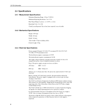
... when connected to generators or when the power factor of your supply is specified at the time of the CS135 may be changed later please contact Campbell Scientific for both 115 VAC and 230 VAC. The internal heater requires a maximum of 270 W. In cold environments the power consumption of order. Fuses: The power supply contains two fuses as follows: AUX fuse HBC 5 A (T) PSU fuse HBC...
... when connected to generators or when the power factor of your supply is specified at the time of the CS135 may be changed later please contact Campbell Scientific for both 115 VAC and 230 VAC. The internal heater requires a maximum of 270 W. In cold environments the power consumption of order. Fuses: The power supply contains two fuses as follows: AUX fuse HBC 5 A (T) PSU fuse HBC...
CS135 Lidar Ceilometer
Page 16
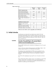
... LED visible from above should now be outputting message type 001 every 10 seconds (see Section 6.2). The CS135 will be set to use date/time information this port number. Maximum voltage at any direction where it could be checked as the battery is connected. USB Service Port USB1.1 and 2.0 compatible, fixed 115200 baud. +0.2V 5V +7V 3. Connect the hood heater plug once you have done these you...
... LED visible from above should now be outputting message type 001 every 10 seconds (see Section 6.2). The CS135 will be set to use date/time information this port number. Maximum voltage at any direction where it could be checked as the battery is connected. USB Service Port USB1.1 and 2.0 compatible, fixed 115200 baud. +0.2V 5V +7V 3. Connect the hood heater plug once you have done these you...
CS135 Lidar Ceilometer
Page 17
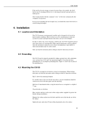
... the back-up battery or mains power. User Guide If the unit has been in storage or transit for more than a few considerations to take care that the orientation allows tilting in areas where contamination is designed to an adequate grounding point. Close terminal mode with the unit, the CS135 should be located in harsh weather conditions. In order...
... the back-up battery or mains power. User Guide If the unit has been in storage or transit for more than a few considerations to take care that the orientation allows tilting in areas where contamination is designed to an adequate grounding point. Close terminal mode with the unit, the CS135 should be located in harsh weather conditions. In order...
CS135 Lidar Ceilometer
Page 21
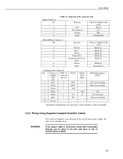
... the power cable is incorrectly wired then irrevocable damage can be connected together. 4.5.2 Wiring Using Supplied Campbell Scientific Cables Two cables are supplied, each 10m long. User Guide Mains Connector Pin 1 2 3 4 Table 4.1 Function of the connector pins Function Live Not connected Neutral Earth Colour of supplied cable cores Brown NA Blue Green/yellow Blower/Heater Connector Pin 1 2 3 4 5 6 E Function Neutral Fan + Therm Therm (0V) Switched 230/115 AC Live Fan on Earth Colour of supplied cable cores Black (1) Black (2) Black (3) Black (4) Black (5) Black (6) Green...
... the power cable is incorrectly wired then irrevocable damage can be connected together. 4.5.2 Wiring Using Supplied Campbell Scientific Cables Two cables are supplied, each 10m long. User Guide Mains Connector Pin 1 2 3 4 Table 4.1 Function of the connector pins Function Live Not connected Neutral Earth Colour of supplied cable cores Brown NA Blue Green/yellow Blower/Heater Connector Pin 1 2 3 4 5 6 E Function Neutral Fan + Therm Therm (0V) Switched 230/115 AC Live Fan on Earth Colour of supplied cable cores Black (1) Black (2) Black (3) Black (4) Black (5) Black (6) Green...
CS135 Lidar Ceilometer
Page 22
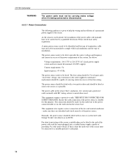
... sensor as an RCD). The power source needs to be able to help the wiring and installation of the system. Voltage requirements: 106-137V or 216-253V AC (check power supply switch and fuses match the nominal 115/230V supply) Current requirements: 5A Input frequency: 47-63 Hz. This equipment requires a protective earth. Ensure the earth connection at the power source. This equipment also...
... sensor as an RCD). The power source needs to be able to help the wiring and installation of the system. Voltage requirements: 106-137V or 216-253V AC (check power supply switch and fuses match the nominal 115/230V supply) Current requirements: 5A Input frequency: 47-63 Hz. This equipment requires a protective earth. Ensure the earth connection at the power source. This equipment also...
CS135 Lidar Ceilometer
Page 23
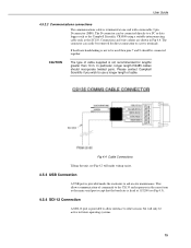
... connected directly to a PC or data logger such as the Campbell Scientific CR1000 using a suitable interconnecting cable such as the main serial port except that the baud rate is fixed at one end with a removable 9 pin D-connector (DB9). This allows communication of cable. If hardware handshaking is provided to allow interface to other sensors but will make wiring easier. 4.5.3 USB Connection A USB port is not recommended for direct connection...
... connected directly to a PC or data logger such as the Campbell Scientific CR1000 using a suitable interconnecting cable such as the main serial port except that the baud rate is fixed at one end with a removable 9 pin D-connector (DB9). This allows communication of cable. If hardware handshaking is provided to allow interface to other sensors but will make wiring easier. 4.5.3 USB Connection A USB port is not recommended for direct connection...
CS135 Lidar Ceilometer
Page 27
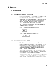
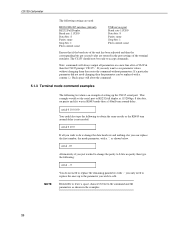
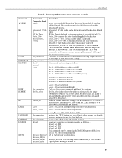
... a summary of the terminal mode commands available. Operation 5.1 Terminal mode 5.1.1 Entering/Exiting the CS135 Terminal Mode The menu system is set up the unit. User Guide 5. The following the command are case sensitive. The CS135 Commands are sent. Example of the "open command with this requires XMODEM protocol. The terminal emulators built into many Campbell Scientific software products can be setup and controlled by the parameter...
... a summary of the terminal mode commands available. Operation 5.1 Terminal mode 5.1.1 Entering/Exiting the CS135 Terminal Mode The menu system is set up the unit. User Guide 5. The following the command are case sensitive. The CS135 Commands are sent. Example of the "open command with this requires XMODEM protocol. The terminal emulators built into many Campbell Scientific software products can be setup and controlled by the parameter...
CS135 Lidar Ceilometer
Page 28
... value are used: RS232/422/485 interface (default) RS232 Full Duplex Baud rate: 115200 Data bits: 8 Parity: none Stop bits: 1 Flow control: none USB service port Baud: rate 115200 Data bits: 8 Parity: none Stop bits: 1 Flow control: none Ensure that if the baud rate of the terminal emulator. If a particular parameter did not need to replace the ones up the CS135 serial port. If...
... value are used: RS232/422/485 interface (default) RS232 Full Duplex Baud rate: 115200 Data bits: 8 Parity: none Stop bits: 1 Flow control: none USB service port Baud: rate 115200 Data bits: 8 Parity: none Stop bits: 1 Flow control: none Ensure that if the baud rate of the terminal emulator. If a particular parameter did not need to replace the ones up the CS135 serial port. If...
CS135 Lidar Ceilometer
Page 29
... power up a list of the sensor beyond which an alarm will be used lower case letters are not allowed. Instructs the CS135 to try and turn the laser off Laser = 1, laser heater on Loads new operating system into modules as follows:- Message_Interval is the offset to turn the laser on (default) Calls up (default). Noise_Gate = -1000, all back scatter range is range corrected. If set...
... power up a list of the sensor beyond which an alarm will be used lower case letters are not allowed. Instructs the CS135 to try and turn the laser off Laser = 1, laser heater on Loads new operating system into modules as follows:- Message_Interval is the offset to turn the laser on (default) Calls up (default). Noise_Gate = -1000, all back scatter range is range corrected. If set...
CS135 Lidar Ceilometer
Page 30
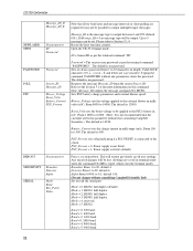
... 999 (default 001). Resets the laser run time counter. ID = Sensor ID as per the terminal command "ID" Password = The sensors user password as per the terminal command "PASSWORD". Sets PSU battery charge parameters and external blower speed. The default is 12000. Mode = 1, RS232, half duplex. Mode = 2, RS485, full duplex. Baud = 5, 9600 baud. 22 Typing the command PASSWORD without consulting Campbell Scientific Ltd) Set or read the serial port Mode...
... 999 (default 001). Resets the laser run time counter. ID = Sensor ID as per the terminal command "ID" Password = The sensors user password as per the terminal command "PASSWORD". Sets PSU battery charge parameters and external blower speed. The default is 12000. Mode = 1, RS232, half duplex. Mode = 2, RS485, full duplex. Baud = 5, 9600 baud. 22 Typing the command PASSWORD without consulting Campbell Scientific Ltd) Set or read the serial port Mode...

CS135 Lidar Ceilometer
Page 31
...=hours, mm=minutes, ss=seconds (i.e. Baud = 8, 57600 baud. Range 0-1000mS, default 100mS. Outputs CS135, serial number, DSP OS version, TOP OS version, PSU OS version, time & date, blower heater mode, internal heater mode, serial parameters, message parameters, tilt angle, units, temperature/humidity, hood temperature, height offset, alarms, warnings, PSU voltage and backup battery voltage. Units = 0, metres corrected by tilt. 5.1.4 MCFG command message types The...
...=hours, mm=minutes, ss=seconds (i.e. Baud = 8, 57600 baud. Range 0-1000mS, default 100mS. Outputs CS135, serial number, DSP OS version, TOP OS version, PSU OS version, time & date, blower heater mode, internal heater mode, serial parameters, message parameters, tilt angle, units, temperature/humidity, hood temperature, height offset, alarms, warnings, PSU voltage and backup battery voltage. Units = 0, metres corrected by tilt. 5.1.4 MCFG command message types The...
CS135 Lidar Ceilometer
Page 34
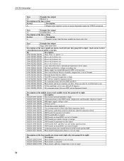
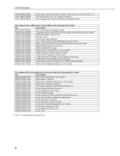
... DSP factory calibration stored in feet or metres dependent upon the UNITS command Line Example line output 16 LaserRunDays A Description of the line sections Section Description A Number of days that the laser module has been active for future use 0400 XXXX XXXX Laser shut down due to operating temperature out of range 0200 XXXX XXXX The lead acid battery...
... DSP factory calibration stored in feet or metres dependent upon the UNITS command Line Example line output 16 LaserRunDays A Description of the line sections Section Description A Number of days that the laser module has been active for future use 0400 XXXX XXXX Laser shut down due to operating temperature out of range 0200 XXXX XXXX The lead acid battery...
CS135 Lidar Ceilometer
Page 39
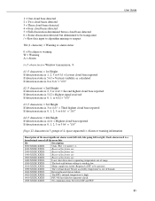
...). User Guide 1 = One cloud base detected 2 = Two cloud bases detected 3 = Three cloud bases detected 4 = Four cloud bases detected 5 = Full obscuration determined but no cloud base detected 6 = Some obscuration detected but determined to be transparent / = Raw data input to algorithm missing or suspect WA (1 character) = Warning or alarm status: 0 = No alarm or warning W = Warning A = Alarm tr (3 characters) = Window transmission...
...). User Guide 1 = One cloud base detected 2 = Two cloud bases detected 3 = Three cloud bases detected 4 = Four cloud bases detected 5 = Full obscuration determined but no cloud base detected 6 = Some obscuration detected but determined to be transparent / = Raw data input to algorithm missing or suspect WA (1 character) = Warning or alarm status: 0 = No alarm or warning W = Warning A = Alarm tr (3 characters) = Window transmission...
CS135 Lidar Ceilometer
Page 40
CS135 Ceilometer 0004 XXXX XXXX 0002 XXXX XXXX 0001 XXXX XXXX Photo diode and Laser windows are not within specifications XXXX 0004 XXXX TOP boards on XXXX XXXX 0040 Laser did not achieve significant output power XXXX XXXX 0020 Laser max power exceeded XXXX XXXX 0010 Laser max drive current exceeded XXXX XXXX 0008 Laser power... XXXX DSP input supply voltage is low XXXX 1000 XXXX Self-test active XXXX 0800 XXXX Watch dog counter updated XXXX 0400 XXXX User setting stored in flash failed their signature checks XXXX 0200 XXXX DSP factory calibration stored in flash has failed...
CS135 Ceilometer 0004 XXXX XXXX 0002 XXXX XXXX 0001 XXXX XXXX Photo diode and Laser windows are not within specifications XXXX 0004 XXXX TOP boards on XXXX XXXX 0040 Laser did not achieve significant output power XXXX XXXX 0020 Laser max power exceeded XXXX XXXX 0010 Laser max drive current exceeded XXXX XXXX 0008 Laser power... XXXX DSP input supply voltage is low XXXX 1000 XXXX Self-test active XXXX 0800 XXXX Watch dog counter updated XXXX 0400 XXXX User setting stored in flash failed their signature checks XXXX 0200 XXXX DSP factory calibration stored in flash has failed...
