Service Manual
Page 4
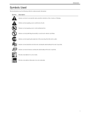
... item intended to provide notes assisting the understanding of a non-specific nature, possibly classified as Note, Caution, or Warning. Provides a description of the nature of a service mode. Introduction i
... item intended to provide notes assisting the understanding of a non-specific nature, possibly classified as Note, Caution, or Warning. Provides a description of the nature of a service mode. Introduction i

Service Manual
Page 14
...- 2 13.3.2 User Error Code ...13- 3 13.3.2.1 User Error Code ...13- 3 13.3.3 Service Error Code...13- 3 13.3.3.1 Service Error Code ...13- 3 Chapter 14 Service Mode 14.1 Outline ...14- 1 14.1.1 Outline of Service Mode ...14- 1 14.1.2 Using the Mode ...14- 2 14.2 Default Settings...14- 2 14.2.1 Service Mode Menus ...14- 2 14.3 Service Soft Switch Settings (SSSW) ...14- 8 14.3.1 Outline ...14- 8 14.3.1.1 Bit Switch...
...- 2 13.3.2 User Error Code ...13- 3 13.3.2.1 User Error Code ...13- 3 13.3.3 Service Error Code...13- 3 13.3.3.1 Service Error Code ...13- 3 Chapter 14 Service Mode 14.1 Outline ...14- 1 14.1.1 Outline of Service Mode ...14- 1 14.1.2 Using the Mode ...14- 2 14.2 Default Settings...14- 2 14.2.1 Service Mode Menus ...14- 2 14.3 Service Soft Switch Settings (SSSW) ...14- 8 14.3.1 Outline ...14- 8 14.3.1.1 Bit Switch...
Service Manual
Page 69
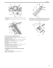
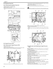
... the Additional functions key, 2 key, 8 key, and Additional functions key on the operation panel. 2) Press the arrow key on the touch panel to display "TEST MODE". 3) Press [OK]. 4) Press the [2] key to display "SCAN TEST". 5) Press the [1] key to break the hook, remove the home position sensor [1] with a flathead screwdriver. After... after Replacing the CS 0012-7426 After replacing the contact sensor (CS), go through the following steps to perform inter-channel output correction: 1) Enter the service mode.
... the Additional functions key, 2 key, 8 key, and Additional functions key on the operation panel. 2) Press the arrow key on the touch panel to display "TEST MODE". 3) Press [OK]. 4) Press the [2] key to display "SCAN TEST". 5) Press the [1] key to break the hook, remove the home position sensor [1] with a flathead screwdriver. After... after Replacing the CS 0012-7426 After replacing the contact sensor (CS), go through the following steps to perform inter-channel output correction: 1) Enter the service mode.
Service Manual
Page 81
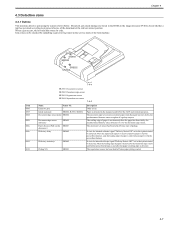
.... 4-7 Jam codes can be detected, when the leading edge of the document at the relevant sensor position. Document jam check timings are stored in the service mode of a pickup request. Chapter 4 4.3 Detection Jams 4.3.1 Outline 0011-5776 This machine detects a jam using the sensors shown below. When a jam occurs, the host machine stores...
.... 4-7 Jam codes can be detected, when the leading edge of the document at the relevant sensor position. Document jam check timings are stored in the service mode of a pickup request. Chapter 4 4.3 Detection Jams 4.3.1 Outline 0011-5776 This machine detects a jam using the sensors shown below. When a jam occurs, the host machine stores...
Service Manual
Page 146
...procedure, the contact sensor output is compensated and parameters are set automatically. After completion of output between CS channels 1) Enter the service mode. Sequentially press the Additional functions key, 2 key, 8 key, and Additional functions key on the operation panel. 2) Press ... key on the touch panel to display "TEST MODE". 3) Press [OK]. 4) Press the [2] key to display "SCAN TEST". 5) Press the [1] key to display "TEST MODE". After completion of automatic adjustment, "OK" is installed) 1) Enter the service mode. Chapter 9 9.4.5 Operation Panel Unit 9.4.5.1 Removing the...
...procedure, the contact sensor output is compensated and parameters are set automatically. After completion of output between CS channels 1) Enter the service mode. Sequentially press the Additional functions key, 2 key, 8 key, and Additional functions key on the operation panel. 2) Press ... key on the touch panel to display "TEST MODE". 3) Press [OK]. 4) Press the [2] key to display "SCAN TEST". 5) Press the [1] key to display "TEST MODE". After completion of automatic adjustment, "OK" is installed) 1) Enter the service mode. Chapter 9 9.4.5 Operation Panel Unit 9.4.5.1 Removing the...
Service Manual
Page 161
... replacing the contact sensor (CS), go through the following procedure by reversing the installation procedure. - Measure dimensions A and B on the touch panel to display "TEST MODE". 3) Press [OK]. 4) Press the [2] key to display "SCAN TEST". 5) Press the [1] key to perform inter-channel output correction: 1) Enter the service mode.
... replacing the contact sensor (CS), go through the following procedure by reversing the installation procedure. - Measure dimensions A and B on the touch panel to display "TEST MODE". 3) Press [OK]. 4) Press the [2] key to display "SCAN TEST". 5) Press the [1] key to perform inter-channel output correction: 1) Enter the service mode.

Service Manual
Page 162
... Disk" icon is not displayed, repeat the above procedure, the contact sensor output is displayed. After completion of output between CIS channels 1) Enter the service mode. Perform the following keys to display "SW003". # > 0 key > 3 key Message: #SYSTEM SW003 00001000 5) Check that the "Removable Disk...then press the 1 key. Check that "SW003" changes to make sure that the "Removal Disk" icon is installed) 1) Enter the service mode. Using the service support tool, download the latest firmware (System/Boot/ PCL*1) and language files. *1: if equiped with a new one, perform the ...
... Disk" icon is not displayed, repeat the above procedure, the contact sensor output is displayed. After completion of output between CIS channels 1) Enter the service mode. Perform the following keys to display "SW003". # > 0 key > 3 key Message: #SYSTEM SW003 00001000 5) Check that the "Removable Disk...then press the 1 key. Check that "SW003" changes to make sure that the "Removal Disk" icon is installed) 1) Enter the service mode. Using the service support tool, download the latest firmware (System/Boot/ PCL*1) and language files. *1: if equiped with a new one, perform the ...
Service Manual
Page 163
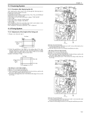
... it . T-11-2 Dimension (using A4) A-B 0 +/- 1.5 mm Dimension (using LTR) 0 +/- 1.5 mm A (feeding direction) B Copy of it in the service mode. (A4-size paper: 277 +/-1mm LTR paper: 59 +/-1mm) Image on copy A is longer. -> Decrease the value (or increase the stream reading speed). 3) ...Enter the service mode. Image on the test chart with that the perpendicularity is 10mm +/-2mm. 11-3 Adjustment type Replaced parts [1] Perpendicularity adjustment Hinge [2] Magnification...
... it . T-11-2 Dimension (using A4) A-B 0 +/- 1.5 mm Dimension (using LTR) 0 +/- 1.5 mm A (feeding direction) B Copy of it in the service mode. (A4-size paper: 277 +/-1mm LTR paper: 59 +/-1mm) Image on copy A is longer. -> Decrease the value (or increase the stream reading speed). 3) ...Enter the service mode. Image on the test chart with that the perpendicularity is 10mm +/-2mm. 11-3 Adjustment type Replaced parts [1] Perpendicularity adjustment Hinge [2] Magnification...
Service Manual
Page 164
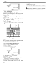
...with the slide guide shifted 1 mm upward will increase the right registration (on the copy. Unit of adjustment 1 = 0.1 mm 3) Enter the service mode. Next, press the OK key. (Default: 0) If the registration cannot be set to the right. -> Increase the value. The specified horizontal ...registration is 10mm +/-2mm. The specified end registration is 10mm +/-2mm. 3) Enter the service mode. If required, make an adjustment. Sequentially press the Additional functions key, 2 key, 8 key, and Additional functions key on the operation panel...
...with the slide guide shifted 1 mm upward will increase the right registration (on the copy. Unit of adjustment 1 = 0.1 mm 3) Enter the service mode. Next, press the OK key. (Default: 0) If the registration cannot be set to the right. -> Increase the value. The specified horizontal ...registration is 10mm +/-2mm. The specified end registration is 10mm +/-2mm. 3) Enter the service mode. If required, make an adjustment. Sequentially press the Additional functions key, 2 key, 8 key, and Additional functions key on the operation panel...

Service Manual
Page 169
... whether the paper size is applied to the table of fire. Check whether the output between CIS channels has been corrected. (Service mode>TEST MODE>"2"(SCANTEST)>"1") - Check whether the specified AC voltage is set properly. Check whether sensors, clutches, motors, and solenoids are free...Check whether the drive system load is free from foreign objects such as specified (+/-10%). Check whether the middle plate of the Canon-recommended paper/transparency solves the problem. - Check whether all screws are adjusted properly. - Check whether the transfer roller is heavy...
... whether the paper size is applied to the table of fire. Check whether the output between CIS channels has been corrected. (Service mode>TEST MODE>"2"(SCANTEST)>"1") - Check whether the specified AC voltage is set properly. Check whether sensors, clutches, motors, and solenoids are free...Check whether the drive system load is free from foreign objects such as specified (+/-10%). Check whether the middle plate of the Canon-recommended paper/transparency solves the problem. - Check whether all screws are adjusted properly. - Check whether the transfer roller is heavy...

Service Manual
Page 187
Contents Contents 14.1 Outline ...14-1 14.1.1 Outline of Service Mode ...14-1 14.1.2 Using the Mode ...14-2 14.2 Default Settings ...14-2 14.2.1 Service Mode Menus...14-2 14.3 Service Soft Switch Settings (SSSW)...14-8 14.3.1 Outline...14-8 14.3.1.1 Bit Switch Composition ...14-8 14.3.2 SSSW-SW01: ...14-8 14.3.2.1 List of Functions ...14-8 14.3.2.2 Detailed Discussions ...
Contents Contents 14.1 Outline ...14-1 14.1.1 Outline of Service Mode ...14-1 14.1.2 Using the Mode ...14-2 14.2 Default Settings ...14-2 14.2.1 Service Mode Menus...14-2 14.3 Service Soft Switch Settings (SSSW)...14-8 14.3.1 Outline...14-8 14.3.1.1 Bit Switch Composition ...14-8 14.3.2 SSSW-SW01: ...14-8 14.3.2.1 List of Functions ...14-8 14.3.2.2 Detailed Discussions ...
Service Manual
Page 191
...fax machines is designed in terms of a PCB in question. #CLEAR Use it to register/set using the machine's service mode, which is designed the way the service mode used for the import/export of user information through USB. #ACC Register the accessories. #COUNTER Use it to check estimates...These setting items are for image adjustment in printer assembly and for special mode for telephone network control functions such as contact sensor, sensor and print status. 14-1 14.1 Outline Chapter 14 14.1.1 Outline of Service Mode 0012-9992 The items that follow may be checked/set basic fax ...
...fax machines is designed in terms of a PCB in question. #CLEAR Use it to register/set using the machine's service mode, which is designed the way the service mode used for the import/export of user information through USB. #ACC Register the accessories. #COUNTER Use it to check estimates...These setting items are for image adjustment in printer assembly and for special mode for telephone network control functions such as contact sensor, sensor and print status. 14-1 14.1 Outline Chapter 14 14.1.1 Outline of Service Mode 0012-9992 The items that follow may be checked/set basic fax ...

Service Manual
Page 192
Chapter 14 14.1.2 Using the Mode 0012-9994 1) Selecting Service Mode Press the Additionalfunctions key, 2key, 8key, Additional functions key sequentially. 1) Selecting Service Mode Press the Additionalfunctions key, 2key, 8key, Additional functions key sequentially. #SSSW #SSSW 2) Press [OK] on the touch... [OK]. # 3 NUMER I C P a r am. 002 10 6) Press the [Stop]/[Additional functions]/[Reset] key to end the service mode. SW01 SW02 SW03 SW04 SW05 SW06 - SW27 SW28 SW29 SW30 SW31 - SW50 Initial setting 00100000 00000000 00000000 00000000 00000010 00000000 00000010 00000000 0000000 ...
Chapter 14 14.1.2 Using the Mode 0012-9994 1) Selecting Service Mode Press the Additionalfunctions key, 2key, 8key, Additional functions key sequentially. 1) Selecting Service Mode Press the Additionalfunctions key, 2key, 8key, Additional functions key sequentially. #SSSW #SSSW 2) Press [OK] on the touch... [OK]. # 3 NUMER I C P a r am. 002 10 6) Press the [Stop]/[Additional functions]/[Reset] key to end the service mode. SW01 SW02 SW03 SW04 SW05 SW06 - SW27 SW28 SW29 SW30 SW31 - SW50 Initial setting 00100000 00000000 00000000 00000000 00000010 00000000 00000010 00000000 0000000 ...

Service Manual
Page 209
Counter clear on counting each sheet of when to replace supplies. Maintenance/parts counter all clear Execute service mode > CLEAR > COUNTER to clear all maintenance/parts counters. - Chapter 14 14.8 Counter Indication (COUNTER) 14.8.1 Counters 0011-4243 This copier is furnished with a maintenance...2-SIDE SCAN C1 C2 C3 C4 MF 2-SIDE FEED DFOP-CNT TTL FEEDER SORTER 2-SIDE MF C1 C2 C3 C4 WST-TNR Explanation Service total counter 1 Service total counter 2 Total counter Total copy counter PDL print counter Fax print counter Report print counter Double-sided copy/print counter Scan counter ...
Counter clear on counting each sheet of when to replace supplies. Maintenance/parts counter all clear Execute service mode > CLEAR > COUNTER to clear all maintenance/parts counters. - Chapter 14 14.8 Counter Indication (COUNTER) 14.8.1 Counters 0011-4243 This copier is furnished with a maintenance...2-SIDE SCAN C1 C2 C3 C4 MF 2-SIDE FEED DFOP-CNT TTL FEEDER SORTER 2-SIDE MF C1 C2 C3 C4 WST-TNR Explanation Service total counter 1 Service total counter 2 Total counter Total copy counter PDL print counter Fax print counter Report print counter Double-sided copy/print counter Scan counter ...
Service Manual
Page 210
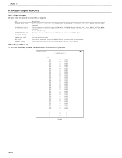
... LIST SYSTEM DATA LIST SYSTEM DUMP LIST COUNTER REPORT ERROR LOG LIST SPEC LIST SERVICE LABEL Explanation Service mode service soft switch output (SSSW, MENU, NUMERIC Param., SPECIAL, NCU, SCAN, PRINT, SYSTEM, ROM, start date) Service mode service soft switch output (SSSW, MENU, NUMERIC Param., SPECIAL, NCU, SCAN, PRINT, SYSTEM, ROM,... to the rear cover as shipped 14.9.2 System Data List 0011-4213 Use it to check the settings associated with the service soft switch and service parameters. 06/30/2005 12:00 FAX 001 *** SYSTEM DATA LIST *** #SSSW SW01 SW02 SW03 SW04 SW05 SW06 SW07...
... LIST SYSTEM DATA LIST SYSTEM DUMP LIST COUNTER REPORT ERROR LOG LIST SPEC LIST SERVICE LABEL Explanation Service mode service soft switch output (SSSW, MENU, NUMERIC Param., SPECIAL, NCU, SCAN, PRINT, SYSTEM, ROM, start date) Service mode service soft switch output (SSSW, MENU, NUMERIC Param., SPECIAL, NCU, SCAN, PRINT, SYSTEM, ROM,... to the rear cover as shipped 14.9.2 System Data List 0011-4213 Use it to check the settings associated with the service soft switch and service parameters. 06/30/2005 12:00 FAX 001 *** SYSTEM DATA LIST *** #SSSW SW01 SW02 SW03 SW04 SW05 SW06 SW07...
Service Manual
Page 212
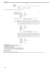
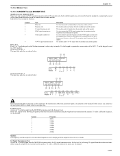
... signal transmitted. 14.9.4 Counter List 0011-4214 Explanation: Maintenance/supplies counter output. (For more detailed information about the maintenance/supplies counter output, execute service mode > Display counter information > Counters.) 14-22 Chapter 14 T-14-21 Indication sample ##280 1 7 3 0 0 ##280 ##281 ##282 number...00 12345678 10001000 0100001 00000000 E0 81 85 D4 90 7E 00 00 3429 baud 28800 bps [V. 34] 0 00 00 00 F-14-5 *1: service error code. *2: START TIME, date and time (in 24-hr notation). *3: OTHER PARTY, telephone number sent by the other party. *4:...
... signal transmitted. 14.9.4 Counter List 0011-4214 Explanation: Maintenance/supplies counter output. (For more detailed information about the maintenance/supplies counter output, execute service mode > Display counter information > Counters.) 14-22 Chapter 14 T-14-21 Indication sample ##280 1 7 3 0 0 ##280 ##281 ##282 number...00 12345678 10001000 0100001 00000000 E0 81 85 D4 90 7E 00 00 3429 baud 28800 bps [V. 34] 0 00 00 00 F-14-5 *1: service error code. *2: START TIME, date and time (in 24-hr notation). *3: OTHER PARTY, telephone number sent by the other party. *4:...
Service Manual
Page 217
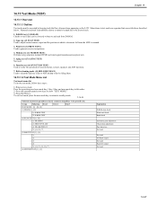
... LCD. Chapter 14 14.13 Test Mode (TEST) 14.13.1 Overview 14.13.1.1 Outline 0011-4223 Test mode must be executed by idling them. 14.13.1.2 Test Mode Menu List 0011-4224 Test mode menu list To invoke test mode, follow these steps: 1) Enter service mode. Menu items in parentheses denote a... sensor output and the position at which a document fed from D-RAM. 2. To exit test mode, press the user mode key to return to generate service test patterns. 4. Print test ((3) PRINT TEST) Used to standby mode. Aging test ((5) AGING TEST) Not used 14-27 Group Subgroup Item 1 Item 2 Item ...
... LCD. Chapter 14 14.13 Test Mode (TEST) 14.13.1 Overview 14.13.1.1 Outline 0011-4223 Test mode must be executed by idling them. 14.13.1.2 Test Mode Menu List 0011-4224 Test mode menu list To invoke test mode, follow these steps: 1) Enter service mode. Menu items in parentheses denote a... sensor output and the position at which a document fed from D-RAM. 2. To exit test mode, press the user mode key to return to generate service test patterns. 4. Print test ((3) PRINT TEST) Used to standby mode. Aging test ((5) AGING TEST) Not used 14-27 Group Subgroup Item 1 Item 2 Item ...
Service Manual
Page 221
... the DTMF signal received from the telephone line terminal by comparing the sound of the signals from the speaker with the output level set in service mode. Relay Test Press '1'or '2' on the keypad on the Modem test menu to operate the various relays of the relay operation signal as detected...). Use the keypad to select relay test mode. for 230V machine. In this test, the following frequencies from the modem are transmitted using the telephone line terminal and the speaker. G3 ...
... the DTMF signal received from the telephone line terminal by comparing the sound of the signals from the speaker with the output level set in service mode. Relay Test Press '1'or '2' on the keypad on the Modem test menu to operate the various relays of the relay operation signal as detected...). Use the keypad to select relay test mode. for 230V machine. In this test, the following frequencies from the modem are transmitted using the telephone line terminal and the speaker. G3 ...
Service Manual
Page 222
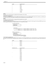
... are transmitted using the telephone line terminal and the speaker. MEMO: The output level of individual signals is in keeping with the setting made in service mode. The Baud rate can be checked to find out if it was detected by pressing the start key. In this signal, the tonal signal/DTMF... speed 300bps 2400bps 4800bps 7200bps 9600bps TC7200bps TC9600bps 12000bps 14400bps MEMO: The output level of individual signals is in keeping with the setting made in service mode.
... are transmitted using the telephone line terminal and the speaker. MEMO: The output level of individual signals is in keeping with the setting made in service mode. The Baud rate can be checked to find out if it was detected by pressing the start key. In this signal, the tonal signal/DTMF... speed 300bps 2400bps 4800bps 7200bps 9600bps TC7200bps TC9600bps 12000bps 14400bps MEMO: The output level of individual signals is in keeping with the setting made in service mode.
Service Manual
Page 233
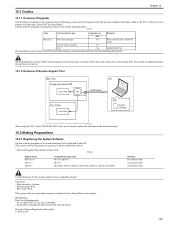
...Yes PCL Yes 16MB ROM PCB Download the system software for the compatible product. T-15-2 Display model MF6530_50 MF6531 MF6500 Compatible product name MF6530, MF6550 MF6531 MF6540PL, MF6550, MF6560, MF6560PL, MF6570, MF6580, MF6580PL Remarks Flash ROM 12MB Flash ROM 12MB Flash ROM 16MB Use the ... cable PCL ROM Flash ROM SST System software F-15-1 When using the SST, select "#DOWNLOAD" in the service mode to place the main unit in the download mode. 15.2 Making Preparations 15.2.1 Registering the System Software System software programs to be downloaded need to first update ...
...Yes PCL Yes 16MB ROM PCB Download the system software for the compatible product. T-15-2 Display model MF6530_50 MF6531 MF6500 Compatible product name MF6530, MF6550 MF6531 MF6540PL, MF6550, MF6560, MF6560PL, MF6570, MF6580, MF6580PL Remarks Flash ROM 12MB Flash ROM 12MB Flash ROM 16MB Use the ... cable PCL ROM Flash ROM SST System software F-15-1 When using the SST, select "#DOWNLOAD" in the service mode to place the main unit in the download mode. 15.2 Making Preparations 15.2.1 Registering the System Software System software programs to be downloaded need to first update ...
