

Hardware Installation Guide
Page 128
... twisted-pair crossover cable schematics. Figure B-7 shows the four twisted-pair crossover cable schematics. Figure B-2 10/100 Port Pinouts Pin Label 1 RD+ 2 RD- 3 TD+ 4 NC 5 NC 6 TD- 7 NC 8 NC 12345678 H5318 Catalyst 3750 Switch Hardware Installation Guide B-4 78-15136-02 Figure B-7 shows the four twisted-pair straight-through cable to connect two ports only...
... twisted-pair crossover cable schematics. Figure B-7 shows the four twisted-pair crossover cable schematics. Figure B-2 10/100 Port Pinouts Pin Label 1 RD+ 2 RD- 3 TD+ 4 NC 5 NC 6 TD- 7 NC 8 NC 12345678 H5318 Catalyst 3750 Switch Hardware Installation Guide B-4 78-15136-02 Figure B-7 shows the four twisted-pair straight-through cable to connect two ports only...
Hardware Installation Guide
Page 131
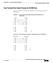
... for 10/100 Ports MT 10/100 1 RD+ 2 RD3 TD+ 6 TD- Switch 1 TD+ 2 TD3 RD+ 6 RD- 4 NC 5 NC 7 NC 8 NC 4 NC 5 NC 7 NC 8 NC 65271 Figure B-8 Four Twisted-Pair Crossover Cable Schematic for 10/100 ports. Switch/Hub 1 RD+ 2 RD3 TD+ 6 TD- 4 NC 5 NC 7 NC 8 NC 4 NC 5 NC 7 NC 8 NC 65273 78-15136-02 Catalyst 3750 Switch Hardware Installation Guide B-7 Figure B-7 Four Twisted-Pair Straight-Through...
... for 10/100 Ports MT 10/100 1 RD+ 2 RD3 TD+ 6 TD- Switch 1 TD+ 2 TD3 RD+ 6 RD- 4 NC 5 NC 7 NC 8 NC 4 NC 5 NC 7 NC 8 NC 65271 Figure B-8 Four Twisted-Pair Crossover Cable Schematic for 10/100 ports. Switch/Hub 1 RD+ 2 RD3 TD+ 6 TD- 4 NC 5 NC 7 NC 8 NC 4 NC 5 NC 7 NC 8 NC 65273 78-15136-02 Catalyst 3750 Switch Hardware Installation Guide B-7 Figure B-7 Four Twisted-Pair Straight-Through...