Quick Start Guide
Page 12
... to all national laws and regulations. Installing the Router Note Cisco 2800 series routers are not designed to support the weight of this product should be allowed to install, replace, or service this equipment to a general-purpose outlet could be... hazardous. Always hold the chassis by the plastic panel on the front. Statement 1032 Warning This equipment must be provided as power supplies, fans...
... to all national laws and regulations. Installing the Router Note Cisco 2800 series routers are not designed to support the weight of this product should be allowed to install, replace, or service this equipment to a general-purpose outlet could be... hazardous. Always hold the chassis by the plastic panel on the front. Statement 1032 Warning This equipment must be provided as power supplies, fans...
Quick Start Guide
Page 29
...Cisco Router and Security Device Manager (SDM)" section on page 32 to learn how to configure your router...Cisco Router and Security Device Manager (SDM): yourname con0 is installed on your router. • If you see the following URL: http://www.cisco...the router, see the "Initial ...router to abort configuration dialog at the following messages, the router...Cisco 2800 series software configuration documentation at the following messages, the router has booted and is ready to configure the router, see the "Initial Configuration Using the Cisco... in the online Cisco 2800 series hardware ...
...Cisco Router and Security Device Manager (SDM)" section on page 32 to learn how to configure your router...Cisco Router and Security Device Manager (SDM): yourname con0 is installed on your router. • If you see the following URL: http://www.cisco...the router, see the "Initial ...router to abort configuration dialog at the following messages, the router...Cisco 2800 series software configuration documentation at the following messages, the router has booted and is ready to configure the router, see the "Initial Configuration Using the Cisco... in the online Cisco 2800 series hardware ...
User Guide
Page 17
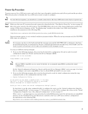
... page 13. Contact the appropriate electrical inspection authority or an electrician if you are located internally within a Cisco 2811 series integrated services router. Installing and Upgrading Fans in Cisco 2811 Series Routers This document describes how to install or upgrade fans that are uncertain that has an on/off switch, turn OFF the power and unplug the power...
... page 13. Contact the appropriate electrical inspection authority or an electrician if you are located internally within a Cisco 2811 series integrated services router. Installing and Upgrading Fans in Cisco 2811 Series Routers This document describes how to install or upgrade fans that are uncertain that has an on/off switch, turn OFF the power and unplug the power...

User Guide
Page 18
... screwdriver and a flat-blade screwdriver with or attempt to remove the safety shields protecting the WIC/HWIC slots and connectors on the Cisco 2811 routers. The following procedures, ensure that power is provided with a DC power input: Warning Before performing any circumstances, tamper with a ...it free from the unit first. Rack-mounted routers must be removed from Cisco 2811 Routers To remove the chassis cover for a Cisco 2811 series router, follow this procedure to remove the cover. Statement 1003 Installing and Upgrading Fans in WAN ports regardless of the chassis on the...
... screwdriver and a flat-blade screwdriver with or attempt to remove the safety shields protecting the WIC/HWIC slots and connectors on the Cisco 2811 routers. The following procedures, ensure that power is provided with a DC power input: Warning Before performing any circumstances, tamper with a ...it free from the unit first. Rack-mounted routers must be removed from Cisco 2811 Routers To remove the chassis cover for a Cisco 2811 series router, follow this procedure to remove the cover. Statement 1003 Installing and Upgrading Fans in WAN ports regardless of the chassis on the...
User Guide
Page 19
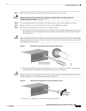
...past the chassis and into the narrow slot. With the screwdriver positioned as required in Cisco 2811 Series Routers 3 Perform the following steps to avoid contact with moderate effort, make sure that the router is turned off and disconnected from the chassis: a. See Figure 1. Caution Make sure...may be fairly tight; Repeat Step a. for the opposite side of the Chassis Screwdriver must not enter the vertical slot b. Installing and Upgrading Fans in Step a. Statement 1041 Step 2 Step 3 Step 4 If rack-mounting brackets are attached to Loosen the Chassis Cover 103861 103860 78-...
...past the chassis and into the narrow slot. With the screwdriver positioned as required in Cisco 2811 Series Routers 3 Perform the following steps to avoid contact with moderate effort, make sure that the router is turned off and disconnected from the chassis: a. See Figure 1. Caution Make sure...may be fairly tight; Repeat Step a. for the opposite side of the Chassis Screwdriver must not enter the vertical slot b. Installing and Upgrading Fans in Step a. Statement 1041 Step 2 Step 3 Step 4 If rack-mounting brackets are attached to Loosen the Chassis Cover 103861 103860 78-...

User Guide
Page 20
However, do not use the screwdriver again as in Step 4, there may still be free. Figure 3 Cisco 2811 Router-Cover in Cisco 2811 Series Routers 4 78-17850-01 for Removal Plastic bezel Approx. 1 inch (25 mm) 103477 Installing and Upgrading Fans in Position for one or both sides of the cover should now be positioned back... some friction to 7 mm). If it contacts a stop (about 1/4 inch (6 to overcome as you complete the removal. Slide the cover toward the back of the router chassis.
However, do not use the screwdriver again as in Step 4, there may still be free. Figure 3 Cisco 2811 Router-Cover in Cisco 2811 Series Routers 4 78-17850-01 for Removal Plastic bezel Approx. 1 inch (25 mm) 103477 Installing and Upgrading Fans in Position for one or both sides of the cover should now be positioned back... some friction to 7 mm). If it contacts a stop (about 1/4 inch (6 to overcome as you complete the removal. Slide the cover toward the back of the router chassis.
User Guide
Page 21
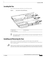
... the wrist strap to IOS show proper air flow. Figure 4 Fan Locations in Cisco 2811 Routers 3 2 1 271118 1 System fan 3 Power supply fan 2 System fan Note The fan numbers in Figure 4 correllate to the metal part of the fans in a Cisco 2811 series router. Caution When you remove or install a fan, remove the chassis cover as described in the "Removing the Chassis...
... the wrist strap to IOS show proper air flow. Figure 4 Fan Locations in Cisco 2811 Routers 3 2 1 271118 1 System fan 3 Power supply fan 2 System fan Note The fan numbers in Figure 4 correllate to the metal part of the fans in a Cisco 2811 series router. Caution When you remove or install a fan, remove the chassis cover as described in the "Removing the Chassis...
User Guide
Page 22
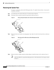
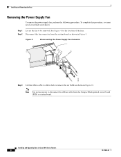
... 8. Step 2 Disconnect the fan connector from the system board as shown in Figure 6. See Figure 4 for leverage as shown in Cisco 2811 Series Routers 6 78-17850-01 Installing and Removing the Fans Removing the System Fans To remove a system fan, perform the following procedure. ...Figure 5 Disconnecting the System Fan Connector from the System Board 170494 Step 3 Remove the fan wire from the Wire ...
... 8. Step 2 Disconnect the fan connector from the system board as shown in Figure 6. See Figure 4 for leverage as shown in Cisco 2811 Series Routers 6 78-17850-01 Installing and Removing the Fans Removing the System Fans To remove a system fan, perform the following procedure. ...Figure 5 Disconnecting the System Fan Connector from the System Board 170494 Step 3 Remove the fan wire from the Wire ...
User Guide
Page 23
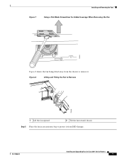
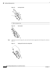
Figure 8 Lifting and Tilting the Fan to Remove 21 170498 1 Lift the fan upward 2 Tilt the fan toward chassis Step 5 Place the fan in an antistatic bag to remove it from the chassis to protect it . Installing and Removing the Fans Figure 7 Using a Flat-Blade Screwdriver for Added Leverage When Removing the Fan 170531 Figure 8 shows the fan being tilted away from ESD damage. 78-17850-01 Installing and Upgrading Fans in Cisco 2811 Series Routers 7
Figure 8 Lifting and Tilting the Fan to Remove 21 170498 1 Lift the fan upward 2 Tilt the fan toward chassis Step 5 Place the fan in an antistatic bag to remove it from the chassis to protect it . Installing and Removing the Fans Figure 7 Using a Flat-Blade Screwdriver for Added Leverage When Removing the Fan 170531 Figure 8 shows the fan being tilted away from ESD damage. 78-17850-01 Installing and Upgrading Fans in Cisco 2811 Series Routers 7
User Guide
Page 24
... Figure 10. Step 2 Disconnect the fan connector from the CompactFlash printed circuit board (PCB) or system board. Step 1 Locate the fan to remove the air baffle as shown in Figure 9. Note It is not necessary to disconnect the ribbon cable from the system board as shown in Cisco 2811 Series Routers 8 78-17850-01
... Figure 10. Step 2 Disconnect the fan connector from the CompactFlash printed circuit board (PCB) or system board. Step 1 Locate the fan to remove the air baffle as shown in Figure 9. Note It is not necessary to disconnect the ribbon cable from the system board as shown in Cisco 2811 Series Routers 8 78-17850-01

User Guide
Page 25
...Step 4 Remove the plastic air baffle by placing a flat-blade screwdriver at the base of the plastic fan housing and lifting the fan in a vertical position, as shown in Figure 6. Remove the fan by gently squeezing the air baffle sides, disengaging the baffle from the wire management clip, which is ...located on the chassis base as shown in Figure 12. 78-17850-01 Installing and Upgrading Fans in Figure 11. Figure 11 Removing the Air Baffle 170512 Step 5 Step 6 Remove the fan wire from the chassis base as shown in Cisco 2811 Series Routers 9
...Step 4 Remove the plastic air baffle by placing a flat-blade screwdriver at the base of the plastic fan housing and lifting the fan in a vertical position, as shown in Figure 6. Remove the fan by gently squeezing the air baffle sides, disengaging the baffle from the wire management clip, which is ...located on the chassis base as shown in Figure 12. 78-17850-01 Installing and Upgrading Fans in Figure 11. Figure 11 Removing the Air Baffle 170512 Step 5 Step 6 Remove the fan wire from the chassis base as shown in Cisco 2811 Series Routers 9

User Guide
Page 26
Figure 13 Disengaging the Fan from the Side Attachment Slots 170530 Step 8 Place the fan in an antistatic bag to Lift the Fan 170513 Step 7 Disengage the fan from ESD damage. Installing and Upgrading Fans in Cisco 2811 Series Routers 10 78-17850-01 Installing and Removing the Fans Figure 12 Using a Flat-Blade Screwdriver to protect it from the side attachment slots and push the fan toward the center of the chassis, and remove the fan as shown in Figure 13.
Figure 13 Disengaging the Fan from the Side Attachment Slots 170530 Step 8 Place the fan in an antistatic bag to Lift the Fan 170513 Step 7 Disengage the fan from ESD damage. Installing and Upgrading Fans in Cisco 2811 Series Routers 10 78-17850-01 Installing and Removing the Fans Figure 12 Using a Flat-Blade Screwdriver to protect it from the side attachment slots and push the fan toward the center of the chassis, and remove the fan as shown in Figure 13.
User Guide
Page 27
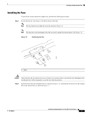
...Installing and Upgrading Fans in position. Note The fans have side attachment slots that the side attachment slots are used to guide the fan into place. Misaligned side attachment slots will not properly secure the fan when in Cisco 2811 Series Routers 11 See Figure 16. Note The fan should seat ...within the four tabs shown in Figure 14. Figure 14 Positioning the Fan 170515 1 1 Tabs Caution ...
...Installing and Upgrading Fans in position. Note The fans have side attachment slots that the side attachment slots are used to guide the fan into place. Misaligned side attachment slots will not properly secure the fan when in Cisco 2811 Series Routers 11 See Figure 16. Note The fan should seat ...within the four tabs shown in Figure 14. Figure 14 Positioning the Fan 170515 1 1 Tabs Caution ...
User Guide
Page 28
Installing and Removing the Fans Figure 15 Inserting the Fan 1 1 170518 1 Side attachment slots Figure 16 Fan Inserted 170522 Step 3 Angle the fan into the locking tabs, and verify that the fan has snapped into the locking tabs as shown in Cisco 2811 Series Routers 12 78-17850-01 Figure 17 Angling the Fan Into the Locking Tabs 170519 Installing and Upgrading Fans in Figure 17.
Installing and Removing the Fans Figure 15 Inserting the Fan 1 1 170518 1 Side attachment slots Figure 16 Fan Inserted 170522 Step 3 Angle the fan into the locking tabs, and verify that the fan has snapped into the locking tabs as shown in Cisco 2811 Series Routers 12 78-17850-01 Figure 17 Angling the Fan Into the Locking Tabs 170519 Installing and Upgrading Fans in Figure 17.
User Guide
Page 29
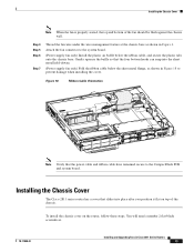
...number 2 flat-blade screwdriver. 78-17850-01 Installing and Upgrading Fans in Figure 6. Installing the Chassis Cover Note When the fan is properly seated, the top and bottom of the chassis. Installing the Chassis Cover The Cisco 2811 series router has a cover that the power cable and ribbon cable have... remained secure to the system board. (Power supply fan only) Install the plastic air...
...number 2 flat-blade screwdriver. 78-17850-01 Installing and Upgrading Fans in Figure 6. Installing the Chassis Cover Note When the fan is properly seated, the top and bottom of the chassis. Installing the Chassis Cover The Cisco 2811 series router has a cover that the power cable and ribbon cable have... remained secure to the system board. (Power supply fan only) Install the plastic air...

User Guide
Page 30
...of the chassis. Installing the Chassis Cover Step 1 Position the cover so that the male flanges enter the slots and the cover is a service mark of Cisco Systems, Inc.; Changing the Way We Work, Live, Play, and Learn is fully closed . and Access Registrar, Aironet, Catalyst, CCDA,...or Website are trademarks of the cover. and/or its affiliates in Cisco 2811 Series Routers 14 78-17850-01 Installing and Upgrading Fans in the United States and certain other company. (0711R) Copyright © 2006 Cisco Systems, Inc. Use a Phillips screwdriver to install the four screws ...
...of the chassis. Installing the Chassis Cover Step 1 Position the cover so that the male flanges enter the slots and the cover is a service mark of Cisco Systems, Inc.; Changing the Way We Work, Live, Play, and Learn is fully closed . and Access Registrar, Aironet, Catalyst, CCDA,...or Website are trademarks of the cover. and/or its affiliates in Cisco 2811 Series Routers 14 78-17850-01 Installing and Upgrading Fans in the United States and certain other company. (0711R) Copyright © 2006 Cisco Systems, Inc. Use a Phillips screwdriver to install the four screws ...
User Guide
Page 40
... ambient temperatures above 40oC. The Cisco 2801 router with inline power includes two additional fans integrated with time of four fans. Caution Ensure the device is not intended to excessive pre-heating of inspection and cleaning is not field-replaceable. Cleaning involves vacuuming of dust or debris may require fan servicing. The Cisco 2801 router has a socketed lithium battery...
... ambient temperatures above 40oC. The Cisco 2801 router with inline power includes two additional fans integrated with time of four fans. Caution Ensure the device is not intended to excessive pre-heating of inspection and cleaning is not field-replaceable. Cleaning involves vacuuming of dust or debris may require fan servicing. The Cisco 2801 router has a socketed lithium battery...

User Guide
Page 61
... discharge can be found by itself, if possible. Ensure that the chassis cover and module rear panels are not available for Cisco 2801 routers. Heat generated by equipment near the bottom of the rack can cause immediate or intermittent equipment failure. • Ensure that ... louvered sides and a fan to draw cooling air through specially designed cooling slots. A chassis with a 19-inch rack or, if specified in an enclosed rack) fails, try operating the equipment by experimenting with a 23-inch rack. Equipment Racks Cisco 2800 series routers include brackets for use ...
... discharge can be found by itself, if possible. Ensure that the chassis cover and module rear panels are not available for Cisco 2801 routers. Heat generated by equipment near the bottom of the rack can cause immediate or intermittent equipment failure. • Ensure that ... louvered sides and a fan to draw cooling air through specially designed cooling slots. A chassis with a 19-inch rack or, if specified in an enclosed rack) fails, try operating the equipment by experimenting with a 23-inch rack. Equipment Racks Cisco 2800 series routers include brackets for use ...

User Guide
Page 81
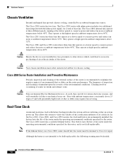
...rack-mount bracket using the screw provided, as power supplies, fans, or cards); OL-5786-03 Chassis Installation Procedures for organizing and routing cables. Setting Up the Chassis Warning To prevent bodily injury when mounting or servicing this unit in a partially filled rack, load the rack ...from the bottom to the left or right rack-mount brackets using the screw provided. On brackets for 2-rack-unit-high Cisco 2821 and Cisco 2851 routers, you must take special precautions to...
...rack-mount bracket using the screw provided, as power supplies, fans, or cards); OL-5786-03 Chassis Installation Procedures for organizing and routing cables. Setting Up the Chassis Warning To prevent bodily injury when mounting or servicing this unit in a partially filled rack, load the rack ...from the bottom to the left or right rack-mount brackets using the screw provided. On brackets for 2-rack-unit-high Cisco 2821 and Cisco 2851 routers, you must take special precautions to...
User Guide
Page 82
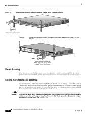
... a desktop, you must first install the four rubber feet that are not designed to a Cisco 2811, 2821, or 2851 Router ENM0 S L O T 3 S L O T S L O 1 T 2 A F A= ACT S= SPEED FE 0/1 A= FDX A= LINK FE 0/0 A S L S F OL T S 0 L PVDM1 PVDM0 AIM1 AIM0 95947 Cable management bracket. Warning To...kit. Peel the rubber feet from the adhesive strip, and stick them onto the features marked "+" on modules (such as power supplies, fans, or cards); For the chassis ground connection procedures, see the "Installing the Chassis Ground Connection" section on a desktop or shelf. ...
... a desktop, you must first install the four rubber feet that are not designed to a Cisco 2811, 2821, or 2851 Router ENM0 S L O T 3 S L O T S L O 1 T 2 A F A= ACT S= SPEED FE 0/1 A= FDX A= LINK FE 0/0 A S L S F OL T S 0 L PVDM1 PVDM0 AIM1 AIM0 95947 Cable management bracket. Warning To...kit. Peel the rubber feet from the adhesive strip, and stick them onto the features marked "+" on modules (such as power supplies, fans, or cards); For the chassis ground connection procedures, see the "Installing the Chassis Ground Connection" section on a desktop or shelf. ...

