Hardware Installation Guide
Page 6
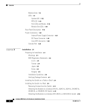
... Connector 1-21 Cisco RPS Connector 1-22 Console Port 1-23 2 C H A P T E R Installation 2-1 Preparing for Installation 2-1 Warnings 2-1 EMC Regulatory Statements 2-4 U.S.A. 2-4 Taiwan 2-4 Japan 2-5 Korea 2-5 Hungary 2-6 Installation Guidelines 2-6 Verifying Package Contents 2-7 Installing the Switch on a Table or Shelf 2-9 Installing the Switch in a Rack 2-9 Removing Screws from the Switch 2-11 Attaching the Brackets to a Catalyst 2912 XL, 2924C XL, 2924 XL, 2912MF XL, 2924M XL, or 2924M XL DC Switch 2-11 Attaching...
... Connector 1-21 Cisco RPS Connector 1-22 Console Port 1-23 2 C H A P T E R Installation 2-1 Preparing for Installation 2-1 Warnings 2-1 EMC Regulatory Statements 2-4 U.S.A. 2-4 Taiwan 2-4 Japan 2-5 Korea 2-5 Hungary 2-6 Installation Guidelines 2-6 Verifying Package Contents 2-7 Installing the Switch on a Table or Shelf 2-9 Installing the Switch in a Rack 2-9 Removing Screws from the Switch 2-11 Attaching the Brackets to a Catalyst 2912 XL, 2924C XL, 2924 XL, 2912MF XL, 2924M XL, or 2924M XL DC Switch 2-11 Attaching...

Hardware Installation Guide
Page 30
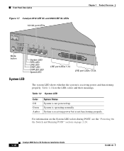
... Catalyst 2900 Series XL and Catalyst 3500 Series XL Software Configuration Guide describes how to use CMS to manage standalone or individual switches and how to use cluster management software to manage switch clusters]. Figure 1-5 Catalyst 2912 XL, 2924 XL, and 2924C XL LEDs 10/100 port LEDs System LED Port mode LEDs MODE 1X 2X 3X 4X 5X 6X 7X Mode RPS button LED 47288 1-10 Catalyst...
... Catalyst 2900 Series XL and Catalyst 3500 Series XL Software Configuration Guide describes how to use CMS to manage standalone or individual switches and how to use cluster management software to manage switch clusters]. Figure 1-5 Catalyst 2912 XL, 2924 XL, and 2924C XL LEDs 10/100 port LEDs System LED Port mode LEDs MODE 1X 2X 3X 4X 5X 6X 7X Mode RPS button LED 47288 1-10 Catalyst...
Hardware Installation Guide
Page 32
... the Switch and Running POST" section on page 2-24. 1-12 Catalyst 2900 Series XL Hardware Installation Guide 78-6461-04 Front-Panel Description Figure 1-7 Catalyst 2912 LRE XL and 2924 LRE XL LEDs 10/100 port LEDs Chapter 1 Product Overview SYSTEM RPS MODE LRE STAT DUPLX SPEED Mode button 1X 2X 3X 4X System LED RPS LED LRE LED STAT LED DUPLEX LED Speed LED LRE port LEDs...
... the Switch and Running POST" section on page 2-24. 1-12 Catalyst 2900 Series XL Hardware Installation Guide 78-6461-04 Front-Panel Description Figure 1-7 Catalyst 2912 LRE XL and 2924 LRE XL LEDs 10/100 port LEDs Chapter 1 Product Overview SYSTEM RPS MODE LRE STAT DUPLX SPEED Mode button 1X 2X 3X 4X System LED RPS LED LRE LED STAT LED DUPLEX LED Speed LED LRE port LEDs...
Hardware Installation Guide
Page 33
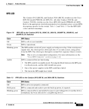
... is operational. Table 1-3 RPS LED on the Catalyst 2912 XL, 2924C XL, 2924 XL, 2924MF XL, 2924M XL, and 2924M XL DC Switches Color Off Green Blinking green Amber RPS Status RPS is connected and ready to the appropriate switch documentation for redundant power system (RPS) descriptions specific for the switch. Chapter 1 Product Overview Front-Panel Description RPS LED The Catalyst 2912 LRE XL and Catalyst 2924 LRE XL switches use the Cisco RPS 600 (model PWR600-AC...
... is operational. Table 1-3 RPS LED on the Catalyst 2912 XL, 2924C XL, 2924 XL, 2924MF XL, 2924M XL, and 2924M XL DC Switches Color Off Green Blinking green Amber RPS Status RPS is connected and ready to the appropriate switch documentation for redundant power system (RPS) descriptions specific for the switch. Chapter 1 Product Overview Front-Panel Description RPS LED The Catalyst 2912 LRE XL and Catalyst 2924 LRE XL switches use the Cisco RPS 600 (model PWR600-AC...

Hardware Installation Guide
Page 34
Press the Standby/Active button on the Catalyst 2912 XL, 2924C XL, 2924 XL, 2924MF XL, 2924M XL, and 2924M XL DC Switches Mode LED STAT UTL FDUP 100 Port Mode Port status Switch utilization Port duplex mode Port speed Description The port status. These port LEDs, as a group or individually, display information about the switch and about the individual ports. When you change a mode, press...
Press the Standby/Active button on the Catalyst 2912 XL, 2924C XL, 2924 XL, 2924MF XL, 2924M XL, and 2924M XL DC Switches Mode LED STAT UTL FDUP 100 Port Mode Port status Switch utilization Port duplex mode Port speed Description The port status. These port LEDs, as a group or individually, display information about the switch and about the individual ports. When you change a mode, press...
Hardware Installation Guide
Page 38
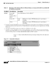
...status user EXEC command. The Catalyst 2900 LRE XL switches do not support the Cisco 585 LRE CPE devices. 2. Figure 1-9 shows bandwidth utilization percentages displayed by the right-most LEDs. Figure 1-9 Bandwidth Utilization 47293 SYSTEM 10BaseT/100BaseTx RPS 1x 2x 3x 4x 5x 6x... Description Chapter 1 Product Overview Table 1-7 Meanings of Port Status LEDs for Different Modes on Catalyst 2912 LRE XL and 2924 LRE XL Switches (continued) Port Mode SPEED Port LED Color Cisco IOS Release 12.0(5.x)WC1/ WC21 Description Cisco IOS Release 12.0(5.x)WC42 3 Cyan (off) Cyan (off) LRE...
...status user EXEC command. The Catalyst 2900 LRE XL switches do not support the Cisco 585 LRE CPE devices. 2. Figure 1-9 shows bandwidth utilization percentages displayed by the right-most LEDs. Figure 1-9 Bandwidth Utilization 47293 SYSTEM 10BaseT/100BaseTx RPS 1x 2x 3x 4x 5x 6x... Description Chapter 1 Product Overview Table 1-7 Meanings of Port Status LEDs for Different Modes on Catalyst 2912 LRE XL and 2924 LRE XL Switches (continued) Port Mode SPEED Port LED Color Cisco IOS Release 12.0(5.x)WC1/ WC21 Description Cisco IOS Release 12.0(5.x)WC42 3 Cyan (off) Cyan (off) LRE...
Hardware Installation Guide
Page 39
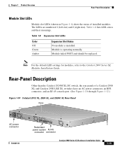
...than the Catalyst 2924M XL DC switch, the rear panels of installed modules. Module is installed. Table 1-8 Expansion Slot LEDs Color Off Green Amber Expansion Slot Status No module is operating normally. Note For the default LED settings for modules, refer to the Catalyst 2900 Series XL Modules ...Slot LEDs Module slot LEDs (shown in Figure 1-6) show the status of a Catalyst 2900 XL and Catalyst 2900 LRE XL switches have an AC power connector, an RPS connector, and an RJ-45 console port. (See Figure 1-10 through Figure 1-12.) Figure 1-10 Catalyst 2912 XL, 2924 XL, and 2924C XL ...
...than the Catalyst 2924M XL DC switch, the rear panels of installed modules. Module is installed. Table 1-8 Expansion Slot LEDs Color Off Green Amber Expansion Slot Status No module is operating normally. Note For the default LED settings for modules, refer to the Catalyst 2900 Series XL Modules ...Slot LEDs Module slot LEDs (shown in Figure 1-6) show the status of a Catalyst 2900 XL and Catalyst 2900 LRE XL switches have an AC power connector, an RPS connector, and an RJ-45 console port. (See Figure 1-10 through Figure 1-12.) Figure 1-10 Catalyst 2912 XL, 2924 XL, and 2924C XL ...


