Hardware Installation Guide
Page 6
... Cisco RPS Connector 1-22 Console Port 1-23 2 C H A P T E R Installation 2-1 Preparing for Installation 2-1 Warnings 2-1 EMC Regulatory Statements 2-4 U.S.A. 2-4 Taiwan 2-4 Japan 2-5 Korea 2-5 Hungary 2-6 Installation Guidelines 2-6 Verifying Package Contents 2-7 Installing the Switch on a Table or Shelf 2-9 Installing the Switch in a Rack 2-9 Removing Screws from the Switch 2-11 Attaching the Brackets to a Catalyst 2912 XL, 2924C XL, 2924 XL, 2912MF XL, 2924M...
... Cisco RPS Connector 1-22 Console Port 1-23 2 C H A P T E R Installation 2-1 Preparing for Installation 2-1 Warnings 2-1 EMC Regulatory Statements 2-4 U.S.A. 2-4 Taiwan 2-4 Japan 2-5 Korea 2-5 Hungary 2-6 Installation Guidelines 2-6 Verifying Package Contents 2-7 Installing the Switch on a Table or Shelf 2-9 Installing the Switch in a Rack 2-9 Removing Screws from the Switch 2-11 Attaching the Brackets to a Catalyst 2912 XL, 2924C XL, 2924 XL, 2912MF XL, 2924M...

Hardware Installation Guide
Page 7
...Switch on a Wall 2-20 Attaching the Brackets to the Switch 2-21 Mounting the Switch to a Wall 2-22 Powering On the Switch and Running POST 2-24 Connecting to DC Power 2-25 Preparing for Installation 2-25 Grounding the Switch... 2-26 Wiring the DC-Input Power Source 2-29 Connecting to a 10/100 Port 2-35 Connecting to a 100BASE-FX Port 2-37 Connecting to an LRE Port 2-38 Connecting to a Module... Port 2-42 Connecting to the Console Port 2-42 Where to Go Next 2-43 Troubleshooting 3-1 Understanding POST Results 3-1 Correcting Module POST Failures 3-2 Diagnosing Problems...
...Switch on a Wall 2-20 Attaching the Brackets to the Switch 2-21 Mounting the Switch to a Wall 2-22 Powering On the Switch and Running POST 2-24 Connecting to DC Power 2-25 Preparing for Installation 2-25 Grounding the Switch... 2-26 Wiring the DC-Input Power Source 2-29 Connecting to a 10/100 Port 2-35 Connecting to a 100BASE-FX Port 2-37 Connecting to an LRE Port 2-38 Connecting to a Module... Port 2-42 Connecting to the Console Port 2-42 Where to Go Next 2-43 Troubleshooting 3-1 Understanding POST Results 3-1 Correcting Module POST Failures 3-2 Diagnosing Problems...
Hardware Installation Guide
Page 16
... help (available only from the switch CMS software) • Catalyst 2900 Series XL Hardware Installation Guide (order number DOC-786461=) • Catalyst 3500 Series XL Hardware Installation Guide (order number DOC-786456=) • Catalyst 2900 Series XL Modules Installation Guide (order number DOC-CAT2900-IG=) • Catalyst 2900 Series XL ATM Modules Installation and Configuration Guide (order...
... help (available only from the switch CMS software) • Catalyst 2900 Series XL Hardware Installation Guide (order number DOC-786461=) • Catalyst 3500 Series XL Hardware Installation Guide (order number DOC-786456=) • Catalyst 2900 Series XL Modules Installation Guide (order number DOC-CAT2900-IG=) • Catalyst 2900 Series XL ATM Modules Installation and Configuration Guide (order...
Hardware Installation Guide
Page 22
...-T, Gigabit Ethernet, and asynchronous transfer mode (ATM) modules • On the Catalyst 2924M XL DC switch, a direct current (DC) power converter • On the Catalyst 2912 LRE XL and 2924 LRE XL switches, up to 24 LRE ports through one RJ-21 connector and hot swapping capability with the Cisco LRE customer premises equipment (CPE) devices •...
...-T, Gigabit Ethernet, and asynchronous transfer mode (ATM) modules • On the Catalyst 2924M XL DC switch, a direct current (DC) power converter • On the Catalyst 2912 LRE XL and 2924 LRE XL switches, up to 24 LRE ports through one RJ-21 connector and hot swapping capability with the Cisco LRE customer premises equipment (CPE) devices •...

Hardware Installation Guide
Page 24
... the CLI, and SNMP refer to support desktop-switching features. Catalyst 2900 Series XL Hardware Installation Guide 1-4 78-6461-04 You can fully configure and monitor a standalone switch, a specific cluster member, or an entire switch cluster. You can manage the switch from the CLI. and port-level settings. ... directly to monitor and control the switch and switch cluster members. All switches have up to twenty-four 10/100 ports (See Figure 1-2), up to twelve 100BASE-FX ports (See Figure 1-3), two module slots (see Figure 1-3), and up to modify switch- Using CMS, you can also ...
... the CLI, and SNMP refer to support desktop-switching features. Catalyst 2900 Series XL Hardware Installation Guide 1-4 78-6461-04 You can fully configure and monitor a standalone switch, a specific cluster member, or an entire switch cluster. You can manage the switch from the CLI. and port-level settings. ... directly to monitor and control the switch and switch cluster members. All switches have up to twenty-four 10/100 ports (See Figure 1-2), up to twelve 100BASE-FX ports (See Figure 1-3), two module slots (see Figure 1-3), and up to modify switch- Using CMS, you can also ...
Hardware Installation Guide
Page 25
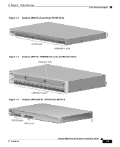
... 22X Catalyst10209B0AS0ES-FEXRIES XL 23 24 10/100 ports 100BASE-FX ports Figure 1-3 Catalyst 2900 XL 100BASE-FX ports and Module Slots Expansion slots 47286 12 1 MODE 2 3 Catalyst 2900 SERIES XL 4 5 100BASE-FX 6 7 8 9 10 11 12 100BASE-FX ports Figure 1-4 Catalyst 2900 LRE XL 10/100 and LRE Ports INPUT OUTPUT PWR PWR RESET...
... 22X Catalyst10209B0AS0ES-FEXRIES XL 23 24 10/100 ports 100BASE-FX ports Figure 1-3 Catalyst 2900 XL 100BASE-FX ports and Module Slots Expansion slots 47286 12 1 MODE 2 3 Catalyst 2900 SERIES XL 4 5 100BASE-FX 6 7 8 9 10 11 12 100BASE-FX ports Figure 1-4 Catalyst 2900 LRE XL 10/100 and LRE Ports INPUT OUTPUT PWR PWR RESET...

Hardware Installation Guide
Page 28
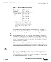
... WS-X2914-XL-V WS-X2922-XL WS-X2922-XL-V WS-X2924-XL-V Catalyst 2900 Series XL Hardware Installation Guide 1-8 78-6461-04 For more information about homologated POTS splitters, contact your Cisco sales representative. Each module port is managed through the switch management interfaces. Digital telephones connected to the patch panel. Note If a connection...
... WS-X2914-XL-V WS-X2922-XL WS-X2922-XL-V WS-X2924-XL-V Catalyst 2900 Series XL Hardware Installation Guide 1-8 78-6461-04 For more information about homologated POTS splitters, contact your Cisco sales representative. Each module port is managed through the switch management interfaces. Digital telephones connected to the patch panel. Note If a connection...
Hardware Installation Guide
Page 29
... restarting that you use the switch LEDs to select a port mode. For a complete list and the minimum software release required, refer to 2048 MAC addresses. If you insert them in a 2924M XL or Catalyst 2912MF XL switch (both supporting 8192 MAC addresses), the module fails POST. LEDs 78-6461...-04 You can start the module by each port LED. Figure 1-5, Figure 1-6, and Figure 1-7 show the location ...
... restarting that you use the switch LEDs to select a port mode. For a complete list and the minimum software release required, refer to 2048 MAC addresses. If you insert them in a 2924M XL or Catalyst 2912MF XL switch (both supporting 8192 MAC addresses), the module fails POST. LEDs 78-6461...-04 You can start the module by each port LED. Figure 1-5, Figure 1-6, and Figure 1-7 show the location ...

Hardware Installation Guide
Page 34
...desired mode is the default mode. Contact Cisco Systems. The internal power supply in a switch has failed, and the RPS is in standby mode or in use by the switch. (See Figure 1-8.) The port duplex ... or 100 Mbps. 1-14 Catalyst 2900 Series XL Hardware Installation Guide 78-6461-04 Port LEDs and Modes Each of the 10/100, 100BASE-FX, and LRE ports and module slots have failed. Table ...Standby/Active button on the Catalyst 2912 XL, 2924C XL, 2924 XL, 2924MF XL, 2924M XL, and 2924M XL DC Switches Mode LED STAT UTL FDUP 100 Port Mode Port status Switch utilization Port duplex mode Port ...
...desired mode is the default mode. Contact Cisco Systems. The internal power supply in a switch has failed, and the RPS is in standby mode or in use by the switch. (See Figure 1-8.) The port duplex ... or 100 Mbps. 1-14 Catalyst 2900 Series XL Hardware Installation Guide 78-6461-04 Port LEDs and Modes Each of the 10/100, 100BASE-FX, and LRE ports and module slots have failed. Table ...Standby/Active button on the Catalyst 2912 XL, 2924C XL, 2924 XL, 2924MF XL, 2924M XL, and 2924M XL DC Switches Mode LED STAT UTL FDUP 100 Port Mode Port status Switch utilization Port duplex mode Port ...
Hardware Installation Guide
Page 39
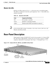
...). Rear-Panel Description Other than the Catalyst 2924M XL DC switch, the rear panels of installed modules. Table 1-8 lists LED colors and their meanings. Module is installed. Chapter 1 Product Overview Rear-Panel Description Module Slot LEDs Module slot LEDs (shown in Figure 1-6) show the status of a Catalyst 2900 XL and Catalyst 2900 LRE XL switches have an AC power connector...
...). Rear-Panel Description Other than the Catalyst 2924M XL DC switch, the rear panels of installed modules. Table 1-8 lists LED colors and their meanings. Module is installed. Chapter 1 Product Overview Rear-Panel Description Module Slot LEDs Module slot LEDs (shown in Figure 1-6) show the status of a Catalyst 2900 XL and Catalyst 2900 LRE XL switches have an AC power connector...
Hardware Installation Guide
Page 42
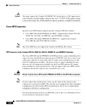
... output power module for four external devices that has an input supply voltage from -36 to -72 VDC. The power source is not in the RPS documentation. The AC input to the Cisco RPS is not. RPS Connector on the Catalyst 2912 XL, 2924C XL, 2924 XL, 2924MF XL, and 2924M XL Switches The Cisco RPS...
... output power module for four external devices that has an input supply voltage from -36 to -72 VDC. The power source is not in the RPS documentation. The AC input to the Cisco RPS is not. RPS Connector on the Catalyst 2912 XL, 2924C XL, 2924 XL, 2924MF XL, and 2924M XL Switches The Cisco RPS...

Hardware Installation Guide
Page 45
.... Installation CH A P T E R 2 This chapter describes how to install your Catalyst 2900 XL switch and interpret the power-on procedures • Connection procedures • Where to go next Note Refer to the Catalyst 2900 Series XL Modules Installation Guide and the Catalyst 2900 Series XL ATM Modules Installation and Configuration Guide for Installation Warnings These warnings are...
.... Installation CH A P T E R 2 This chapter describes how to install your Catalyst 2900 XL switch and interpret the power-on procedures • Connection procedures • Where to go next Note Refer to the Catalyst 2900 Series XL Modules Installation Guide and the Catalyst 2900 Series XL ATM Modules Installation and Configuration Guide for Installation Warnings These warnings are...

Hardware Installation Guide
Page 48
Warning Attach only the Cisco RPS (model PWR600-AC-RPS) to the laser beam. EMC Regulatory Statements U.S.A. Warning Avoid exposure to the RPS receptacle. Under such circumstances, the user may ... A Information product. Avoid exposure and do not stare into open apertures. When used in the front matter of the 100BASE-FX single-mode supervisor engine module. Catalyst 2900 Series XL Hardware Installation Guide 2-4 78-6461-04 Warning Attach only the Cisco RPS (model PWR300-AC-RPS-N1) to the RPS receptacle. Taiwan U.S.
Warning Attach only the Cisco RPS (model PWR600-AC-RPS) to the laser beam. EMC Regulatory Statements U.S.A. Warning Avoid exposure to the RPS receptacle. Under such circumstances, the user may ... A Information product. Avoid exposure and do not stare into open apertures. When used in the front matter of the 100BASE-FX single-mode supervisor engine module. Catalyst 2900 Series XL Hardware Installation Guide 2-4 78-6461-04 Warning Attach only the Cisco RPS (model PWR300-AC-RPS-N1) to the RPS receptacle. Taiwan U.S.

Hardware Installation Guide
Page 51
... the vents is shipped with these conditions: - Your Catalyst 2900 XL switch is unrestricted. • Temperature around it might be easily read. - If any item is within reach of the expansion modules, refer to the modules documentation in the Related Publications, page xv. •... Clearance to front and rear panels meet these items: • Where to Find the Catalyst 2900 XL and Catalyst 3500 XL Documentation flyer • Cisco Documentation CD-ROM •...
... the vents is shipped with these conditions: - Your Catalyst 2900 XL switch is unrestricted. • Temperature around it might be easily read. - If any item is within reach of the expansion modules, refer to the modules documentation in the Related Publications, page xv. •... Clearance to front and rear panels meet these items: • Where to Find the Catalyst 2900 XL and Catalyst 3500 XL Documentation flyer • Cisco Documentation CD-ROM •...
Hardware Installation Guide
Page 81
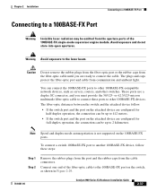
... caps from the cable connectors. The fiber-optic distances between the switch and the attached device follow these ports to the laser beam. Connect one end of the 100BASE-FX single-mode supervisor engine module. Caution Do not remove the rubber plugs from the fiber-optic ... You can connect the 100BASE-FX ports to other 100BASE-FX-compatible network devices, such as shown in Figure 2-29. 78-6461-04 Catalyst 2900 Series XL Hardware Installation Guide 2-37 Chapter 2 Installation Connecting to a 100BASE-FX Port Connecting to a 100BASE-FX Port Warning Invisible laser...
... caps from the cable connectors. The fiber-optic distances between the switch and the attached device follow these ports to the laser beam. Connect one end of the 100BASE-FX single-mode supervisor engine module. Caution Do not remove the rubber plugs from the fiber-optic ... You can connect the 100BASE-FX ports to other 100BASE-FX-compatible network devices, such as shown in Figure 2-29. 78-6461-04 Catalyst 2900 Series XL Hardware Installation Guide 2-37 Chapter 2 Installation Connecting to a 100BASE-FX Port Connecting to a 100BASE-FX Port Warning Invisible laser...
Hardware Installation Guide
Page 86
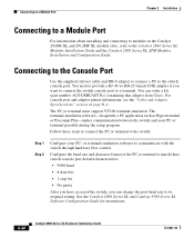
...-emulation software to the Catalyst 2900 Series XL Modules Installation Guide and the Catalyst 2900 Series XL ATM Modules Installation and Configuration Guide. Connecting to a Module Port Chapter 2 Installation Connecting to a Module Port For information about installing and connecting to modules in the Catalyst 2924M XL and 2912MF XL module slots, refer to communicate with the switch through hardware flow control...
...-emulation software to the Catalyst 2900 Series XL Modules Installation Guide and the Catalyst 2900 Series XL ATM Modules Installation and Configuration Guide. Connecting to a Module Port Chapter 2 Installation Connecting to a Module Port For information about installing and connecting to modules in the Catalyst 2924M XL and 2912MF XL module slots, refer to communicate with the switch through hardware flow control...
Hardware Installation Guide
Page 90
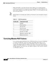
...-XL in a Catalyst 2924M XL or Catalyst 2912MF XL switch, the module fails POST. Catalyst 2900 Series XL Hardware Installation Guide 3-2 78-6461-04 Table 3-1 lists the eight tests and their associated LEDs. This failure occurs because the expansion modules support 2048 MAC addresses and the switch supports 8192 MAC addresses. Call Cisco Systems if your switch does not pass...
...-XL in a Catalyst 2924M XL or Catalyst 2912MF XL switch, the module fails POST. Catalyst 2900 Series XL Hardware Installation Guide 3-2 78-6461-04 Table 3-1 lists the eight tests and their associated LEDs. This failure occurs because the expansion modules support 2048 MAC addresses and the switch supports 8192 MAC addresses. Call Cisco Systems if your switch does not pass...

Hardware Installation Guide
Page 93
...jack and Cisco LRE CPE. Tighten the thumb screws on page B-3. • Replace with or might be attempting to see the "Crossover and Straight-Through Cable Pinouts" section on the module front panel. The following are indicated by the Catalyst 2900 LRE XL switch. Repair ...cable trunking or select an alternative pair. Module not seated in module slot. Telephone cable loose or not connected properly. Chapter 3 ...
...jack and Cisco LRE CPE. Tighten the thumb screws on page B-3. • Replace with or might be attempting to see the "Crossover and Straight-Through Cable Pinouts" section on the module front panel. The following are indicated by the Catalyst 2900 LRE XL switch. Repair ...cable trunking or select an alternative pair. Module not seated in module slot. Telephone cable loose or not connected properly. Chapter 3 ...

Hardware Installation Guide
Page 99
Table A-6 lists the agency approvals for the Catalyst 2900 series switches. A A P P E N D I X Technical Specifications Table A-1, Table A-2, Table A-3, and Table A-5 list the technical specifications for EMI and safety. 78-6461-04 Catalyst 2900 Series XL Hardware Installation Guide A-1 For switches that support modules (Catalyst 2912MF XL and 2924M XL), also refer to the Catalyst 2900 Series XL Modules Installation Guide and the Catalyst 2900 Series XL ATM Modules Installation Guide for additional specifications.
Table A-6 lists the agency approvals for the Catalyst 2900 series switches. A A P P E N D I X Technical Specifications Table A-1, Table A-2, Table A-3, and Table A-5 list the technical specifications for EMI and safety. 78-6461-04 Catalyst 2900 Series XL Hardware Installation Guide A-1 For switches that support modules (Catalyst 2912MF XL and 2924M XL), also refer to the Catalyst 2900 Series XL Modules Installation Guide and the Catalyst 2900 Series XL ATM Modules Installation Guide for additional specifications.
Hardware Installation Guide
Page 100
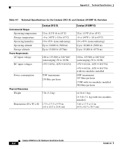
...Technical Specifications Table A-1 Technical Specifications for the Catalyst 2912 XL and Catalyst 2912MF XL Switches Environmental Ranges Operating temperature Storage temperature Operating humidity Operating altitude Storage altitude Power Requirements AC input voltage DC input voltages Catalyst 2912 XL 32 to 113°F (0 to...12V @0.75A with two modules installed 90W (maximum) 307 Btus per hour 170W with two modules installed 580 Btus per hour 14 lb (6.3 kg) 15.5 lb (7.1 kg) with two modules installed 3.46 x 17.5 x 12 in. (8.8 x 44.5 x 30.5 cm) Catalyst 2900 Series XL Hardware Installation...
...Technical Specifications Table A-1 Technical Specifications for the Catalyst 2912 XL and Catalyst 2912MF XL Switches Environmental Ranges Operating temperature Storage temperature Operating humidity Operating altitude Storage altitude Power Requirements AC input voltage DC input voltages Catalyst 2912 XL 32 to 113°F (0 to...12V @0.75A with two modules installed 90W (maximum) 307 Btus per hour 170W with two modules installed 580 Btus per hour 14 lb (6.3 kg) 15.5 lb (7.1 kg) with two modules installed 3.46 x 17.5 x 12 in. (8.8 x 44.5 x 30.5 cm) Catalyst 2900 Series XL Hardware Installation...