Hardware Installation Guide
Page 6
... DC Power Connector 1-21 Cisco RPS Connector 1-22 Console Port 1-23 2 C H A P T E R Installation 2-1 Preparing for Installation 2-1 Warnings 2-1 EMC Regulatory Statements 2-4 U.S.A. 2-4 Taiwan 2-4 Japan 2-5 Korea 2-5 Hungary 2-6 Installation Guidelines 2-6 Verifying Package Contents 2-7 Installing the Switch on a Table or Shelf 2-9 Installing the Switch in a Rack 2-9 Removing Screws from the Switch 2-11 Attaching the Brackets to a Catalyst 2912 XL, 2924C XL, 2924 XL, 2912MF XL, 2924M XL, or 2924M XL DC Switch...
... DC Power Connector 1-21 Cisco RPS Connector 1-22 Console Port 1-23 2 C H A P T E R Installation 2-1 Preparing for Installation 2-1 Warnings 2-1 EMC Regulatory Statements 2-4 U.S.A. 2-4 Taiwan 2-4 Japan 2-5 Korea 2-5 Hungary 2-6 Installation Guidelines 2-6 Verifying Package Contents 2-7 Installing the Switch on a Table or Shelf 2-9 Installing the Switch in a Rack 2-9 Removing Screws from the Switch 2-11 Attaching the Brackets to a Catalyst 2912 XL, 2924C XL, 2924 XL, 2912MF XL, 2924M XL, or 2924M XL DC Switch...

Hardware Installation Guide
Page 7
... the Optional Cable Guide 2-19 Installing the Switch on a Wall 2-20 Attaching the Brackets to the Switch 2-21 Mounting the Switch to a Wall 2-22 Powering On the Switch and Running POST 2-24 Connecting to DC Power 2-25 Preparing for Installation 2-25 Grounding the Switch 2-26 Wiring the DC-Input Power Source 2-29 Connecting to a ... Module POST Failures 3-2 Diagnosing Problems 3-3 Technical Specifications A-1 Connectors and Cable Specifications B-1 Connector Specifications B-1 10/100 Ports B-1 100BASE-FX Ports B-2 Contents 78-6461-04 Catalyst 2900 Series XL Hardware Installation Guide vii
... the Optional Cable Guide 2-19 Installing the Switch on a Wall 2-20 Attaching the Brackets to the Switch 2-21 Mounting the Switch to a Wall 2-22 Powering On the Switch and Running POST 2-24 Connecting to DC Power 2-25 Preparing for Installation 2-25 Grounding the Switch 2-26 Wiring the DC-Input Power Source 2-29 Connecting to a ... Module POST Failures 3-2 Diagnosing Problems 3-3 Technical Specifications A-1 Connectors and Cable Specifications B-1 Connector Specifications B-1 10/100 Ports B-1 100BASE-FX Ports B-2 Contents 78-6461-04 Catalyst 2900 Series XL Hardware Installation Guide vii
Hardware Installation Guide
Page 22
... Catalyst 2924M XL, Catalyst 2912MF XL, and Catalyst 2924M XL DC switches, two module slots for 10BASE-T/100BASE-TX, 1000BASE-X, 1000BASE-T, Gigabit Ethernet, and asynchronous transfer mode (ATM) modules • On the Catalyst 2924M XL DC switch, a direct current (DC) power converter • On the Catalyst 2912 LRE XL and 2924 LRE XL switches, up to 24 LRE ports through one RJ-21 connector and hot swapping capability with the Cisco...
... Catalyst 2924M XL, Catalyst 2912MF XL, and Catalyst 2924M XL DC switches, two module slots for 10BASE-T/100BASE-TX, 1000BASE-X, 1000BASE-T, Gigabit Ethernet, and asynchronous transfer mode (ATM) modules • On the Catalyst 2924M XL DC switch, a direct current (DC) power converter • On the Catalyst 2912 LRE XL and 2924 LRE XL switches, up to 24 LRE ports through one RJ-21 connector and hot swapping capability with the Cisco...
Hardware Installation Guide
Page 31
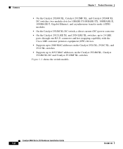
Chapter 1 Product Overview Figure 1-6 Catalyst 2912MF XL, 2924M XL, and 2924M XL DC LEDs 10BASE-FX port LEDs Front-Panel Description 12 1 MODE 2 3 4 5 100BASE-FX 6 7 System LED RPS LED Expansion slot status LED Port mode LED Mode button 48003 78-6461-04 Catalyst 2900 Series XL Hardware Installation Guide 1-11
Chapter 1 Product Overview Figure 1-6 Catalyst 2912MF XL, 2924M XL, and 2924M XL DC LEDs 10BASE-FX port LEDs Front-Panel Description 12 1 MODE 2 3 4 5 100BASE-FX 6 7 System LED RPS LED Expansion slot status LED Port mode LED Mode button 48003 78-6461-04 Catalyst 2900 Series XL Hardware Installation Guide 1-11
Hardware Installation Guide
Page 33
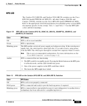
... XL, 2924 XL, 2924MF XL, 2924M XL, and 2924M XL DC Switches Color Off Green Blinking green Amber RPS Status RPS is not installed. Figure 1-8 RPS LED on the Catalyst 2912 LRE XL and 2924 LRE XL Switches Color Off Solid green Blinking green RPS Status RPS is off or is off or not properly connected. All other Catalyst 2900 XL and Catalyst 3500 XL switches use the Cisco...
... XL, 2924 XL, 2924MF XL, 2924M XL, and 2924M XL DC Switches Color Off Green Blinking green Amber RPS Status RPS is not installed. Figure 1-8 RPS LED on the Catalyst 2912 LRE XL and 2924 LRE XL Switches Color Off Solid green Blinking green RPS Status RPS is off or is off or not properly connected. All other Catalyst 2900 XL and Catalyst 3500 XL switches use the Cisco...

Hardware Installation Guide
Page 34
...port modes, the meaning of information displayed. Press the Standby/Active button on the Catalyst 2912 XL, 2924C XL, 2924 XL, 2924MF XL, 2924M XL, and 2924M XL DC Switches Mode LED STAT UTL FDUP 100 Port Mode Port status Switch utilization Port duplex mode Port speed Description The port status. When you change a... in standby mode or in a fault condition. The current bandwidth in a switch has failed, and the RPS is the default mode. Contact Cisco Systems. The internal power supply in use by the switch. (See Figure 1-8.) The port duplex mode: full duplex or half duplex,...
...port modes, the meaning of information displayed. Press the Standby/Active button on the Catalyst 2912 XL, 2924C XL, 2924 XL, 2924MF XL, 2924M XL, and 2924M XL DC Switches Mode LED STAT UTL FDUP 100 Port Mode Port status Switch utilization Port duplex mode Port speed Description The port status. When you change a... in standby mode or in a fault condition. The current bandwidth in a switch has failed, and the RPS is the default mode. Contact Cisco Systems. The internal power supply in use by the switch. (See Figure 1-8.) The port duplex mode: full duplex or half duplex,...

Hardware Installation Guide
Page 36
Port is operating at 10 Mbps. The LEDs display backplane utilization on . See Figure 1-8 for Different Modes on Catalyst 2912 XL, 2924C XL, 2924 XL, 2924MF XL, 2924M XL, and 2924M XL DC Switches Port Mode STAT (port status) Port LED Color Off Solid green Flashing green Alternating green-amber Solid amber UTL Green (utilization) FDUP (port duplex) 100 (...
Port is operating at 10 Mbps. The LEDs display backplane utilization on . See Figure 1-8 for Different Modes on Catalyst 2912 XL, 2924C XL, 2924 XL, 2924MF XL, 2924M XL, and 2924M XL DC Switches Port Mode STAT (port status) Port LED Color Off Solid green Flashing green Alternating green-amber Solid amber UTL Green (utilization) FDUP (port duplex) 100 (...
Hardware Installation Guide
Page 39
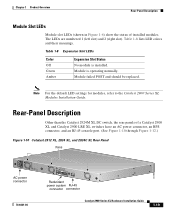
... is installed. Rear-Panel Description Other than the Catalyst 2924M XL DC switch, the rear panels of installed modules. Module failed POST and should be replaced. Note For the default LED settings for modules, refer to the Catalyst 2900 Series XL Modules Installation Guide. Table 1-8 Expansion Slot LEDs ... 1 Product Overview Rear-Panel Description Module Slot LEDs Module slot LEDs (shown in Figure 1-6) show the status of a Catalyst 2900 XL and Catalyst 2900 LRE XL switches have an AC power connector, an RPS connector, and an RJ-45 console port. (See Figure 1-10 through Figure...
... is installed. Rear-Panel Description Other than the Catalyst 2924M XL DC switch, the rear panels of installed modules. Module failed POST and should be replaced. Note For the default LED settings for modules, refer to the Catalyst 2900 Series XL Modules Installation Guide. Table 1-8 Expansion Slot LEDs ... 1 Product Overview Rear-Panel Description Module Slot LEDs Module slot LEDs (shown in Figure 1-6) show the status of a Catalyst 2900 XL and Catalyst 2900 LRE XL switches have an AC power connector, an RPS connector, and an RJ-45 console port. (See Figure 1-10 through Figure...
Hardware Installation Guide
Page 40
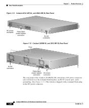
... connector CONSOLE RJ-45 connector Figure 1-12 Catalyst 2924M XL and 2912 MF XL Rear Panel Fans CONSOLE RJ-45 connector +5DVSCPINEPCPO@IUWF9TIAEES,[email protected] DC INPUT 21.000A-/11R2.0A0AT/2IN050G0--26400HVZ~ 47296 Redundant power system AC power connector connector The rear panel of the Catalyst 2924M XL DC switch has a DC power connector (also referred to as...
... connector CONSOLE RJ-45 connector Figure 1-12 Catalyst 2924M XL and 2912 MF XL Rear Panel Fans CONSOLE RJ-45 connector +5DVSCPINEPCPO@IUWF9TIAEES,[email protected] DC INPUT 21.000A-/11R2.0A0AT/2IN050G0--26400HVZ~ 47296 Redundant power system AC power connector connector The rear panel of the Catalyst 2924M XL DC switch has a DC power connector (also referred to as...
Hardware Installation Guide
Page 41
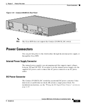
...-OR-ed into a single power block. DC Power Connector The Catalyst 2924M XL DC switch has an internal DC-power converter. For installation instructions, see the "Wiring the DC-Input Power Source" section on page 2-29. 78-6461-04 Catalyst 2900 Series XL Hardware Installation Guide 1-21 Note The Cisco RPS does not support the Catalyst 2924M XL DC switch. If you plan to use the...
...-OR-ed into a single power block. DC Power Connector The Catalyst 2924M XL DC switch has an internal DC-power converter. For installation instructions, see the "Wiring the DC-Input Power Source" section on page 2-29. 78-6461-04 Catalyst 2900 Series XL Hardware Installation Guide 1-21 Note The Cisco RPS does not support the Catalyst 2924M XL DC switch. If you plan to use the...
Hardware Installation Guide
Page 42
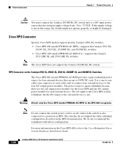
... modules. Cisco RPS Connector Specific Cisco RPS models support specific Catalyst 2900 XL switches: • Cisco RPS 600 (model PWR600-AC-RPS)-supports the Catalyst 2912 XL, 2924C XL, 2924 XL, 2924MF XL, and 2924M XL switches. • Cisco RPS 300 (model PWR300-AC-RPS-N1)-supports the Catalyst 2912 LRE XL and 2924 LRE XL switches Note The Cisco RPS does not support the Catalyst 2924M XL DC switch. Warning Attach only the Cisco RPS...
... modules. Cisco RPS Connector Specific Cisco RPS models support specific Catalyst 2900 XL switches: • Cisco RPS 600 (model PWR600-AC-RPS)-supports the Catalyst 2912 XL, 2924C XL, 2924 XL, 2924MF XL, and 2924M XL switches. • Cisco RPS 300 (model PWR300-AC-RPS-N1)-supports the Catalyst 2912 LRE XL and 2924 LRE XL switches Note The Cisco RPS does not support the Catalyst 2924M XL DC switch. Warning Attach only the Cisco RPS...
Hardware Installation Guide
Page 52
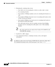
... guide does not attach to the Catalyst 2912 LRE XL and 2924 LRE XL switches. • One RJ-45-to-DB-9 adapter • Cisco Information Packet, containing warranty, safety, and support information Note In addition to the switch (19-inch rack mount) - ... Four rubber feet for mounting the switch on the switch back panel. (See Figure 1-13.) Catalyst 2900 Series XL Hardware Installation Guide 2-8 78-6461-04 Preparing for Installation Chapter 2 Installation • Mounting kit containing these items, the Catalyst 2924M XL DC switch also ships with a DC terminal block plug on a table...
... guide does not attach to the Catalyst 2912 LRE XL and 2924 LRE XL switches. • One RJ-45-to-DB-9 adapter • Cisco Information Packet, containing warranty, safety, and support information Note In addition to the switch (19-inch rack mount) - ... Four rubber feet for mounting the switch on the switch back panel. (See Figure 1-13.) Catalyst 2900 Series XL Hardware Installation Guide 2-8 78-6461-04 Preparing for Installation Chapter 2 Installation • Mounting kit containing these items, the Catalyst 2924M XL DC switch also ships with a DC terminal block plug on a table...
Hardware Installation Guide
Page 54
..." rack 23" rack mount point mount point To install the switch in these procedures: • "Removing Screws from the Switch" section on page 2-11 • "Attaching the Brackets to a Catalyst 2912 XL, 2924C XL, 2924 XL, 2912MF XL, 2924M XL, or 2924M XL DC Switch" section on page 2-11 2-10 Catalyst 2900 Series XL Hardware Installation Guide 78-6461-04 or 24-inch standard rack...
..." rack 23" rack mount point mount point To install the switch in these procedures: • "Removing Screws from the Switch" section on page 2-11 • "Attaching the Brackets to a Catalyst 2912 XL, 2924C XL, 2924 XL, 2912MF XL, 2924M XL, or 2924M XL DC Switch" section on page 2-11 2-10 Catalyst 2900 Series XL Hardware Installation Guide 78-6461-04 or 24-inch standard rack...
Hardware Installation Guide
Page 55
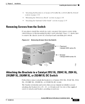
... on page 2-19 Removing Screws from the Switch Catalyst 2900 SERIES XL Fixed-port Catalyst 2900 series XL Catalyst 2900 SERIES XL 22X 23X 24X Modular Catalyst 2900 series XL 47292 Attaching the Brackets to a Catalyst 2912 XL, 2924C XL, 2924 XL, 2912MF XL, 2924M XL, or 2924M XL DC Switch Follow these steps to attach the brackets to a Catalyst 2912 XL, 2924C XL, 2924 XL, 2912MF XL, 2924M XL, or 2924M XL DC switch: The bracket orientation and screws that...
... on page 2-19 Removing Screws from the Switch Catalyst 2900 SERIES XL Fixed-port Catalyst 2900 series XL Catalyst 2900 SERIES XL 22X 23X 24X Modular Catalyst 2900 series XL 47292 Attaching the Brackets to a Catalyst 2912 XL, 2924C XL, 2924 XL, 2912MF XL, 2924M XL, or 2924M XL DC Switch Follow these steps to attach the brackets to a Catalyst 2912 XL, 2924C XL, 2924 XL, 2912MF XL, 2924M XL, or 2924M XL DC switch: The bracket orientation and screws that...
Hardware Installation Guide
Page 57
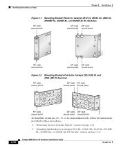
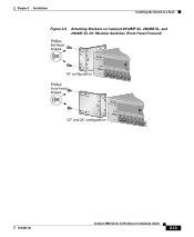
Chapter 2 Installation Installing the Switch in a Rack Figure 2-5 Attaching Brackets on Catalyst 2912MF XL, 2924M XL, and 2924M XL DC Modular Switches (Front-Panel Forward) Phillips flat-head screws 19" configuration Phillips truss-head screws 12 MODE 1X 2X 3X 4X 5X 6X 7X 23" and 24" configuration 12 MODE 1X 2X 3X 4X 5X 6X 7X 47297 78-6461-04 Catalyst 2900 Series XL Hardware Installation Guide 2-13
Chapter 2 Installation Installing the Switch in a Rack Figure 2-5 Attaching Brackets on Catalyst 2912MF XL, 2924M XL, and 2924M XL DC Modular Switches (Front-Panel Forward) Phillips flat-head screws 19" configuration Phillips truss-head screws 12 MODE 1X 2X 3X 4X 5X 6X 7X 23" and 24" configuration 12 MODE 1X 2X 3X 4X 5X 6X 7X 47297 78-6461-04 Catalyst 2900 Series XL Hardware Installation Guide 2-13
Hardware Installation Guide
Page 59
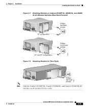
....0A0AT/2IN050G0--26400HVZ~ Phillips truss-head screws 23" and 24" configuration Figure 2-8 Attaching Brackets for Telco Racks 47299 DC INPUT 21.00A0-/11R2.0A0AT/2IN050G0--26400HVZ~ Phillips flat-head screws 71236 Note Only the Catalyst 2912MF XL, Catalyst 2924M XL, and Catalyst 2924M XL DC switches can be mounted in telco racks. 78-6461-04 Catalyst 2900 Series XL Hardware Installation Guide 2-15
....0A0AT/2IN050G0--26400HVZ~ Phillips truss-head screws 23" and 24" configuration Figure 2-8 Attaching Brackets for Telco Racks 47299 DC INPUT 21.00A0-/11R2.0A0AT/2IN050G0--26400HVZ~ Phillips flat-head screws 71236 Note Only the Catalyst 2912MF XL, Catalyst 2924M XL, and Catalyst 2924M XL DC switches can be mounted in telco racks. 78-6461-04 Catalyst 2900 Series XL Hardware Installation Guide 2-15

Hardware Installation Guide
Page 69
...As each turn off. If a test fails, the port LED associated with a DC terminal block plug on the switch back panel. Connecting to DC Power To connect the Catalyst 2924M XL DC switch to 8 each test runs, the port LEDs, starting with optional controlled cycle ...mechanism, model CT-700, CT-720, CT-920, CT-930, CT-920CH, or CT-940CH • 6-gauge copper ground wire (insulated or noninsulated) 78-6461-04 Catalyst 2900 Series XL Hardware Installation Guide 2-25 Call Cisco...
...As each turn off. If a test fails, the port LED associated with a DC terminal block plug on the switch back panel. Connecting to DC Power To connect the Catalyst 2924M XL DC switch to 8 each test runs, the port LEDs, starting with optional controlled cycle ...mechanism, model CT-700, CT-720, CT-920, CT-930, CT-920CH, or CT-940CH • 6-gauge copper ground wire (insulated or noninsulated) 78-6461-04 Catalyst 2900 Series XL Hardware Installation Guide 2-25 Call Cisco...

Hardware Installation Guide
Page 103
Appendix A Technical Specifications 78-6461-04 Table A-4 Technical Specifications for Catalyst 2924M XL DC Switches Environmental Ranges Operating temperature Storage temperature Operating humidity Operating altitude Storage altitude Power Requirements Power consumption DC input voltage Wire gauge for the Catalyst 2912 LRE XL and 2924 LRE XL Switches Environmental Operating Ranges Operating temperature Storage temperature Operating humidity Operating altitude Storage altitude Power...
Appendix A Technical Specifications 78-6461-04 Table A-4 Technical Specifications for Catalyst 2924M XL DC Switches Environmental Ranges Operating temperature Storage temperature Operating humidity Operating altitude Storage altitude Power Requirements Power consumption DC input voltage Wire gauge for the Catalyst 2912 LRE XL and 2924 LRE XL Switches Environmental Operating Ranges Operating temperature Storage temperature Operating humidity Operating altitude Storage altitude Power...

Hardware Installation Guide
Page 104
... Table A-5 Technical Specifications for the Catalyst 2912 LRE XL and 2924 LRE XL Switches (continued) AC input voltage 100 to 127/200 to 240 VAC (autoranging) 50 to 60 Hz DC input voltages +12V @12A Power consumption 70W Physical Dimensions Weight • Catalyst 2912 LRE XL 8.75 lb (4 kg) • Catalyst 2924 LRE XL 10.75 lb (4.88 kg... 3260, TS001 CE EMI FCC Part 15 Class A EN 55022 Class A (CISPR 22 Class A) VCCI Class A AS/NZS 3548 Class A BCIQ CE Table A-7 Agency Approvals (Catalyst 2924M XL DC Switch) Safety NOM 019 BSMI EMC EN 50082-1 Class A BSMI NEBS GR-1089 GR-63...
... Table A-5 Technical Specifications for the Catalyst 2912 LRE XL and 2924 LRE XL Switches (continued) AC input voltage 100 to 127/200 to 240 VAC (autoranging) 50 to 60 Hz DC input voltages +12V @12A Power consumption 70W Physical Dimensions Weight • Catalyst 2912 LRE XL 8.75 lb (4 kg) • Catalyst 2924 LRE XL 10.75 lb (4.88 kg... 3260, TS001 CE EMI FCC Part 15 Class A EN 55022 Class A (CISPR 22 Class A) VCCI Class A AS/NZS 3548 Class A BCIQ CE Table A-7 Agency Approvals (Catalyst 2924M XL DC Switch) Safety NOM 019 BSMI EMC EN 50082-1 Class A BSMI NEBS GR-1089 GR-63...
Hardware Installation Guide
Page 142
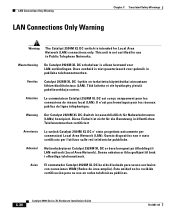
...). Diese Einheit ist nicht für die Benutzung in öffentlichen Telefonnetzwerken zertifiziert Avvertenza Lo switch Catalyst 2924M XL DC e' stato progettato unicamente per l'utilizzo sulle reti telefoniche pubbliche. Waarschuwing De Catalyst 2924M XL DC schakelaar is intended for use in publieke telefoonnetwerken. Aviso El conmutador Catalyst 2924M XL DC ha sido diseñado para su uso exclusivo con conexiones WAN (Redes de...
...). Diese Einheit ist nicht für die Benutzung in öffentlichen Telefonnetzwerken zertifiziert Avvertenza Lo switch Catalyst 2924M XL DC e' stato progettato unicamente per l'utilizzo sulle reti telefoniche pubbliche. Waarschuwing De Catalyst 2924M XL DC schakelaar is intended for use in publieke telefoonnetwerken. Aviso El conmutador Catalyst 2924M XL DC ha sido diseñado para su uso exclusivo con conexiones WAN (Redes de...

