Hardware Installation Guide
Page 6
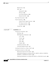
... Cisco RPS Connector 1-22 Console Port 1-23 2 C H A P T E R Installation 2-1 Preparing for Installation 2-1 Warnings 2-1 EMC Regulatory Statements 2-4 U.S.A. 2-4 Taiwan 2-4 Japan 2-5 Korea 2-5 Hungary 2-6 Installation Guidelines 2-6 Verifying Package Contents 2-7 Installing the Switch on a Table or Shelf 2-9 Installing the Switch in a Rack 2-9 Removing Screws from the Switch 2-11 Attaching the Brackets to a Catalyst 2912 XL, 2924C XL, 2924 XL, 2912MF XL, 2924M XL...
... Cisco RPS Connector 1-22 Console Port 1-23 2 C H A P T E R Installation 2-1 Preparing for Installation 2-1 Warnings 2-1 EMC Regulatory Statements 2-4 U.S.A. 2-4 Taiwan 2-4 Japan 2-5 Korea 2-5 Hungary 2-6 Installation Guidelines 2-6 Verifying Package Contents 2-7 Installing the Switch on a Table or Shelf 2-9 Installing the Switch in a Rack 2-9 Removing Screws from the Switch 2-11 Attaching the Brackets to a Catalyst 2912 XL, 2924C XL, 2924 XL, 2912MF XL, 2924M XL...

Hardware Installation Guide
Page 30
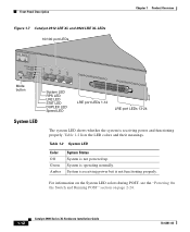
... use CMS to manage standalone or individual switches and how to use cluster management software to manage switch clusters]. Figure 1-5 Catalyst 2912 XL, 2924 XL, and 2924C XL LEDs 10/100 port LEDs System LED Port mode LEDs MODE 1X 2X 3X 4X 5X 6X 7X Mode RPS button LED 47288 1-10 Catalyst 2900 Series XL Hardware Installation Guide 78...
... use CMS to manage standalone or individual switches and how to use cluster management software to manage switch clusters]. Figure 1-5 Catalyst 2912 XL, 2924 XL, and 2924C XL LEDs 10/100 port LEDs System LED Port mode LEDs MODE 1X 2X 3X 4X 5X 6X 7X Mode RPS button LED 47288 1-10 Catalyst 2900 Series XL Hardware Installation Guide 78...
Hardware Installation Guide
Page 32
... Switch and Running POST" section on page 2-24. 1-12 Catalyst 2900 Series XL Hardware Installation Guide 78-6461-04 System is receiving power but is operating normally. Table 1-2 System LED Color Off Green Amber System Status System is receiving power and functioning properly. Front-Panel Description Figure 1-7 Catalyst 2912 LRE XL and 2924 LRE XL LEDs...
... Switch and Running POST" section on page 2-24. 1-12 Catalyst 2900 Series XL Hardware Installation Guide 78-6461-04 System is receiving power but is operating normally. Table 1-2 System LED Color Off Green Amber System Status System is receiving power and functioning properly. Front-Panel Description Figure 1-7 Catalyst 2912 LRE XL and 2924 LRE XL LEDs...
Hardware Installation Guide
Page 33
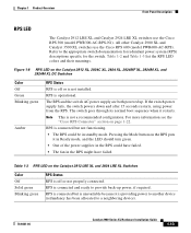
... RPS is off or is not installed. Table 1-3 RPS LED on the Catalyst 2912 XL, 2924C XL, 2924 XL, 2924MF XL, 2924M XL, and 2924M XL DC Switches Color Off Green Blinking green Amber RPS Status RPS is providing... power to another device (redundancy has been allocated to a neighboring device). 78-6461-04 Catalyst 2900 Series XL Hardware Installation Guide 1-13 Chapter 1 Product Overview Front-Panel Description RPS LED The Catalyst 2912 LRE XL and Catalyst 2924 LRE XL switches use the Cisco...
... RPS is off or is not installed. Table 1-3 RPS LED on the Catalyst 2912 XL, 2924C XL, 2924 XL, 2924MF XL, 2924M XL, and 2924M XL DC Switches Color Off Green Blinking green Amber RPS Status RPS is providing... power to another device (redundancy has been allocated to a neighboring device). 78-6461-04 Catalyst 2900 Series XL Hardware Installation Guide 1-13 Chapter 1 Product Overview Front-Panel Description RPS LED The Catalyst 2912 LRE XL and Catalyst 2924 LRE XL switches use the Cisco...

Hardware Installation Guide
Page 34
... the RPS is the default mode. Press the Standby/Active button on the Catalyst 2912 XL, 2924C XL, 2924 XL, 2924MF XL, 2924M XL, and 2924M XL DC Switches Mode LED STAT UTL FDUP 100 Port Mode Port status Switch utilization Port duplex mode Port speed Description The port status. If it does...or in a fault condition. Table 1-6 and Table 1-7 list the port LED colors. This is providing power to the switch (redundancy has been allocated to this device). Contact Cisco Systems. The internal power supply in use by the switch. (See Figure 1-8.) The port duplex mode: full duplex or half duplex,...
... the RPS is the default mode. Press the Standby/Active button on the Catalyst 2912 XL, 2924C XL, 2924 XL, 2924MF XL, 2924M XL, and 2924M XL DC Switches Mode LED STAT UTL FDUP 100 Port Mode Port status Switch utilization Port duplex mode Port speed Description The port status. If it does...or in a fault condition. Table 1-6 and Table 1-7 list the port LED colors. This is providing power to the switch (redundancy has been allocated to this device). Contact Cisco Systems. The internal power supply in use by the switch. (See Figure 1-8.) The port duplex mode: full duplex or half duplex,...

Hardware Installation Guide
Page 35
... Installation Guide 1-15 Default mode on all Catalyst 2900 XL and Catalyst 3500 XL switches except the Catalyst 2912 LRE XL and Catalyst 2924 LRE XL switches. The default setting is half duplex. Chapter 1 Product Overview Front-Panel Description Table 1-5 Port Mode LEDs on Catalyst 2912 LRE XL and 2924 LRE XL Switches Mode LED LRE STAT DUPLX SPEED Port Mode LRE...
... Installation Guide 1-15 Default mode on all Catalyst 2900 XL and Catalyst 3500 XL switches except the Catalyst 2912 LRE XL and Catalyst 2924 LRE XL switches. The default setting is half duplex. Chapter 1 Product Overview Front-Panel Description Table 1-5 Port Mode LEDs on Catalyst 2912 LRE XL and 2924 LRE XL Switches Mode LED LRE STAT DUPLX SPEED Port Mode LRE...

Hardware Installation Guide
Page 36
... monitored for details. Port is reconfigured, the port LED can affect connectivity, and errors such as STP checks the switch for Different Modes on Catalyst 2912 XL, 2924C XL, 2924 XL, 2924MF XL, 2924M XL, and 2924M XL DC Switches Port Mode STAT (port status) Port LED Color Off Solid green Flashing green Alternating green-amber Solid amber...
... monitored for details. Port is reconfigured, the port LED can affect connectivity, and errors such as STP checks the switch for Different Modes on Catalyst 2912 XL, 2924C XL, 2924 XL, 2924MF XL, 2924M XL, and 2924M XL DC Switches Port Mode STAT (port status) Port LED Color Off Solid green Flashing green Alternating green-amber Solid amber...

Hardware Installation Guide
Page 37
...LRE port, or the port is operating in STP forwarding state. Cyan (off) No LRE link present on the LRE port. DUPLX Blinking amber Cisco IOS Release 12.0(5.x)WC1/ WC21 Activity on the LRE port. Green LRE port or remote CPE Ethernet port is reconfigured, the port... from those on the LRE port. See Table 1-5 for LED information about the 10/100 ports. Green LRE link present on Catalyst 2912 LRE XL and 2924 LRE XL Switches Port Mode Port LED Color Description LRE Note In LRE mode, the 10/100 switch port LEDs continue to a LRE CPE. Chapter 1 Product Overview Front-...
...LRE port, or the port is operating in STP forwarding state. Cyan (off) No LRE link present on the LRE port. DUPLX Blinking amber Cisco IOS Release 12.0(5.x)WC1/ WC21 Activity on the LRE port. Green LRE port or remote CPE Ethernet port is reconfigured, the port... from those on the LRE port. See Table 1-5 for LED information about the 10/100 ports. Green LRE link present on Catalyst 2912 LRE XL and 2924 LRE XL Switches Port Mode Port LED Color Description LRE Note In LRE mode, the 10/100 switch port LEDs continue to a LRE CPE. Chapter 1 Product Overview Front-...
Hardware Installation Guide
Page 38
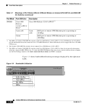
... Release 12.0(5.x)WC4 or later do not provide information about the connected Cisco 575 LRE CPE devices. The LEDs on Catalyst 2912 LRE XL and 2924 LRE XL Switches (continued) Port Mode SPEED Port LED Color Cisco IOS Release 12.0(5.x)WC1/ WC21 Description Cisco IOS Release 12.0(5.x)WC42 3 Cyan (off) Cyan (off) LRE port or remote CPE Ethernet...
... Release 12.0(5.x)WC4 or later do not provide information about the connected Cisco 575 LRE CPE devices. The LEDs on Catalyst 2912 LRE XL and 2924 LRE XL Switches (continued) Port Mode SPEED Port LED Color Cisco IOS Release 12.0(5.x)WC1/ WC21 Description Cisco IOS Release 12.0(5.x)WC42 3 Cyan (off) Cyan (off) LRE port or remote CPE Ethernet...
Hardware Installation Guide
Page 39
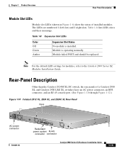
....) Figure 1-10 Catalyst 2912 XL, 2924 XL, and 2924C XL Rear Panel Fans 47295 11.000A-/1O2R.75A/AT2I0N50G0-2-8400HV~Z AC power connector +5DVSCPIENPCPO@IUWF9TIAEES,[email protected] CONSOLE Redundant power system RJ-45 connector connector 78-6461-04 Catalyst 2900 Series XL ...Hardware Installation Guide 1-19 Module failed POST and should be replaced. Table 1-8 Expansion Slot LEDs Color Off Green Amber Expansion Slot Status No module is operating normally. Rear-Panel Description Other than the Catalyst 2924M XL DC switch, the rear...
....) Figure 1-10 Catalyst 2912 XL, 2924 XL, and 2924C XL Rear Panel Fans 47295 11.000A-/1O2R.75A/AT2I0N50G0-2-8400HV~Z AC power connector +5DVSCPIENPCPO@IUWF9TIAEES,[email protected] CONSOLE Redundant power system RJ-45 connector connector 78-6461-04 Catalyst 2900 Series XL ...Hardware Installation Guide 1-19 Module failed POST and should be replaced. Table 1-8 Expansion Slot LEDs Color Off Green Amber Expansion Slot Status No module is operating normally. Rear-Panel Description Other than the Catalyst 2924M XL DC switch, the rear...

