Hardware Installation Guide
Page 33
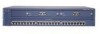
...switch. The switch goes through its normal boot sequence when it in Ready mode, and the LED should turn green. • One of the power supplies in the RPS could be in the RPS might have failed. • The fan...is operational. Table 1-3 RPS LED on the Catalyst 2912 XL, 2924C XL, 2924 XL, 2924MF XL, 2924M XL, and 2924M XL DC Switches Color Off Green Blinking green Amber RPS Status .... Chapter 1 Product Overview Front-Panel Description RPS LED The Catalyst 2912 LRE XL and Catalyst 2924 LRE XL switches use the Cisco RPS 600 (model PWR600-AC-RPS). Pressing the Mode button...
...switch. The switch goes through its normal boot sequence when it in Ready mode, and the LED should turn green. • One of the power supplies in the RPS could be in the RPS might have failed. • The fan...is operational. Table 1-3 RPS LED on the Catalyst 2912 XL, 2924C XL, 2924 XL, 2924MF XL, 2924M XL, and 2924M XL DC Switches Color Off Green Blinking green Amber RPS Status .... Chapter 1 Product Overview Front-Panel Description RPS LED The Catalyst 2912 LRE XL and Catalyst 2924 LRE XL switches use the Cisco RPS 600 (model PWR600-AC-RPS). Pressing the Mode button...

Hardware Installation Guide
Page 34
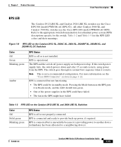
...Description Chapter 1 Product Overview Table 1-3 RPS LED on the Catalyst 2912 LRE XL and 2924 LRE XL Switches (continued) Color Solid amber Blinking amber RPS Status The RPS is highlighted. If it does not, the RPS fan could have a port LED. Contact Cisco Systems. The internal power supply in use by the... and module slots have failed. The current bandwidth in a switch has failed, and the RPS is the default mode. Press the Standby/Active button on the Catalyst 2912 XL, 2924C XL, 2924 XL, 2924MF XL, 2924M XL, and 2924M XL DC Switches Mode LED STAT UTL FDUP 100 Port Mode Port status...
...Description Chapter 1 Product Overview Table 1-3 RPS LED on the Catalyst 2912 LRE XL and 2924 LRE XL Switches (continued) Color Solid amber Blinking amber RPS Status The RPS is highlighted. If it does not, the RPS fan could have a port LED. Contact Cisco Systems. The internal power supply in use by the... and module slots have failed. The current bandwidth in a switch has failed, and the RPS is the default mode. Press the Standby/Active button on the Catalyst 2912 XL, 2924C XL, 2924 XL, 2924MF XL, 2924M XL, and 2924M XL DC Switches Mode LED STAT UTL FDUP 100 Port Mode Port status...
Hardware Installation Guide
Page 39
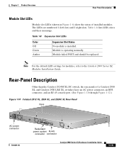
... Table 1-8 Expansion Slot LEDs Color Off Green Amber Expansion Slot Status No module is operating normally. Rear-Panel Description Other than the Catalyst 2924M XL DC switch, the rear panels of installed modules. Chapter 1 Product Overview Rear-Panel Description Module Slot LEDs Module slot LEDs (shown in Figure ... XL and Catalyst 2900 LRE XL switches have an AC power connector, an RPS connector, and an RJ-45 console port. (See Figure 1-10 through Figure 1-12.) Figure 1-10 Catalyst 2912 XL, 2924 XL, and 2924C XL Rear Panel Fans 47295 11.000A-/1O2R.75A/AT2I0N50G0-2-8400HV~Z AC power...
... Table 1-8 Expansion Slot LEDs Color Off Green Amber Expansion Slot Status No module is operating normally. Rear-Panel Description Other than the Catalyst 2924M XL DC switch, the rear panels of installed modules. Chapter 1 Product Overview Rear-Panel Description Module Slot LEDs Module slot LEDs (shown in Figure ... XL and Catalyst 2900 LRE XL switches have an AC power connector, an RPS connector, and an RJ-45 console port. (See Figure 1-10 through Figure 1-12.) Figure 1-10 Catalyst 2912 XL, 2924 XL, and 2924C XL Rear Panel Fans 47295 11.000A-/1O2R.75A/AT2I0N50G0-2-8400HV~Z AC power...
Hardware Installation Guide
Page 40
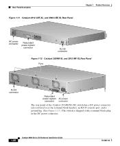
...Catalyst 2912 LRE XL, and 2924 LRE XL Rear Panel Chapter 1 Product Overview 48004 100-240V~ 5-3A 50/60Hz MAXIMUM 300W TOTAL OUTPUT DC OUTPUT AC power connector Redundant power system connector CONSOLE RJ-45 connector Figure 1-12 Catalyst 2924M XL and 2912 MF XL Rear Panel Fans... CONSOLE RJ-45 connector +5DVSCPINEPCPO@IUWF9TIAEES,[email protected] DC INPUT 21.000A-/11R2.0A0AT/2IN050G0--26400HVZ~ 47296 Redundant power system AC power connector connector The rear panel of the Catalyst 2924M XL DC switch has a...
...Catalyst 2912 LRE XL, and 2924 LRE XL Rear Panel Chapter 1 Product Overview 48004 100-240V~ 5-3A 50/60Hz MAXIMUM 300W TOTAL OUTPUT DC OUTPUT AC power connector Redundant power system connector CONSOLE RJ-45 connector Figure 1-12 Catalyst 2924M XL and 2912 MF XL Rear Panel Fans... CONSOLE RJ-45 connector +5DVSCPINEPCPO@IUWF9TIAEES,[email protected] DC INPUT 21.000A-/11R2.0A0AT/2IN050G0--26400HVZ~ 47296 Redundant power system AC power connector connector The rear panel of the Catalyst 2924M XL DC switch has a...
Hardware Installation Guide
Page 61
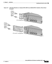
Chapter 2 Installation Installing the Switch in a Rack Figure 2-9 Attaching Brackets on Catalyst 2912 LRE XL and 2924 LRE XL Switches (Front-Panel Forward) Phillips flat-head screws Phillips truss-head screws 19" configuration INPUT OUTPUT PWR PWR RESET TEMP FAN 9X 10X 11X 12X 23" and 24" configuration INPUT OUTPUT PWR PWR RESET TEMP FAN 9X 10X 11X 12X 54728 78-6461-04 Catalyst 2900 Series XL Hardware Installation Guide 2-17
Chapter 2 Installation Installing the Switch in a Rack Figure 2-9 Attaching Brackets on Catalyst 2912 LRE XL and 2924 LRE XL Switches (Front-Panel Forward) Phillips flat-head screws Phillips truss-head screws 19" configuration INPUT OUTPUT PWR PWR RESET TEMP FAN 9X 10X 11X 12X 23" and 24" configuration INPUT OUTPUT PWR PWR RESET TEMP FAN 9X 10X 11X 12X 54728 78-6461-04 Catalyst 2900 Series XL Hardware Installation Guide 2-17
