
Hardware Installation Guide
Page 30
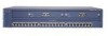
...Catalyst 2912 XL, 2924 XL, and 2924C XL LEDs 10/100 port LEDs System LED Port mode LEDs MODE 1X 2X 3X 4X 5X 6X 7X Mode RPS button LED 47288 1-10 Catalyst 2900 Series XL Hardware Installation Guide 78-6461-04 The Catalyst 2900 Series XL and Catalyst 3500 Series XL Software Configuration... Guide describes how to use CMS to manage standalone or individual switches and how to use cluster management software to manage switch clusters]. Front-Panel Description Chapter 1 ...
...Catalyst 2912 XL, 2924 XL, and 2924C XL LEDs 10/100 port LEDs System LED Port mode LEDs MODE 1X 2X 3X 4X 5X 6X 7X Mode RPS button LED 47288 1-10 Catalyst 2900 Series XL Hardware Installation Guide 78-6461-04 The Catalyst 2900 Series XL and Catalyst 3500 Series XL Software Configuration... Guide describes how to use CMS to manage standalone or individual switches and how to use cluster management software to manage switch clusters]. Front-Panel Description Chapter 1 ...
Hardware Installation Guide
Page 33
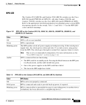
... is not a recommended configuration. Note This is operational. RPS is off or not properly connected. Chapter 1 Product Overview Front-Panel Description RPS LED The Catalyst 2912 LRE XL and Catalyst 2924 LRE XL switches use the Cisco RPS 600 (model PWR600-AC-RPS). The switch goes through its normal ...boot sequence when it is not installed. Pressing the Mode button on the Catalyst 2912 XL, 2924C XL, 2924 XL, 2924MF XL, 2924M XL, and 2924M XL DC Switches...
... is not a recommended configuration. Note This is operational. RPS is off or not properly connected. Chapter 1 Product Overview Front-Panel Description RPS LED The Catalyst 2912 LRE XL and Catalyst 2924 LRE XL switches use the Cisco RPS 600 (model PWR600-AC-RPS). The switch goes through its normal ...boot sequence when it is not installed. Pressing the Mode button on the Catalyst 2912 XL, 2924C XL, 2924 XL, 2924MF XL, 2924M XL, and 2924M XL DC Switches...
Hardware Installation Guide
Page 42
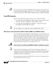
RPS Connector on the Catalyst 2912 XL, 2924C XL, 2924 XL, 2924MF XL, and 2924M XL Switches The Cisco RPS 600 (model PWR600-AC-RPS) provides a quasi-redundant power source for each external device. The switches do not recommend the redundant-with-reboot configuration. The AC input to the Cisco RPS is fully redundant, but the DC output to...
RPS Connector on the Catalyst 2912 XL, 2924C XL, 2924 XL, 2924MF XL, and 2924M XL Switches The Cisco RPS 600 (model PWR600-AC-RPS) provides a quasi-redundant power source for each external device. The switches do not recommend the redundant-with-reboot configuration. The AC input to the Cisco RPS is fully redundant, but the DC output to...
Hardware Installation Guide
Page 56
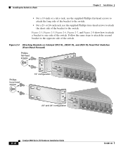
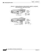
...head screws to attach the short side of the bracket to the switch. Figure 2-4 Attaching Brackets on Catalyst 2912 XL, 2924C XL, and 2924 XL Fixed-Port Switches (Front-Panel Forward) Phillips flat-head screws Phillips truss-head screws 19" configuration MODE 1X 2X 3X 4X 5X 6X 7X 47738 23" and... 24" configuration MODE 1X 2X 3X 4X 5X 6X 7X 2-12 Catalyst 2900 Series XL...
...head screws to attach the short side of the bracket to the switch. Figure 2-4 Attaching Brackets on Catalyst 2912 XL, 2924C XL, and 2924 XL Fixed-Port Switches (Front-Panel Forward) Phillips flat-head screws Phillips truss-head screws 19" configuration MODE 1X 2X 3X 4X 5X 6X 7X 47738 23" and... 24" configuration MODE 1X 2X 3X 4X 5X 6X 7X 2-12 Catalyst 2900 Series XL...
Hardware Installation Guide
Page 58
Installing the Switch in a Rack Chapter 2 Installation Figure 2-6 Attaching Brackets on Catalyst 2912 XL, 2924C XL, and 2924 XL Fixed-Port Switches (Rear-Panel Forward) 19" configuration Phillips flat-head screws 23" and 24" configuration Phillips truss-head screws 47298 2-14 Catalyst 2900 Series XL Hardware Installation Guide 78-6461-04
Installing the Switch in a Rack Chapter 2 Installation Figure 2-6 Attaching Brackets on Catalyst 2912 XL, 2924C XL, and 2924 XL Fixed-Port Switches (Rear-Panel Forward) 19" configuration Phillips flat-head screws 23" and 24" configuration Phillips truss-head screws 47298 2-14 Catalyst 2900 Series XL Hardware Installation Guide 78-6461-04
Hardware Installation Guide
Page 61
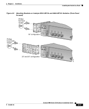
Chapter 2 Installation Installing the Switch in a Rack Figure 2-9 Attaching Brackets on Catalyst 2912 LRE XL and 2924 LRE XL Switches (Front-Panel Forward) Phillips flat-head screws Phillips truss-head screws 19" configuration INPUT OUTPUT PWR PWR RESET TEMP FAN 9X 10X 11X 12X 23" and 24" configuration INPUT OUTPUT PWR PWR RESET TEMP FAN 9X 10X 11X 12X 54728 78-6461-04 Catalyst 2900 Series XL Hardware Installation Guide 2-17
Chapter 2 Installation Installing the Switch in a Rack Figure 2-9 Attaching Brackets on Catalyst 2912 LRE XL and 2924 LRE XL Switches (Front-Panel Forward) Phillips flat-head screws Phillips truss-head screws 19" configuration INPUT OUTPUT PWR PWR RESET TEMP FAN 9X 10X 11X 12X 23" and 24" configuration INPUT OUTPUT PWR PWR RESET TEMP FAN 9X 10X 11X 12X 54728 78-6461-04 Catalyst 2900 Series XL Hardware Installation Guide 2-17

Hardware Installation Guide
Page 62
Installing the Switch in a Rack Chapter 2 Installation Figure 2-10 Attaching Brackets on Catalyst 2912 LRE XL and 2924 LRE XL Switches (Rear-Panel Forward 19" configuration Phillips flat-head screws 54824 Phillips truss-head screws 23" and 24" configuration Mounting the Switch in a Rack After the brackets are attached to the switch, use the four supplied number-12 Phillips machine screws to securely attach the brackets to the rack, as shown in Figure 2-11. 2-18 Catalyst 2900 Series XL Hardware Installation Guide 78-6461-04
Installing the Switch in a Rack Chapter 2 Installation Figure 2-10 Attaching Brackets on Catalyst 2912 LRE XL and 2924 LRE XL Switches (Rear-Panel Forward 19" configuration Phillips flat-head screws 54824 Phillips truss-head screws 23" and 24" configuration Mounting the Switch in a Rack After the brackets are attached to the switch, use the four supplied number-12 Phillips machine screws to securely attach the brackets to the rack, as shown in Figure 2-11. 2-18 Catalyst 2900 Series XL Hardware Installation Guide 78-6461-04


