Hardware Installation Guide
Page 6
... Cisco RPS Connector 1-22 Console Port 1-23 2 C H A P T E R Installation 2-1 Preparing for Installation 2-1 Warnings 2-1 EMC Regulatory Statements 2-4 U.S.A. 2-4 Taiwan 2-4 Japan 2-5 Korea 2-5 Hungary 2-6 Installation Guidelines 2-6 Verifying Package Contents 2-7 Installing the Switch on a Table or Shelf 2-9 Installing the Switch in a Rack 2-9 Removing Screws from the Switch 2-11 Attaching the Brackets to a Catalyst 2912 XL, 2924C XL, 2924 XL, 2912MF XL, 2924M XL...
... Cisco RPS Connector 1-22 Console Port 1-23 2 C H A P T E R Installation 2-1 Preparing for Installation 2-1 Warnings 2-1 EMC Regulatory Statements 2-4 U.S.A. 2-4 Taiwan 2-4 Japan 2-5 Korea 2-5 Hungary 2-6 Installation Guidelines 2-6 Verifying Package Contents 2-7 Installing the Switch on a Table or Shelf 2-9 Installing the Switch in a Rack 2-9 Removing Screws from the Switch 2-11 Attaching the Brackets to a Catalyst 2912 XL, 2924C XL, 2924 XL, 2912MF XL, 2924M XL...
Hardware Installation Guide
Page 22
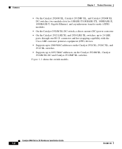
... hot swapping capability with the Cisco LRE customer premises equipment (CPE) devices • Supports up to 2048 MAC addresses on the Catalyst 2924 XL, 2924C XL, and 2912 XL switches • Supports up to 8192 MAC addresses on the Catalyst 2924M XL, Catalyst 2924M XL DC and Catalyst 2912MF XL switches Figure 1-1 shows the switch models. Catalyst 2900 Series XL Hardware Installation...
... hot swapping capability with the Cisco LRE customer premises equipment (CPE) devices • Supports up to 2048 MAC addresses on the Catalyst 2924 XL, 2924C XL, and 2912 XL switches • Supports up to 8192 MAC addresses on the Catalyst 2924M XL, Catalyst 2924M XL DC and Catalyst 2912MF XL switches Figure 1-1 shows the switch models. Catalyst 2900 Series XL Hardware Installation...

Hardware Installation Guide
Page 30
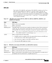
... utilization meter (UTL) are visible on the Cluster Management Suite (CMS) window and, if the switch is a cluster member, on the CMS Cluster Manager window. Figure 1-5 Catalyst 2912 XL, 2924 XL, and 2924C XL LEDs 10/100 port LEDs System LED Port mode LEDs MODE 1X 2X 3X 4X 5X 6X... 7X Mode RPS button LED 47288 1-10 Catalyst 2900 Series XL Hardware Installation Guide 78-6461-04 The Catalyst 2900 Series XL and Catalyst 3500 Series XL Software Configuration Guide describes how to use CMS to manage standalone or individual switches and how to use cluster management software to manage...
... utilization meter (UTL) are visible on the Cluster Management Suite (CMS) window and, if the switch is a cluster member, on the CMS Cluster Manager window. Figure 1-5 Catalyst 2912 XL, 2924 XL, and 2924C XL LEDs 10/100 port LEDs System LED Port mode LEDs MODE 1X 2X 3X 4X 5X 6X... 7X Mode RPS button LED 47288 1-10 Catalyst 2900 Series XL Hardware Installation Guide 78-6461-04 The Catalyst 2900 Series XL and Catalyst 3500 Series XL Software Configuration Guide describes how to use CMS to manage standalone or individual switches and how to use cluster management software to manage...
Hardware Installation Guide
Page 33
...The RPS could have failed. • The fan in standby mode. Chapter 1 Product Overview Front-Panel Description RPS LED The Catalyst 2912 LRE XL and Catalyst 2924 LRE XL switches use the Cisco RPS 600 (model PWR600-AC-RPS). Note This is operational. Table 1-3 RPS LED on page 1-22. The RPS and ... is connected but is unavailable because it is not installed. Pressing the Mode button on the Catalyst 2912 XL, 2924C XL, 2924 XL, 2924MF XL, 2924M XL, and 2924M XL DC Switches Color Off Green Blinking green Amber RPS Status RPS is connected and ready to provide back-up . RPS is ...
...The RPS could have failed. • The fan in standby mode. Chapter 1 Product Overview Front-Panel Description RPS LED The Catalyst 2912 LRE XL and Catalyst 2924 LRE XL switches use the Cisco RPS 600 (model PWR600-AC-RPS). Note This is operational. Table 1-3 RPS LED on page 1-22. The RPS and ... is connected but is unavailable because it is not installed. Pressing the Mode button on the Catalyst 2912 XL, 2924C XL, 2924 XL, 2924MF XL, 2924M XL, and 2924M XL DC Switches Color Off Green Blinking green Amber RPS Status RPS is connected and ready to provide back-up . RPS is ...

Hardware Installation Guide
Page 34
Press the Standby/Active button on the Catalyst 2912 XL, 2924C XL, 2924 XL, 2924MF XL, 2924M XL, and 2924M XL DC Switches Mode LED STAT UTL FDUP 100 Port Mode Port status Switch utilization Port duplex mode Port speed Description The port status. The port modes (Table 1-4 and...Cisco Systems. The internal power supply in a fault condition. To select or change port modes, the meaning of the port LED colors also changes. This is highlighted. Port LEDs and Modes Each of information displayed. Front-Panel Description Chapter 1 Product Overview Table 1-3 RPS LED on the Catalyst...
Press the Standby/Active button on the Catalyst 2912 XL, 2924C XL, 2924 XL, 2924MF XL, 2924M XL, and 2924M XL DC Switches Mode LED STAT UTL FDUP 100 Port Mode Port status Switch utilization Port duplex mode Port speed Description The port status. The port modes (Table 1-4 and...Cisco Systems. The internal power supply in a fault condition. To select or change port modes, the meaning of the port LED colors also changes. This is highlighted. Port LEDs and Modes Each of information displayed. Front-Panel Description Chapter 1 Product Overview Table 1-3 RPS LED on the Catalyst...

Hardware Installation Guide
Page 36
...Protocol (STP). If all port LEDs are monitored for possible loops. See Figure 1-8 for Different Modes on Catalyst 2912 XL, 2924C XL, 2924 XL, 2924MF XL, 2924M XL, and 2924M XL DC Switches Port Mode STAT (port status) Port LED Color Off Solid green Flashing green Alternating green-amber Solid amber UTL...is using 50 percent or more of its total bandwidth. Port is transmitting or receiving data. Port is operating at 100 Mbps. 1-16 Catalyst 2900 Series XL Hardware Installation Guide 78-6461-04 Port is not forwarding. Note After a port is using less than 25 percent of its...
...Protocol (STP). If all port LEDs are monitored for possible loops. See Figure 1-8 for Different Modes on Catalyst 2912 XL, 2924C XL, 2924 XL, 2924MF XL, 2924M XL, and 2924M XL DC Switches Port Mode STAT (port status) Port LED Color Off Solid green Flashing green Alternating green-amber Solid amber UTL...is using 50 percent or more of its total bandwidth. Port is transmitting or receiving data. Port is operating at 100 Mbps. 1-16 Catalyst 2900 Series XL Hardware Installation Guide 78-6461-04 Port is not forwarding. Note After a port is using less than 25 percent of its...
Hardware Installation Guide
Page 39
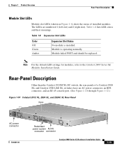
... Expansion Slot LEDs Color Off Green Amber Expansion Slot Status No module is operating normally. Rear-Panel Description Other than the Catalyst 2924M XL DC switch, the rear panels of installed modules. Chapter 1 Product Overview Rear-Panel Description Module Slot LEDs Module slot LEDs (shown ... Figure 1-10 Catalyst 2912 XL, 2924 XL, and 2924C XL Rear Panel Fans 47295 11.000A-/1O2R.75A/AT2I0N50G0-2-8400HV~Z AC power connector +5DVSCPIENPCPO@IUWF9TIAEES,[email protected] CONSOLE Redundant power system RJ-45 connector connector 78-6461-04 Catalyst 2900 Series XL...
... Expansion Slot LEDs Color Off Green Amber Expansion Slot Status No module is operating normally. Rear-Panel Description Other than the Catalyst 2924M XL DC switch, the rear panels of installed modules. Chapter 1 Product Overview Rear-Panel Description Module Slot LEDs Module slot LEDs (shown ... Figure 1-10 Catalyst 2912 XL, 2924 XL, and 2924C XL Rear Panel Fans 47295 11.000A-/1O2R.75A/AT2I0N50G0-2-8400HV~Z AC power connector +5DVSCPIENPCPO@IUWF9TIAEES,[email protected] CONSOLE Redundant power system RJ-45 connector connector 78-6461-04 Catalyst 2900 Series XL...
Hardware Installation Guide
Page 42
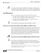
... 600 (model PWR600-AC-RPS)-supports the Catalyst 2912 XL, 2924C XL, 2924 XL, 2924MF XL, and 2924M XL switches. • Cisco RPS 300 (model PWR300-AC-RPS-N1)-supports the Catalyst 2912 LRE XL and 2924 LRE XL switches Note The Cisco RPS does not support the Catalyst 2924M XL DC switch. The switches do not recommend the redundant-with-reboot...
... 600 (model PWR600-AC-RPS)-supports the Catalyst 2912 XL, 2924C XL, 2924 XL, 2924MF XL, and 2924M XL switches. • Cisco RPS 300 (model PWR300-AC-RPS-N1)-supports the Catalyst 2912 LRE XL and 2924 LRE XL switches Note The Cisco RPS does not support the Catalyst 2924M XL DC switch. The switches do not recommend the redundant-with-reboot...
Hardware Installation Guide
Page 54
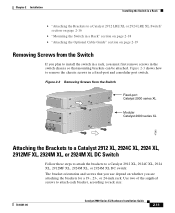
..." rack mount point mount point To install the switch in these procedures: • "Removing Screws from the Switch" section on page 2-11 • "Attaching the Brackets to a Catalyst 2912 XL, 2924C XL, 2924 XL, 2912MF XL, 2924M XL, or 2924M XL DC Switch" section on page 2-11 2-10 Catalyst 2900 Series XL Hardware Installation Guide 78-6461-04...
..." rack mount point mount point To install the switch in these procedures: • "Removing Screws from the Switch" section on page 2-11 • "Attaching the Brackets to a Catalyst 2912 XL, 2924C XL, 2924 XL, 2912MF XL, 2924M XL, or 2924M XL DC Switch" section on page 2-11 2-10 Catalyst 2900 Series XL Hardware Installation Guide 78-6461-04...
Hardware Installation Guide
Page 55
...Removing Screws from the Switch Catalyst 2900 SERIES XL Fixed-port Catalyst 2900 series XL Catalyst 2900 SERIES XL 22X 23X 24X Modular Catalyst 2900 series XL 47292 Attaching the Brackets to a Catalyst 2912 XL, 2924C XL, 2924 XL, 2912MF XL, 2924M XL, or 2924M XL DC Switch Follow these steps to ... screws to attach each bracket, according to a Catalyst 2912 XL, 2924C XL, 2924 XL, 2912MF XL, 2924M XL, or 2924M XL DC switch: The bracket orientation and screws that mounting brackets can be attached. Figure 2-3 Removing Screws from the Switch If you are attaching the brackets for a 19...
...Removing Screws from the Switch Catalyst 2900 SERIES XL Fixed-port Catalyst 2900 series XL Catalyst 2900 SERIES XL 22X 23X 24X Modular Catalyst 2900 series XL 47292 Attaching the Brackets to a Catalyst 2912 XL, 2924C XL, 2924 XL, 2912MF XL, 2924M XL, or 2924M XL DC Switch Follow these steps to ... screws to attach each bracket, according to a Catalyst 2912 XL, 2924C XL, 2924 XL, 2912MF XL, 2924M XL, or 2924M XL DC switch: The bracket orientation and screws that mounting brackets can be attached. Figure 2-3 Removing Screws from the Switch If you are attaching the brackets for a 19...
Hardware Installation Guide
Page 56
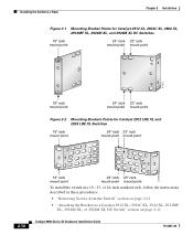
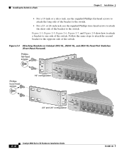
... the supplied Phillips truss-head screws to attach the short side of the bracket to one side of the switch. Figure 2-4 Attaching Brackets on Catalyst 2912 XL, 2924C XL, and 2924 XL Fixed-Port Switches (Front-Panel Forward) Phillips flat-head screws Phillips truss-head screws 19" configuration MODE 1X 2X 3X 4X 5X...
... the supplied Phillips truss-head screws to attach the short side of the bracket to one side of the switch. Figure 2-4 Attaching Brackets on Catalyst 2912 XL, 2924C XL, and 2924 XL Fixed-Port Switches (Front-Panel Forward) Phillips flat-head screws Phillips truss-head screws 19" configuration MODE 1X 2X 3X 4X 5X...
Hardware Installation Guide
Page 58
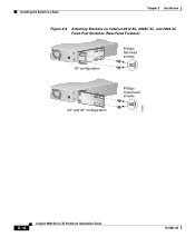
Installing the Switch in a Rack Chapter 2 Installation Figure 2-6 Attaching Brackets on Catalyst 2912 XL, 2924C XL, and 2924 XL Fixed-Port Switches (Rear-Panel Forward) 19" configuration Phillips flat-head screws 23" and 24" configuration Phillips truss-head screws 47298 2-14 Catalyst 2900 Series XL Hardware Installation Guide 78-6461-04
Installing the Switch in a Rack Chapter 2 Installation Figure 2-6 Attaching Brackets on Catalyst 2912 XL, 2924C XL, and 2924 XL Fixed-Port Switches (Rear-Panel Forward) 19" configuration Phillips flat-head screws 23" and 24" configuration Phillips truss-head screws 47298 2-14 Catalyst 2900 Series XL Hardware Installation Guide 78-6461-04
Hardware Installation Guide
Page 101
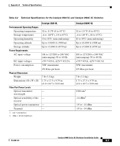
Transmit - 1. Appendix A Technical Specifications Table A-2 Technical Specifications for the Catalyst 2924 XL and Catalyst 2924C XL Switches Catalyst 2924 XL Environmental Operating Ranges Operating temperature 32 to 113°F (0 to 45°C) Storage temperature -4 to 149°F ... (H x W x D) Fiber-Port Power Levels 1.73 x 17.5 x 9.79 in. (4.4 x 44.5 x 24.8 cm) Optical transmitter - receiver Optical power transmitter - dBm = decibel milliwatt Catalyst 2924C XL 32 to 113°F (0 to 45°C) -4 to 149°F (-10 to 65°C) 10 to 85% (noncondensing) Up to 10,000 ft (3000...
Transmit - 1. Appendix A Technical Specifications Table A-2 Technical Specifications for the Catalyst 2924 XL and Catalyst 2924C XL Switches Catalyst 2924 XL Environmental Operating Ranges Operating temperature 32 to 113°F (0 to 45°C) Storage temperature -4 to 149°F ... (H x W x D) Fiber-Port Power Levels 1.73 x 17.5 x 9.79 in. (4.4 x 44.5 x 24.8 cm) Optical transmitter - receiver Optical power transmitter - dBm = decibel milliwatt Catalyst 2924C XL 32 to 113°F (0 to 45°C) -4 to 149°F (-10 to 65°C) 10 to 85% (noncondensing) Up to 10,000 ft (3000...
Hardware Installation Guide
Page 113
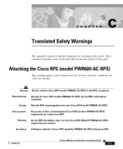
...receptacle. Collegare soltanto il Cisco RPS (modello PWR600-AC-RPS) alla presa RPS. 78-6461-04 Catalyst 2900 Series XL Hardware Installation Guide C-1 Warning Attach only the Cisco RPS (model PWR600-AC-RPS) to the Catalyst 2912 XL, 2924 XL, 2924C XL, 2924M XL, and 2924C XL switches. Warnung: An die ...RPS-Steckhülse darf nur das Cisco RPS (Modell PWR600-AC-...
...receptacle. Collegare soltanto il Cisco RPS (modello PWR600-AC-RPS) alla presa RPS. 78-6461-04 Catalyst 2900 Series XL Hardware Installation Guide C-1 Warning Attach only the Cisco RPS (model PWR600-AC-RPS) to the Catalyst 2912 XL, 2924 XL, 2924C XL, 2924M XL, and 2924C XL switches. Warnung: An die ...RPS-Steckhülse darf nur das Cisco RPS (Modell PWR600-AC-...