
Hardware Installation Guide
Page 7
... a Wall 2-22 Powering On the Switch and Running POST 2-24 Connecting to DC Power 2-25 Preparing for Installation 2-25 Grounding the Switch 2-26 Wiring the DC-Input Power Source 2-29 Connecting to a 10/100 Port 2-35 Connecting to a 100BASE-FX Port 2-37 Connecting to an LRE Port 2-38 Connecting to a Module Port 2-42 Connecting to the Console...
... a Wall 2-22 Powering On the Switch and Running POST 2-24 Connecting to DC Power 2-25 Preparing for Installation 2-25 Grounding the Switch 2-26 Wiring the DC-Input Power Source 2-29 Connecting to a 10/100 Port 2-35 Connecting to a 100BASE-FX Port 2-37 Connecting to an LRE Port 2-38 Connecting to a Module Port 2-42 Connecting to the Console...
Hardware Installation Guide
Page 22
..., and asynchronous transfer mode (ATM) modules • On the Catalyst 2924M XL DC switch, a direct current (DC) power converter • On the Catalyst 2912 LRE XL and 2924 LRE XL switches, up to 24 LRE ports through one RJ-21 connector and hot swapping capability with the Cisco LRE customer premises equipment (CPE) devices • Supports up to...
..., and asynchronous transfer mode (ATM) modules • On the Catalyst 2924M XL DC switch, a direct current (DC) power converter • On the Catalyst 2912 LRE XL and 2924 LRE XL switches, up to 24 LRE ports through one RJ-21 connector and hot swapping capability with the Cisco LRE customer premises equipment (CPE) devices • Supports up to...
Hardware Installation Guide
Page 23
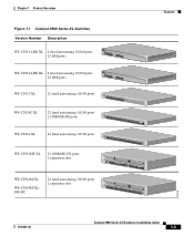
... 1 Product Overview Figure 1-1 Catalyst 2900 Series XL Switches Version Number Description WS-C2912-LRE-XL 4 fixed autosensing 10/100 ports INPUT OUTPUT PWR PWR RESET TEMP FAN 9X 10X 11X 12X 12 LRE ports Cisco RPS 300 WS-C2924-LRE-XL 4 fixed autosensing 10/100 ports 24 LRE ports INPUT OUTPUT PWR PWR RESET TEMP... FAN 9X 10X 11X 12X Cisco RPS 300 WS-C2912-XL 12 fixed autosensing 10/100 ports MODE 1X 2X 3X 4X 5X 6X 7X 8X 9X 10X 10BaseT/100BASE-TX 11X 12X Catalyst 2900 SERIES XL WS-C2924C...
... 1 Product Overview Figure 1-1 Catalyst 2900 Series XL Switches Version Number Description WS-C2912-LRE-XL 4 fixed autosensing 10/100 ports INPUT OUTPUT PWR PWR RESET TEMP FAN 9X 10X 11X 12X 12 LRE ports Cisco RPS 300 WS-C2924-LRE-XL 4 fixed autosensing 10/100 ports 24 LRE ports INPUT OUTPUT PWR PWR RESET TEMP... FAN 9X 10X 11X 12X Cisco RPS 300 WS-C2912-XL 12 fixed autosensing 10/100 ports MODE 1X 2X 3X 4X 5X 6X 7X 8X 9X 10X 10BaseT/100BASE-TX 11X 12X Catalyst 2900 SERIES XL WS-C2924C...
Hardware Installation Guide
Page 27
... system telephone network 78-6461-04 Catalyst 2900 Series XL Hardware Installation Guide 1-7 If telephone services, such as voice or integrated services digital network (ISDN), use the same cabling as LRE traffic, the LRE port must be connected to the patch panel through a private branch exchange (PBX) switch, a Cisco LRE 48 POTS Splitter can...
... system telephone network 78-6461-04 Catalyst 2900 Series XL Hardware Installation Guide 1-7 If telephone services, such as voice or integrated services digital network (ISDN), use the same cabling as LRE traffic, the LRE port must be connected to the patch panel through a private branch exchange (PBX) switch, a Cisco LRE 48 POTS Splitter can...
Hardware Installation Guide
Page 32
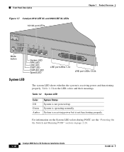
...Figure 1-7 Catalyst 2912 LRE XL and 2924 LRE XL LEDs 10/100 port LEDs Chapter 1 Product Overview SYSTEM RPS MODE LRE STAT DUPLX SPEED Mode button 1X 2X 3X 4X System LED RPS LED LRE LED STAT LED DUPLEX LED Speed LED LRE port LEDs 1-12 LRE port LEDs 13-24 48002 ...is receiving power and functioning properly. For information on the System LED colors during POST, see the "Powering On the Switch and Running POST" section on page 2-24. 1-12 Catalyst 2900 Series XL Hardware Installation Guide 78-6461-04 Table 1-2 System LED Color Off Green Amber System Status System is ...
...Figure 1-7 Catalyst 2912 LRE XL and 2924 LRE XL LEDs 10/100 port LEDs Chapter 1 Product Overview SYSTEM RPS MODE LRE STAT DUPLX SPEED Mode button 1X 2X 3X 4X System LED RPS LED LRE LED STAT LED DUPLEX LED Speed LED LRE port LEDs 1-12 LRE port LEDs 13-24 48002 ...is receiving power and functioning properly. For information on the System LED colors during POST, see the "Powering On the Switch and Running POST" section on page 2-24. 1-12 Catalyst 2900 Series XL Hardware Installation Guide 78-6461-04 Table 1-2 System LED Color Off Green Amber System Status System is ...
Hardware Installation Guide
Page 38
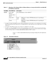
... displayed by the right-most LEDs. Green LRE port or remote CPE Ethernet port is operating at 100 Mbps. 1. The LEDs on Catalyst 2900 LRE XL switches with Cisco IOS Release 12.0(5.x)WC1 or Cisco IOS Release 12.0(5.x)WC2 provide information about any connected...24%+ 25 - 49%+ 50%+ Catalyst 2900 SERIES XL 1-18 Catalyst 2900 Series XL Hardware Installation Guide 78-6461-04 Front-Panel Description Chapter 1 Product Overview Table 1-7 Meanings of Port Status LEDs for Different Modes on Catalyst 2912 LRE XL and 2924 LRE XL Switches (continued) Port Mode SPEED Port LED Color Cisco...
... displayed by the right-most LEDs. Green LRE port or remote CPE Ethernet port is operating at 100 Mbps. 1. The LEDs on Catalyst 2900 LRE XL switches with Cisco IOS Release 12.0(5.x)WC1 or Cisco IOS Release 12.0(5.x)WC2 provide information about any connected...24%+ 25 - 49%+ 50%+ Catalyst 2900 SERIES XL 1-18 Catalyst 2900 Series XL Hardware Installation Guide 78-6461-04 Front-Panel Description Chapter 1 Product Overview Table 1-7 Meanings of Port Status LEDs for Different Modes on Catalyst 2912 LRE XL and 2924 LRE XL Switches (continued) Port Mode SPEED Port LED Color Cisco...
Hardware Installation Guide
Page 50
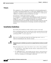
... Hungarian EMC Class A requirements (MSZEN55022). Catalyst 2900 Series XL Hardware Installation Guide 2-6 78-6461-04 Follow the procedures in a rack, or on page 2-24. Installation Guidelines The switch can be installed on a table or shelf, in the "Powering On the Switch and Running POST" section on a wall...should be sure to observe these guidelines: • For 10/100 ports, cable lengths from the switch to connected devices are up to 328 feet (100 meters). • For 100BASE-FX ports, cable lengths from the switch to connected devices are up to 1351 feet (412 meters) for half...
... Hungarian EMC Class A requirements (MSZEN55022). Catalyst 2900 Series XL Hardware Installation Guide 2-6 78-6461-04 Follow the procedures in a rack, or on page 2-24. Installation Guidelines The switch can be installed on a table or shelf, in the "Powering On the Switch and Running POST" section on a wall...should be sure to observe these guidelines: • For 10/100 ports, cable lengths from the switch to connected devices are up to 328 feet (100 meters). • For 100BASE-FX ports, cable lengths from the switch to connected devices are up to 1351 feet (412 meters) for half...
Hardware Installation Guide
Page 55
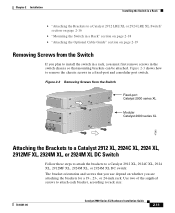
... from the Switch Catalyst 2900 SERIES XL Fixed-port Catalyst 2900 series XL Catalyst 2900 SERIES XL 22X 23X 24X Modular Catalyst 2900 series XL 47292 Attaching the Brackets to a Catalyst 2912 XL, 2924C XL, 2924 XL, 2912MF XL, 2924M XL, or 2924M XL DC Switch Follow these ...Switch in a Rack" section on page 2-18 • "Attaching the Optional Cable Guide" section on whether you must first remove screws in a fixed-port and a modular port switch. Figure 2-3 Removing Screws from the Switch If you plan to install the switch in a rack, you are attaching the brackets for a 19-, 23-, or 24...
... from the Switch Catalyst 2900 SERIES XL Fixed-port Catalyst 2900 series XL Catalyst 2900 SERIES XL 22X 23X 24X Modular Catalyst 2900 series XL 47292 Attaching the Brackets to a Catalyst 2912 XL, 2924C XL, 2924 XL, 2912MF XL, 2924M XL, or 2924M XL DC Switch Follow these ...Switch in a Rack" section on page 2-18 • "Attaching the Optional Cable Guide" section on whether you must first remove screws in a fixed-port and a modular port switch. Figure 2-3 Removing Screws from the Switch If you plan to install the switch in a rack, you are attaching the brackets for a 19-, 23-, or 24...
Hardware Installation Guide
Page 56
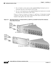
... or a telco rack, use the supplied Phillips truss-head screws to attach the short side of the switch. Figure 2-4 Attaching Brackets on Catalyst 2912 XL, 2924C XL, and 2924 XL Fixed-Port Switches (Front-Panel Forward) Phillips flat-head screws Phillips truss-head screws 19" configuration MODE 1X 2X 3X ...4X 5X 6X 7X 47738 23" and 24" configuration MODE 1X 2X 3X 4X 5X 6X 7X 2-12 Catalyst 2900 Series XL Hardware Installation Guide 78...
... or a telco rack, use the supplied Phillips truss-head screws to attach the short side of the switch. Figure 2-4 Attaching Brackets on Catalyst 2912 XL, 2924C XL, and 2924 XL Fixed-Port Switches (Front-Panel Forward) Phillips flat-head screws Phillips truss-head screws 19" configuration MODE 1X 2X 3X ...4X 5X 6X 7X 47738 23" and 24" configuration MODE 1X 2X 3X 4X 5X 6X 7X 2-12 Catalyst 2900 Series XL Hardware Installation Guide 78...
Hardware Installation Guide
Page 58
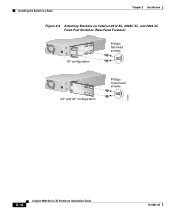
Installing the Switch in a Rack Chapter 2 Installation Figure 2-6 Attaching Brackets on Catalyst 2912 XL, 2924C XL, and 2924 XL Fixed-Port Switches (Rear-Panel Forward) 19" configuration Phillips flat-head screws 23" and 24" configuration Phillips truss-head screws 47298 2-14 Catalyst 2900 Series XL Hardware Installation Guide 78-6461-04
Installing the Switch in a Rack Chapter 2 Installation Figure 2-6 Attaching Brackets on Catalyst 2912 XL, 2924C XL, and 2924 XL Fixed-Port Switches (Rear-Panel Forward) 19" configuration Phillips flat-head screws 23" and 24" configuration Phillips truss-head screws 47298 2-14 Catalyst 2900 Series XL Hardware Installation Guide 78-6461-04
Hardware Installation Guide
Page 68
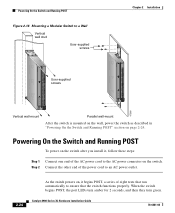
... POST, a series of the AC power cord to ensure that the switch functions properly. Catalyst 2900 Series XL Hardware Installation Guide 78-6461-04 Step 2 Connect the other end of the power cord to an AC power outlet. 2-24 As the switch powers on, it , follow these steps: Step 1 Connect one end... of eight tests that run automatically to the AC power connector on the switch. When the switch begins POST, the port LEDs turn amber for 2 seconds, and then they turn...
... POST, a series of the AC power cord to ensure that the switch functions properly. Catalyst 2900 Series XL Hardware Installation Guide 78-6461-04 Step 2 Connect the other end of the power cord to an AC power outlet. 2-24 As the switch powers on, it , follow these steps: Step 1 Connect one end... of eight tests that run automatically to the AC power connector on the switch. When the switch begins POST, the port LEDs turn amber for 2 seconds, and then they turn...
Hardware Installation Guide
Page 82
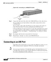
... be turned on when both Cisco 575 LRE CPE and Cisco 585 LRE CPE devices to the 100BASE-FX port of the cable to your LRE switch, and you can hot swap the CPE devices without powering down the switch or disrupting the other switch ports. 2-38 Catalyst 2900 Series XL Hardware Installation... Guide 78-6461-04 This takes about 30 seconds, and then the port LED turns green. Connecting to an LRE Port Depending on the switch model, you can connect the LRE port to either 12 or 24 LRE ...
... be turned on when both Cisco 575 LRE CPE and Cisco 585 LRE CPE devices to the 100BASE-FX port of the cable to your LRE switch, and you can hot swap the CPE devices without powering down the switch or disrupting the other switch ports. 2-38 Catalyst 2900 Series XL Hardware Installation... Guide 78-6461-04 This takes about 30 seconds, and then the port LED turns green. Connecting to an LRE Port Depending on the switch model, you can connect the LRE port to either 12 or 24 LRE ...
Hardware Installation Guide
Page 101
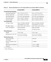
... @9A, +12V @0.5A 70W (maximum) 239 Btus per hour 7 lb (3.2 kg) 1.73 x 17.5 x 9.79 in. (4.4 x 44.5 x 24.8 cm) 1300 nm1 -14 dBm2 -19 to -14 dBm -19 to 60 Hz +5V @9A, +12V @0.5A Power consumption 70W (maximum) Physical Dimensions...7 lb (3.2 kg) Dimensions (H x W x D) Fiber-Port Power Levels 1.73 x 17.5 x 9.79 in. (4.4 x 44.5 x 24.8 cm) Optical transmitter - nm = nanometers 2. Appendix A Technical Specifications Table A-2 Technical Specifications for the Catalyst 2924 XL and Catalyst 2924C XL Switches Catalyst 2924 XL Environmental Operating Ranges Operating temperature 32 to 113°F...
... @9A, +12V @0.5A 70W (maximum) 239 Btus per hour 7 lb (3.2 kg) 1.73 x 17.5 x 9.79 in. (4.4 x 44.5 x 24.8 cm) 1300 nm1 -14 dBm2 -19 to -14 dBm -19 to 60 Hz +5V @9A, +12V @0.5A Power consumption 70W (maximum) Physical Dimensions...7 lb (3.2 kg) Dimensions (H x W x D) Fiber-Port Power Levels 1.73 x 17.5 x 9.79 in. (4.4 x 44.5 x 24.8 cm) Optical transmitter - nm = nanometers 2. Appendix A Technical Specifications Table A-2 Technical Specifications for the Catalyst 2924 XL and Catalyst 2924C XL Switches Catalyst 2924 XL Environmental Operating Ranges Operating temperature 32 to 113°F...
Hardware Installation Guide
Page 109
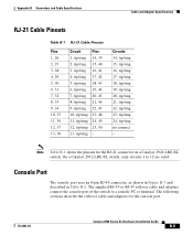
..., tip/ring 23, tip/ring 24, tip/ring no connect - The following sections describe the rollover cable and adapters for the RJ-21 connector on a Catalyst 2924 LRE XL switch. The supplied RJ-45-to-RJ-45 rollover cable and adapters connect the console port of the switch to 12 are valid. Appendix B... 9, tip/ring 22, 47 10, tip/ring 23, 48 11, tip/ring 24, 49 12, tip/ring 25, 50 13, tip/ring - Console Port The console port uses an 8-pin RJ-45 connector, as shown in Figure B-7 and described in Table B-2. On a Catalyst 2912 LRE XL switch, only circuits 1 to a console PC or terminal.
..., tip/ring 23, tip/ring 24, tip/ring no connect - The following sections describe the rollover cable and adapters for the RJ-21 connector on a Catalyst 2924 LRE XL switch. The supplied RJ-45-to-RJ-45 rollover cable and adapters connect the console port of the switch to 12 are valid. Appendix B... 9, tip/ring 22, 47 10, tip/ring 23, 48 11, tip/ring 24, 49 12, tip/ring 25, 50 13, tip/ring - Console Port The console port uses an 8-pin RJ-45 connector, as shown in Figure B-7 and described in Table B-2. On a Catalyst 2912 LRE XL switch, only circuits 1 to a console PC or terminal.
Hardware Installation Guide
Page 159
...11, 2-15, 2-22 N no on/off switch warning C-24 O overtemperature warning C-9 P PC, connecting to switch 2-42 performance problems, solving 3-3 personnel warning C-3 pinouts 10/100BASE-T ports B-2 cable, straight-through and crossover B-4 RJ-21... connector B-5 RJ-45-to-DB-25 terminal adapter B-8 RJ-45-to-DB-9 terminal adapter B-7 rollover cable B-7, B-8 Index port LEDs Catalyst 2900 LRE XL 1-17 ports...
...11, 2-15, 2-22 N no on/off switch warning C-24 O overtemperature warning C-9 P PC, connecting to switch 2-42 performance problems, solving 3-3 personnel warning C-3 pinouts 10/100BASE-T ports B-2 cable, straight-through and crossover B-4 RJ-21... connector B-5 RJ-45-to-DB-25 terminal adapter B-8 RJ-45-to-DB-9 terminal adapter B-7 rollover cable B-7, B-8 Index port LEDs Catalyst 2900 LRE XL 1-17 ports...

Hardware Installation Guide
Page 160
...port B-5 RPS connector 1-21 regulatory statements, EMC 2-4 to 2-6 RJ-21 connector illustration 1-7 pinouts B-5 RJ-45 connector, console port 2-43, B-3, B-5 RJ-45 console port 1-19 rollover cable 2-43, B-6 identifying B-6 pinouts B-8 RPS 300 connector 1-23 supported switches... 1-22 warning C-2 RPS 600 connector 1-22 LED 1-13 supported switches...SunNet Manager 1-4 supply circuit warning C-15 switch powering on 2-24 switched ports, module 1-8 System LED 1-12 T ...
...port B-5 RPS connector 1-21 regulatory statements, EMC 2-4 to 2-6 RJ-21 connector illustration 1-7 pinouts B-5 RJ-45 connector, console port 2-43, B-3, B-5 RJ-45 console port 1-19 rollover cable 2-43, B-6 identifying B-6 pinouts B-8 RPS 300 connector 1-23 supported switches... 1-22 warning C-2 RPS 600 connector 1-22 LED 1-13 supported switches...SunNet Manager 1-4 supply circuit warning C-15 switch powering on 2-24 switched ports, module 1-8 System LED 1-12 T ...


