Hardware Installation Guide
Page 9
.../Off Switch Warning C-24 Chassis Warning-Rack-Mounting and Servicing C-25 Reinforced Insulation Warning C-29 LAN Connections Only Warning C-30 No Field-Replaceable Units Warning C-31 Installation Warning C-32 SELV Source Warning C-33 Restricted Access Warning C-34 Shielded Ethernet Cables Warning... C-35 Grounded Equipment Warning C-36 Ground Connection Warning C-37 Qualified Personnel Warning C-38 DC Power Disconnection Warning C-39 Exposed Wire Lead Warning C-41 Contents 78-6461-04 Catalyst 2900 Series XL Hardware Installation ...
.../Off Switch Warning C-24 Chassis Warning-Rack-Mounting and Servicing C-25 Reinforced Insulation Warning C-29 LAN Connections Only Warning C-30 No Field-Replaceable Units Warning C-31 Installation Warning C-32 SELV Source Warning C-33 Restricted Access Warning C-34 Shielded Ethernet Cables Warning... C-35 Grounded Equipment Warning C-36 Ground Connection Warning C-37 Qualified Personnel Warning C-38 DC Power Disconnection Warning C-39 Exposed Wire Lead Warning C-41 Contents 78-6461-04 Catalyst 2900 Series XL Hardware Installation ...
Hardware Installation Guide
Page 11
... are familiar with the concepts and terminology of Ethernet and local area networking. Organization This guide is for the networking or computer technician responsible for installing a switch in a rack, on a desk, or on a wall. It describes the physical and performance characteristics of Catalyst 2900 series XL switches. Chapter 2, "Installation," provides the procedures for installing...
... are familiar with the concepts and terminology of Ethernet and local area networking. Organization This guide is for the networking or computer technician responsible for installing a switch in a rack, on a desk, or on a wall. It describes the physical and performance characteristics of Catalyst 2900 series XL switches. Chapter 2, "Installation," provides the procedures for installing...
Hardware Installation Guide
Page 21
... from other switches. The Catalyst 2900 XL switches have these topics that allows an Ethernet network to reach distances up to which you can be deployed as the switches. • Switch features, including management options • Descriptions of the front and rear panels • Descriptions of the LEDs Features The switches are stackable 10/100 Ethernet switches to 4921...
... from other switches. The Catalyst 2900 XL switches have these topics that allows an Ethernet network to reach distances up to which you can be deployed as the switches. • Switch features, including management options • Descriptions of the front and rear panels • Descriptions of the LEDs Features The switches are stackable 10/100 Ethernet switches to 4921...
Hardware Installation Guide
Page 22
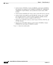
...-TX, 1000BASE-X, 1000BASE-T, Gigabit Ethernet, and asynchronous transfer mode (ATM) modules • On the Catalyst 2924M XL DC switch, a direct current (DC) power converter • On the Catalyst 2912 LRE XL and 2924 LRE XL switches, up to 24 LRE ports through one RJ-21 connector and hot swapping capability with the Cisco LRE customer premises equipment...
...-TX, 1000BASE-X, 1000BASE-T, Gigabit Ethernet, and asynchronous transfer mode (ATM) modules • On the Catalyst 2924M XL DC switch, a direct current (DC) power converter • On the Catalyst 2912 LRE XL and 2924 LRE XL switches, up to 24 LRE ports through one RJ-21 connector and hot swapping capability with the Cisco LRE customer premises equipment...

Hardware Installation Guide
Page 24
... an SNMP-compatible management station that can be launched from anywhere in your management station directly to the switch console port or by using Telnet from the CLI. Catalyst 2900 Series XL Hardware Installation Guide 1-4 78-6461-04 Front-Panel Description Chapter 1 Product Overview Management... HP OpenView or SunNet Manager. For more information about CMS, the CLI, and SNMP refer to twenty-four Long-Reach Ethernet ports (See Figure 1-4). The switch supports a comprehensive set of MIB extensions and four Remote Monitoring (RMON) groups. You can access the CLI either by ...
... an SNMP-compatible management station that can be launched from anywhere in your management station directly to the switch console port or by using Telnet from the CLI. Catalyst 2900 Series XL Hardware Installation Guide 1-4 78-6461-04 Front-Panel Description Chapter 1 Product Overview Management... HP OpenView or SunNet Manager. For more information about CMS, the CLI, and SNMP refer to twenty-four Long-Reach Ethernet ports (See Figure 1-4). The switch supports a comprehensive set of MIB extensions and four Remote Monitoring (RMON) groups. You can access the CLI either by ...
Hardware Installation Guide
Page 27
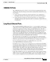
... the same Catalyst 2900 LRE XL switch, and you can be connected to LRE ports on the attached device are connected through a basic telephone service, also known as existing telephone lines. or 62.5/125-micron multimode fiber-optic cabling. Long-Reach Ethernet Ports The Long-Reach Ethernet (LRE) ports...as voice or integrated services digital network (ISDN), use 50/125- You can connect Cisco 575 LRE CPE and Cisco 585 LRE CPE devices to the patch panel through a private branch exchange (PBX) switch, a Cisco LRE 48 POTS Splitter can hot swap the CPE devices without powering down the...
... the same Catalyst 2900 LRE XL switch, and you can be connected to LRE ports on the attached device are connected through a basic telephone service, also known as existing telephone lines. or 62.5/125-micron multimode fiber-optic cabling. Long-Reach Ethernet Ports The Long-Reach Ethernet (LRE) ports...as voice or integrated services digital network (ISDN), use 50/125- You can connect Cisco 575 LRE CPE and Cisco 585 LRE CPE devices to the patch panel through a private branch exchange (PBX) switch, a Cisco LRE 48 POTS Splitter can hot swap the CPE devices without powering down the...

Hardware Installation Guide
Page 28
... Catalyst 2900 Series XL Hardware Installation Guide 1-8 78-6461-04 For more information about the Cisco LRE 48 POTS Splitter (PS-1M-LRE-48), refer to a telephone network is not required, a splitter is managed through the switch management interfaces. Note Cisco Long-Reach Ethernet ...(LRE) products are for the Cisco LRE 48 POTS Splitter. Digital telephones connected to digital PBX switches that use the 0 to share lines with analog, Integrated Services...
... Catalyst 2900 Series XL Hardware Installation Guide 1-8 78-6461-04 For more information about the Cisco LRE 48 POTS Splitter (PS-1M-LRE-48), refer to a telephone network is not required, a splitter is managed through the switch management interfaces. Note Cisco Long-Reach Ethernet ...(LRE) products are for the Cisco LRE 48 POTS Splitter. Digital telephones connected to digital PBX switches that use the 0 to share lines with analog, Integrated Services...
Hardware Installation Guide
Page 29
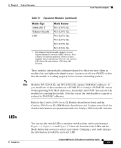
...release required, refer to monitor switch activity and its performance. If you insert them in a 2924M XL or Catalyst 2912MF XL switch (both supporting 8192 MAC addresses), the module fails POST. Refer to the Catalyst 2900 Series XL Modules Installation Guide and the Catalyst 2900 Series XL ATM Modules ...XL WS-X2972-XL WS-X2951-XL WS-X2961-XL 1. The Ethernet Gigabit module supports several Gigabit Interface Converter (GBIC) devices. A power-on expansion modules for the Catalyst 2900 Series XL and Catalyst 3500 Series XL Switches. LEDs 78-6461-04 You can start the module by each ...
...release required, refer to monitor switch activity and its performance. If you insert them in a 2924M XL or Catalyst 2912MF XL switch (both supporting 8192 MAC addresses), the module fails POST. Refer to the Catalyst 2900 Series XL Modules Installation Guide and the Catalyst 2900 Series XL ATM Modules ...XL WS-X2972-XL WS-X2951-XL WS-X2961-XL 1. The Ethernet Gigabit module supports several Gigabit Interface Converter (GBIC) devices. A power-on expansion modules for the Catalyst 2900 Series XL and Catalyst 3500 Series XL Switches. LEDs 78-6461-04 You can start the module by each ...

Hardware Installation Guide
Page 35
... mode on all Catalyst 2900 XL and Catalyst 3500 XL switches except the Catalyst 2912 LRE XL and Catalyst 2924 LRE XL switches. Ethernet link status of the LRE ports on the Catalyst 2912 LRE XL and Catalyst 2924 LRE XL switches. The default setting is active, the 10/100 switch ports on the Catalyst 2912 LRE XL and Catalyst 2924 LRE XL...
... mode on all Catalyst 2900 XL and Catalyst 3500 XL switches except the Catalyst 2912 LRE XL and Catalyst 2924 LRE XL switches. Ethernet link status of the LRE ports on the Catalyst 2912 LRE XL and Catalyst 2924 LRE XL switches. The default setting is active, the 10/100 switch ports on the Catalyst 2912 LRE XL and Catalyst 2924 LRE XL...

Hardware Installation Guide
Page 37
... of Port Status LEDs for LED information about the 10/100 ports. Port is operating in STP forwarding state. Cisco IOS Release 12.0(5.x)WC42 3 Cyan (off) Cyan (off) LRE port or remote CPE Ethernet port is in half-duplex mode. Green LRE link present on the LRE port. Cyan (off ) No LRE.... Green LRE link present on the LRE port. Cyan (off ) No LRE link present on the LRE CPE unable to reflect Ethernet link status. See Table 1-5 for Different Modes on Catalyst 2912 LRE XL and 2924 LRE XL Switches Port Mode Port LED Color Description LRE Note In LRE mode, the 10/100...
... of Port Status LEDs for LED information about the 10/100 ports. Port is operating in STP forwarding state. Cisco IOS Release 12.0(5.x)WC42 3 Cyan (off) Cyan (off) LRE port or remote CPE Ethernet port is in half-duplex mode. Green LRE link present on the LRE port. Cyan (off ) No LRE.... Green LRE link present on the LRE port. Cyan (off ) No LRE link present on the LRE CPE unable to reflect Ethernet link status. See Table 1-5 for Different Modes on Catalyst 2912 LRE XL and 2924 LRE XL Switches Port Mode Port LED Color Description LRE Note In LRE mode, the 10/100...
Hardware Installation Guide
Page 38
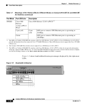
... CPE Ethernet link status from a switch with Cisco IOS Release 12.0(5.x)WC1 or Cisco IOS Release 12.0(5.x)WC2 provide information about any connected LRE CPE devices. Figure 1-9 shows bandwidth utilization percentages displayed by the right-most LEDs. The LEDs on Catalyst 2900 LRE XL switches with Cisco IOS ... for Different Modes on Catalyst 2912 LRE XL and 2924 LRE XL Switches (continued) Port Mode SPEED Port LED Color Cisco IOS Release 12.0(5.x)WC1/ WC21 Description Cisco IOS Release 12.0(5.x)WC42 3 Cyan (off) Cyan (off) LRE port or remote CPE Ethernet port is operating at 10...
... CPE Ethernet link status from a switch with Cisco IOS Release 12.0(5.x)WC1 or Cisco IOS Release 12.0(5.x)WC2 provide information about any connected LRE CPE devices. Figure 1-9 shows bandwidth utilization percentages displayed by the right-most LEDs. The LEDs on Catalyst 2900 LRE XL switches with Cisco IOS ... for Different Modes on Catalyst 2912 LRE XL and 2924 LRE XL Switches (continued) Port Mode SPEED Port LED Color Cisco IOS Release 12.0(5.x)WC1/ WC21 Description Cisco IOS Release 12.0(5.x)WC42 3 Cyan (off) Cyan (off) LRE port or remote CPE Ethernet port is operating at 10...

Hardware Installation Guide
Page 51
... Clearance to the shipping container and save them. If any item is missing or damaged, contact your Cisco representative or reseller for support. Your Catalyst 2900 XL switch is shipped with these conditions: - Front-panel indicators can be greater than normal room temperature. Note If... ports is sufficient for unrestricted cabling. - Chapter 2 Installation Preparing for Installation • For Long-Reach Ethernet (LRE) ports, cable lengths from the switch to the connected Ethernet device are up to 4921 feet (1500 meters). • Cabling is away from the shipping container, and...
... Clearance to the shipping container and save them. If any item is missing or damaged, contact your Cisco representative or reseller for support. Your Catalyst 2900 XL switch is shipped with these conditions: - Front-panel indicators can be greater than normal room temperature. Note If... ports is sufficient for unrestricted cabling. - Chapter 2 Installation Preparing for Installation • For Long-Reach Ethernet (LRE) ports, cable lengths from the switch to the connected Ethernet device are up to 4921 feet (1500 meters). • Cabling is away from the shipping container, and...
Hardware Installation Guide
Page 79
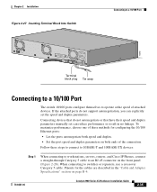
... performance, choose one of these steps to connect to 10BASE-T and 100BASE-TX devices: Step 1 When connecting to workstations, servers, routers, and Cisco IP Phones, connect a straight-through Category 5 cable to operate at the speed of the connection. When connecting to a 10/100 Port 74080 ... plug Tie wrap Connecting to a 10/100 Port The switch 10/100 ports configure themselves to an RJ-45 connector on page B-4. 78-6461-04 Catalyst 2900 Series XL Hardware Installation Guide 2-35 Pinouts for configuring the 10/100 Ethernet ports: • Let the ports autonegotiate both speed and...
... performance, choose one of these steps to connect to 10BASE-T and 100BASE-TX devices: Step 1 When connecting to workstations, servers, routers, and Cisco IP Phones, connect a straight-through Category 5 cable to operate at the speed of the connection. When connecting to a 10/100 Port 74080 ... plug Tie wrap Connecting to a 10/100 Port The switch 10/100 ports configure themselves to an RJ-45 connector on page B-4. 78-6461-04 Catalyst 2900 Series XL Hardware Installation Guide 2-35 Pinouts for configuring the 10/100 Ethernet ports: • Let the ports autonegotiate both speed and...
Hardware Installation Guide
Page 90
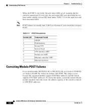
...addresses. After the restart, the address capacity of the switch is operational. Note POST failures are usually fatal. Catalyst 2900 Series XL Hardware Installation Guide 3-2 78-6461-04 Call Cisco Systems if your switch does not pass POST. If a test fails, the...POST Descriptions Switch LED 1 2 3 4 5 6 7 8 Component Tested DRAM Flash memory Switch CPU System board CPU interface ASIC Switch core ASIC Ethernet controller ASIC Ethernet interfaces Correcting Module POST Failures If you install modules WS-X2914-XL or WS-X2922-XL in a Catalyst 2924M XL or Catalyst 2912MF XL switch, the...
...addresses. After the restart, the address capacity of the switch is operational. Note POST failures are usually fatal. Catalyst 2900 Series XL Hardware Installation Guide 3-2 78-6461-04 Call Cisco Systems if your switch does not pass POST. If a test fails, the...POST Descriptions Switch LED 1 2 3 4 5 6 7 8 Component Tested DRAM Flash memory Switch CPU System board CPU interface ASIC Switch core ASIC Ethernet controller ASIC Ethernet interfaces Correcting Module POST Failures If you install modules WS-X2914-XL or WS-X2922-XL in a Catalyst 2924M XL or Catalyst 2912MF XL switch, the...

Hardware Installation Guide
Page 105
Figure B-1 shows the pinouts. 78-6461-04 Catalyst 2900 Series XL Hardware Installation Guide B-1 These ports have their transmit (TD) and receive (RD) signals internally crossed so that you use standard RJ-45 connectors and Ethernet pinouts with internal crossovers, as shown by an X in the ...port name. Connector Specifications 10/100 Ports The 10/100 Ethernet ports use to connect the switch to the port. APPENDIX B Connectors and Cable Specifications This appendix describes the Catalyst 2900 XL switch ports and the cables and adapters that a straight-through cable and an ...
Figure B-1 shows the pinouts. 78-6461-04 Catalyst 2900 Series XL Hardware Installation Guide B-1 These ports have their transmit (TD) and receive (RD) signals internally crossed so that you use standard RJ-45 connectors and Ethernet pinouts with internal crossovers, as shown by an X in the ...port name. Connector Specifications 10/100 Ports The 10/100 Ethernet ports use to connect the switch to the port. APPENDIX B Connectors and Cable Specifications This appendix describes the Catalyst 2900 XL switch ports and the cables and adapters that a straight-through cable and an ...


