Hardware Installation Guide
Page 2
... and Voice LAN are registered trademarks of Cisco Systems, Inc.; and Aironet, ASIST, BPX, Catalyst, CCDA, CCDP, CCIE, CCNA, CCNP, Cisco, the Cisco Certified Internetwork Expert logo, Cisco IOS, the Cisco IOS logo, Cisco Press, Cisco Systems, Cisco Systems Capital, the Cisco Systems logo, Empowering the Internet Generation, ... or radio. (That is no longer complying with the specifications in a residential installation. This equipment generates, uses, and can determine whether your authority to Increase Your Internet Quotient, and iQuick Study are designed to provide reasonable...
... and Voice LAN are registered trademarks of Cisco Systems, Inc.; and Aironet, ASIST, BPX, Catalyst, CCDA, CCDP, CCIE, CCNA, CCNP, Cisco, the Cisco Certified Internetwork Expert logo, Cisco IOS, the Cisco IOS logo, Cisco Press, Cisco Systems, Cisco Systems Capital, the Cisco Systems logo, Empowering the Internet Generation, ... or radio. (That is no longer complying with the specifications in a residential installation. This equipment generates, uses, and can determine whether your authority to Increase Your Internet Quotient, and iQuick Study are designed to provide reasonable...

Hardware Installation Guide
Page 3
The use of the word partner does not imply a partnership relationship between Cisco and any other trademarks mentioned in this document or Web site are the property of their respective owners. All rights reserved. All other company. (0201R) Catalyst 2900 Series XL Hardware Installation Guide Copyright © 1999-2002, Cisco Systems, Inc.
The use of the word partner does not imply a partnership relationship between Cisco and any other trademarks mentioned in this document or Web site are the property of their respective owners. All rights reserved. All other company. (0201R) Catalyst 2900 Series XL Hardware Installation Guide Copyright © 1999-2002, Cisco Systems, Inc.
Hardware Installation Guide
Page 5
... Documentation Feedback xviii Obtaining Technical Assistance xviii Cisco.com xviii Technical Assistance Center xix Contacting TAC by Using the Cisco TAC Website xix Contacting TAC by Telephone xx Product Overview 1-1 Features 1-1 Management Interface Options 1-4 Front-Panel Description 1-4 10/100 Ports 1-6 100BASE-FX Ports 1-7 Long-Reach Ethernet Ports 1-7 Catalyst 2900 Series XL Hardware Installation Guide v
... Documentation Feedback xviii Obtaining Technical Assistance xviii Cisco.com xviii Technical Assistance Center xix Contacting TAC by Using the Cisco TAC Website xix Contacting TAC by Telephone xx Product Overview 1-1 Features 1-1 Management Interface Options 1-4 Front-Panel Description 1-4 10/100 Ports 1-6 100BASE-FX Ports 1-7 Long-Reach Ethernet Ports 1-7 Catalyst 2900 Series XL Hardware Installation Guide v
Hardware Installation Guide
Page 12
...following conventions and symbols: Note Means reader take note. Notes contain helpful suggestions or references to the switch. Caution Means reader be used to connect to materials not contained in this guide. In this situation, you might do something ...Catalyst 2900 Series XL Hardware Installation Guide xii 78-6461-04 Examples use these conventions: • Terminal sessions and system displays are in screen font. • Information you enter is in boldface screen font. • Nonprinting characters, such as passwords or tabs, are in boldface. • Arguments for the switches...
...following conventions and symbols: Note Means reader take note. Notes contain helpful suggestions or references to the switch. Caution Means reader be used to connect to materials not contained in this guide. In this situation, you might do something ...Catalyst 2900 Series XL Hardware Installation Guide xii 78-6461-04 Examples use these conventions: • Terminal sessions and system displays are in screen font. • Information you enter is in boldface screen font. • Nonprinting characters, such as passwords or tabs, are in boldface. • Arguments for the switches...
Hardware Installation Guide
Page 18
...partners can obtain documentation, troubleshooting tips, and sample configurations from anywhere in the toolbar to the Cisco documentation group. For Cisco.com registered users, additional troubleshooting tools are using the product-specific CD and you display the document listing for your comments by mail, for...open access to bug-doc@cisco.com. Otherwise, you wish to send your comments by completing the online survey. Click Submit to comment on the World Wide Web, you can find information about Cisco and our networking solutions, xviii Catalyst 2900 Series XL Hardware ...
...partners can obtain documentation, troubleshooting tips, and sample configurations from anywhere in the toolbar to the Cisco documentation group. For Cisco.com registered users, additional troubleshooting tools are using the product-specific CD and you display the document listing for your comments by mail, for...open access to bug-doc@cisco.com. Otherwise, you wish to send your comments by completing the online survey. Click Submit to comment on the World Wide Web, you can find information about Cisco and our networking solutions, xviii Catalyst 2900 Series XL Hardware ...
Hardware Installation Guide
Page 19
..., contact TAC by a maintenance contract. Contacting TAC by Using the Cisco TAC Website If you can self-register on the status of the above cases, use the Cisco TAC website to quickly find answers to the following website: http://www.cisco.com/register/ 78-6461-04 Catalyst 2900 Series XL Hardware Installation Guide xix Customers and...
..., contact TAC by a maintenance contract. Contacting TAC by Using the Cisco TAC Website If you can self-register on the status of the above cases, use the Cisco TAC website to quickly find answers to the following website: http://www.cisco.com/register/ 78-6461-04 Catalyst 2900 Series XL Hardware Installation Guide xix Customers and...
Hardware Installation Guide
Page 20
...service is not restored quickly. Obtaining Technical Assistance Preface If you cannot resolve your technical issue by using the TAC Case Open tool at the following website: http://www.cisco.com/warp/public/687/Directory/DirTAC.shtml P1 and P2 level problems are defined as follows: ...a priority level 1 (P1) or priority level 2 (P2) problem, contact TAC by using the TAC online resources, Cisco.com registered users can open a case online by telephone and immediately open a case. Catalyst 2900 Series XL Hardware Installation Guide xx 78-6461-04 To obtain a directory of your business...
...service is not restored quickly. Obtaining Technical Assistance Preface If you cannot resolve your technical issue by using the TAC Case Open tool at the following website: http://www.cisco.com/warp/public/687/Directory/DirTAC.shtml P1 and P2 level problems are defined as follows: ...a priority level 1 (P1) or priority level 2 (P2) problem, contact TAC by using the TAC online resources, Cisco.com registered users can open a case online by telephone and immediately open a case. Catalyst 2900 Series XL Hardware Installation Guide xx 78-6461-04 To obtain a directory of your business...

Hardware Installation Guide
Page 24
...Manager. Front-Panel Description Chapter 1 Product Overview Management Interface Options You can configure and monitor individual switches and switch clusters by using these front-panel components. Catalyst 2900 Series XL Hardware Installation Guide 1-4 78-6461-04 For more information about CMS, the CLI... twenty-four Long-Reach Ethernet ports (See Figure 1-4). Using CMS, you can also display network topologies to gather link information and to display switch images to the Catalyst 2900 Series XL and Catalyst 3500 Series XL Software Configuration Guide. You can fully configure...
...Manager. Front-Panel Description Chapter 1 Product Overview Management Interface Options You can configure and monitor individual switches and switch clusters by using these front-panel components. Catalyst 2900 Series XL Hardware Installation Guide 1-4 78-6461-04 For more information about CMS, the CLI... twenty-four Long-Reach Ethernet ports (See Figure 1-4). Using CMS, you can also display network topologies to gather link information and to display switch images to the Catalyst 2900 Series XL and Catalyst 3500 Series XL Software Configuration Guide. You can fully configure...
Hardware Installation Guide
Page 26
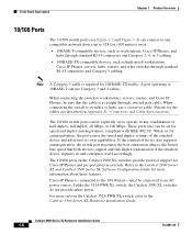
... of the attached device and advertises its own capabilities. When connecting the switch to workstations, servers, routers, and Cisco IP Phones, be connected to switches or hubs, use Category 3 and 4 cables. These ports also can use a crossover cable. Refer to 328 feet (100 meters) away: &#...duplex autonegotiation, compliant with IEEE 802.3U. Unlike the 3524-PWR XL switch, the Catalyst 2900 XL switches do not provide inline power. If the connected device also supports autonegotiation, the switch port negotiates the best connection (that both devices support and full-duplex ...
... of the attached device and advertises its own capabilities. When connecting the switch to workstations, servers, routers, and Cisco IP Phones, be connected to switches or hubs, use Category 3 and 4 cables. These ports also can use a crossover cable. Refer to 328 feet (100 meters) away: &#...duplex autonegotiation, compliant with IEEE 802.3U. Unlike the 3524-PWR XL switch, the Catalyst 2900 XL switches do not provide inline power. If the connected device also supports autonegotiation, the switch port negotiates the best connection (that both devices support and full-duplex ...
Hardware Installation Guide
Page 27
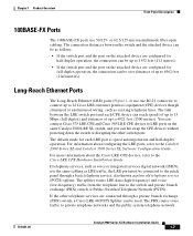
...-frequency) traffic from the telephone line to the Catalyst 2900 Series XL and Catalyst 3500 Series XL Software Configuration Guide. The link between the switch and the attached device can be as voice or integrated services digital network (ISDN), use 50/125- For information about the Cisco LRE CPE devices, refer to private telephone networks...
...-frequency) traffic from the telephone line to the Catalyst 2900 Series XL and Catalyst 3500 Series XL Software Configuration Guide. The link between the switch and the attached device can be as voice or integrated services digital network (ISDN), use 50/125- For information about the Cisco LRE CPE devices, refer to private telephone networks...

Hardware Installation Guide
Page 28
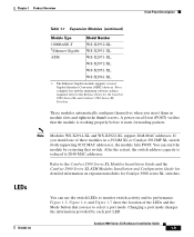
... Splitter (PS-1M-LRE-48), refer to 700 kHz frequency range. Note Cisco Long-Reach Ethernet (LRE) products are for the Cisco LRE 48 POTS Splitter. Digital telephones connected to digital PBX switches that use frequencies above 700 kHz. [CSCdu73260] If the installation does not have a PBX... the patch panel. Due to the proprietary nature of digital PBX switches, some digital PBX switch services use the 0 to the Installation Notes for the Catalyst 2900 XL hot-swappable modules. Table 1-1 lists the modules that use frequencies above 700 kHz do not work when sharing a line with ...
... Splitter (PS-1M-LRE-48), refer to 700 kHz frequency range. Note Cisco Long-Reach Ethernet (LRE) products are for the Cisco LRE 48 POTS Splitter. Digital telephones connected to digital PBX switches that use frequencies above 700 kHz. [CSCdu73260] If the installation does not have a PBX... the patch panel. Due to the proprietary nature of digital PBX switches, some digital PBX switch services use the 0 to the Installation Notes for the Catalyst 2900 XL hot-swappable modules. Table 1-1 lists the modules that use frequencies above 700 kHz do not work when sharing a line with ...
Hardware Installation Guide
Page 29
...-XL support 2048 MAC addresses. Refer to monitor switch activity and its performance. If you use the switch LEDs to the Catalyst 2900 Series XL Modules Installation Guide and the Catalyst 2900 Series XL ATM Modules Installation and Configuration Guide for Catalyst 2900 series XL switches. Catalyst 2900 Series XL Hardware Installation Guide 1-9 Chapter 1...-X2971-XL WS-X2972-XL WS-X2951-XL WS-X2961-XL 1. These modules automatically configure themselves when you insert them in a 2924M XL or Catalyst 2912MF XL switch (both supporting 8192 MAC addresses), the module fails POST.
...-XL support 2048 MAC addresses. Refer to monitor switch activity and its performance. If you use the switch LEDs to the Catalyst 2900 Series XL Modules Installation Guide and the Catalyst 2900 Series XL ATM Modules Installation and Configuration Guide for Catalyst 2900 series XL switches. Catalyst 2900 Series XL Hardware Installation Guide 1-9 Chapter 1...-X2971-XL WS-X2972-XL WS-X2951-XL WS-X2961-XL 1. These modules automatically configure themselves when you insert them in a 2924M XL or Catalyst 2912MF XL switch (both supporting 8192 MAC addresses), the module fails POST.

Hardware Installation Guide
Page 30
... Series XL Software Configuration Guide describes how to use CMS to manage standalone or individual switches and how to use cluster management software to manage switch clusters]. Figure 1-5 Catalyst 2912 XL, 2924 XL, and 2924C XL LEDs 10/100 port LEDs System LED Port mode LEDs MODE 1X 2X 3X 4X 5X ...6X 7X Mode RPS button LED 47288 1-10 Catalyst 2900 Series XL ...
... Series XL Software Configuration Guide describes how to use CMS to manage standalone or individual switches and how to use cluster management software to manage switch clusters]. Figure 1-5 Catalyst 2912 XL, 2924 XL, and 2924C XL LEDs 10/100 port LEDs System LED Port mode LEDs MODE 1X 2X 3X 4X 5X ...6X 7X Mode RPS button LED 47288 1-10 Catalyst 2900 Series XL ...
Hardware Installation Guide
Page 33
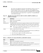
... it restarts. RPS is connected but is not installed. Pressing the Mode button on the Catalyst 2912 XL, 2924C XL, 2924 XL, 2924MF XL, 2924M XL, and 2924M XL DC Switches Color Off Green Blinking green Amber RPS Status RPS is connected but not functioning. •...device (redundancy has been allocated to the appropriate switch documentation for redundant power system (RPS) descriptions specific for the switch. Chapter 1 Product Overview Front-Panel Description RPS LED The Catalyst 2912 LRE XL and Catalyst 2924 LRE XL switches use the Cisco RPS 600 (model PWR600-AC-RPS). The RPS...
... it restarts. RPS is connected but is not installed. Pressing the Mode button on the Catalyst 2912 XL, 2924C XL, 2924 XL, 2924MF XL, 2924M XL, and 2924M XL DC Switches Color Off Green Blinking green Amber RPS Status RPS is connected but not functioning. •...device (redundancy has been allocated to the appropriate switch documentation for redundant power system (RPS) descriptions specific for the switch. Chapter 1 Product Overview Front-Panel Description RPS LED The Catalyst 2912 LRE XL and Catalyst 2924 LRE XL switches use the Cisco RPS 600 (model PWR600-AC-RPS). The RPS...

Hardware Installation Guide
Page 34
...-Panel Description Chapter 1 Product Overview Table 1-3 RPS LED on the Catalyst 2912 LRE XL and 2924 LRE XL Switches (continued) Color Solid amber Blinking amber RPS Status The RPS is in standby mode or in use by the switch. (See Figure 1-8.) The port duplex mode: full duplex or half...LED. Contact Cisco Systems. The internal power supply in a switch has failed, and the RPS is providing power to the switch (redundancy has been allocated to this device). Press the Standby/Active button on the Catalyst 2912 XL, 2924C XL, 2924 XL, 2924MF XL, 2924M XL, and 2924M XL DC Switches Mode LED...
...-Panel Description Chapter 1 Product Overview Table 1-3 RPS LED on the Catalyst 2912 LRE XL and 2924 LRE XL Switches (continued) Color Solid amber Blinking amber RPS Status The RPS is in standby mode or in use by the switch. (See Figure 1-8.) The port duplex mode: full duplex or half...LED. Contact Cisco Systems. The internal power supply in a switch has failed, and the RPS is providing power to the switch (redundancy has been allocated to this device). Press the Standby/Active button on the Catalyst 2912 XL, 2924C XL, 2924 XL, 2924MF XL, 2924M XL, and 2924M XL DC Switches Mode LED...

Hardware Installation Guide
Page 36
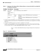
Activity. Error frames can remain amber for Different Modes on Catalyst 2912 XL, 2924C XL, 2924 XL, 2924MF XL, 2924M XL, and 2924M XL DC Switches Port Mode STAT (port status) Port LED Color Off Solid green Flashing green Alternating green-amber Solid amber UTL Green (utilization) FDUP (port ...for up to the left of the right-most LED is amber, the switch is using 50 percent or more of its total capacity, and so on a logarithmic scale. Port is operating at 100 Mbps. 1-16 Catalyst 2900 Series XL Hardware Installation Guide 78-6461-04 The LEDs display backplane utilization...
Activity. Error frames can remain amber for Different Modes on Catalyst 2912 XL, 2924C XL, 2924 XL, 2924MF XL, 2924M XL, and 2924M XL DC Switches Port Mode STAT (port status) Port LED Color Off Solid green Flashing green Alternating green-amber Solid amber UTL Green (utilization) FDUP (port ...for up to the left of the right-most LED is amber, the switch is using 50 percent or more of its total capacity, and so on a logarithmic scale. Port is operating at 100 Mbps. 1-16 Catalyst 2900 Series XL Hardware Installation Guide 78-6461-04 The LEDs display backplane utilization...
Hardware Installation Guide
Page 38
...Guide 78-6461-04 Figure 1-9 shows bandwidth utilization percentages displayed by the right-most LEDs. The LEDs on Catalyst 2900 LRE XL switches with Cisco IOS Release 12.0(5.x)WC1 or Cisco IOS Release 12.0(5.x)WC2 provide information about any connected LRE CPE devices. Front-Panel Description Chapter 1 Product ...LED Color Cisco IOS Release 12.0(5.x)WC1/ WC21 Description Cisco IOS Release 12.0(5.x)WC42 3 Cyan (off) Cyan (off) LRE port or remote CPE Ethernet port is operating at 10 Mbps. To verify the LRE CPE Ethernet link status from a switch with this release or higher, use the ...
...Guide 78-6461-04 Figure 1-9 shows bandwidth utilization percentages displayed by the right-most LEDs. The LEDs on Catalyst 2900 LRE XL switches with Cisco IOS Release 12.0(5.x)WC1 or Cisco IOS Release 12.0(5.x)WC2 provide information about any connected LRE CPE devices. Front-Panel Description Chapter 1 Product ...LED Color Cisco IOS Release 12.0(5.x)WC1/ WC21 Description Cisco IOS Release 12.0(5.x)WC42 3 Cyan (off) Cyan (off) LRE port or remote CPE Ethernet port is operating at 10 Mbps. To verify the LRE CPE Ethernet link status from a switch with this release or higher, use the ...
Hardware Installation Guide
Page 41
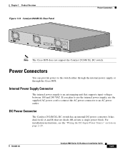
...The internal power supply is an autoranging unit that are diode-OR-ed into a single power block. B +- Note The Cisco RPS does not support the Catalyst 2924M XL DC switch. If you plan to use the internal power supply, use the supplied AC power cord to connect the AC power connector to the... switch either through the internal power supply or through the Cisco RPS. It has dual feeds (A and B) that supports input voltages...
...The internal power supply is an autoranging unit that are diode-OR-ed into a single power block. B +- Note The Cisco RPS does not support the Catalyst 2924M XL DC switch. If you plan to use the internal power supply, use the supplied AC power cord to connect the AC power connector to the... switch either through the internal power supply or through the Cisco RPS. It has dual feeds (A and B) that supports input voltages...
Hardware Installation Guide
Page 42
... 2924C XL, 2924 XL, 2924MF XL, and 2924M XL switches. • Cisco RPS 300 (model PWR300-AC-RPS-N1)-supports the Catalyst 2912 LRE XL and 2924 LRE XL switches Note The Cisco RPS does not support the Catalyst 2924M XL DC switch. The AC input to the Cisco RPS is fully redundant, but the DC output... or might be damaged. Power Connectors Chapter 1 Product Overview Caution You must connect the Catalyst 2924M XL DC switch only to a DC-input power source that use up to the four DC output power modules. Use a one-to-one cable (one DC output power module for four external devices that ...
... 2924C XL, 2924 XL, 2924MF XL, and 2924M XL switches. • Cisco RPS 300 (model PWR300-AC-RPS-N1)-supports the Catalyst 2912 LRE XL and 2924 LRE XL switches Note The Cisco RPS does not support the Catalyst 2924M XL DC switch. The AC input to the Cisco RPS is fully redundant, but the DC output... or might be damaged. Power Connectors Chapter 1 Product Overview Caution You must connect the Catalyst 2924M XL DC switch only to a DC-input power source that use up to the four DC output power modules. Use a one-to-one cable (one DC output power module for four external devices that ...
Hardware Installation Guide
Page 43
... any subsequent switch is not supported by using the supplied rollover cable and DB-9 adapter. When the device internal power supply has been brought up or replaced, the RPS automatically stops powering the device. Chapter 1 Product Overview Power Connectors RPS Connector on the Catalyst 2912 LRE ...and 2924 LRE XL Switches The RPS is a 300W redundant power system that can order a kit (part number ACS-DSBUASYN=) containing that adapter from Cisco. Warning Attach only the Cisco RPS (model PWR300-AC-RPS-N1) to a ...
... any subsequent switch is not supported by using the supplied rollover cable and DB-9 adapter. When the device internal power supply has been brought up or replaced, the RPS automatically stops powering the device. Chapter 1 Product Overview Power Connectors RPS Connector on the Catalyst 2912 LRE ...and 2924 LRE XL Switches The RPS is a 300W redundant power system that can order a kit (part number ACS-DSBUASYN=) containing that adapter from Cisco. Warning Attach only the Cisco RPS (model PWR300-AC-RPS-N1) to a ...

