
Installation Guide
Page 2
...• Plug the equipment into an outlet that event, your authority to use the equipment may be limited by Cisco Systems, Inc. ALL STATEMENTS, INFORMATION, AND RECOMMENDATIONS IN THIS MANUAL ARE BELIEVED TO BE ACCURATE BUT ARE PRESENTED WITHOUT WARRANTY OF ANY KIND, EXPRESS OR IMPLIED. Modifying the equipment ...DAMAGES, INCLUDING, WITHOUT LIMITATION, LOST PROFITS OR LOSS OR DAMAGE TO DATA ARISING OUT OF THE USE OR INABILITY TO USE THIS MANUAL, EVEN IF CISCO OR ITS SUPPLIERS HAVE BEEN ADVISED OF THE POSSIBILITY OF SUCH DAMAGES. IF YOU ARE UNABLE TO LOCATE THE SOFTWARE LICENSE OR LIMITED ...
...• Plug the equipment into an outlet that event, your authority to use the equipment may be limited by Cisco Systems, Inc. ALL STATEMENTS, INFORMATION, AND RECOMMENDATIONS IN THIS MANUAL ARE BELIEVED TO BE ACCURATE BUT ARE PRESENTED WITHOUT WARRANTY OF ANY KIND, EXPRESS OR IMPLIED. Modifying the equipment ...DAMAGES, INCLUDING, WITHOUT LIMITATION, LOST PROFITS OR LOSS OR DAMAGE TO DATA ARISING OUT OF THE USE OR INABILITY TO USE THIS MANUAL, EVEN IF CISCO OR ITS SUPPLIERS HAVE BEEN ADVISED OF THE POSSIBILITY OF SUCH DAMAGES. IF YOU ARE UNABLE TO LOCATE THE SOFTWARE LICENSE OR LIMITED ...

Installation Guide
Page 13
... de waarschuwing die bij het apparaat wordt geleverd, wilt raadplegen. Before you might do something that accompanied this manual. Warning IMPORTANT SAFETY INSTRUCTIONS This warning symbol means danger. BEWAAR DEZE INSTRUCTIES 78-6456-04 Catalyst 3500 Series XL Hardware Installation Guide xiii In this situation, you work on any equipment, be aware...
... de waarschuwing die bij het apparaat wordt geleverd, wilt raadplegen. Before you might do something that accompanied this manual. Warning IMPORTANT SAFETY INSTRUCTIONS This warning symbol means danger. BEWAAR DEZE INSTRUCTIES 78-6456-04 Catalyst 3500 Series XL Hardware Installation Guide xiii In this situation, you work on any equipment, be aware...

Installation Guide
Page 45
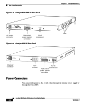
... 1 Product Overview Rear-Panel Description Rear-Panel Description Switch rear panels have an AC power connector, an RPS connector, and an RJ-45 console port (see Figure 1-17, Figure 1-19, Figure 1-18, and Figure 1-20), which are described in this section. Figure 1-17 Catalyst 3508G XL Rear Panel 18963 RATING 100-127... RATING 100-127/200-240V~ 1.0A/0.5A 50-60HZ AC power connector 78-6456-04 CONSOLE DC INPUTS FOR REMOTE POWER SUPPLY SPECIFIED IN MANUAL. +5V @24A, +12V @.5A RJ-45 console port Redundant power system connector Fans Catalyst 3500 Series XL Hardware Installation Guide 1-21
... 1 Product Overview Rear-Panel Description Rear-Panel Description Switch rear panels have an AC power connector, an RPS connector, and an RJ-45 console port (see Figure 1-17, Figure 1-19, Figure 1-18, and Figure 1-20), which are described in this section. Figure 1-17 Catalyst 3508G XL Rear Panel 18963 RATING 100-127... RATING 100-127/200-240V~ 1.0A/0.5A 50-60HZ AC power connector 78-6456-04 CONSOLE DC INPUTS FOR REMOTE POWER SUPPLY SPECIFIED IN MANUAL. +5V @24A, +12V @.5A RJ-45 console port Redundant power system connector Fans Catalyst 3500 Series XL Hardware Installation Guide 1-21
Installation Guide
Page 46
...200-240V~ 3.5A/1.8A 50-60HZ DC INPUTS FOR REMOTE POWER SUPPLY SPECIFIED IN MANUAL. -48V @3A, +12V @6A CONSOLE AC power connector Redundant power system connector RJ-45 console port Figure 1-20 Catalyst 3548 XL Rear Panel Chapter 1 Product Overview Fans 30293 28012 RATING 100-127/...POWER SUPPLY SPECIFIED IN MANUAL +3.3V @17A, +12 @1.1A CONSOLE AC power connector Fan exhaust RJ-45 console port Redundant power system connector Power Connectors You can provide power to the switch either through the internal power supply or through the Cisco RPS. 1-22 Catalyst 3500 Series XL Hardware...
...200-240V~ 3.5A/1.8A 50-60HZ DC INPUTS FOR REMOTE POWER SUPPLY SPECIFIED IN MANUAL. -48V @3A, +12V @6A CONSOLE AC power connector Redundant power system connector RJ-45 console port Figure 1-20 Catalyst 3548 XL Rear Panel Chapter 1 Product Overview Fans 30293 28012 RATING 100-127/...POWER SUPPLY SPECIFIED IN MANUAL +3.3V @17A, +12 @1.1A CONSOLE AC power connector Fan exhaust RJ-45 console port Redundant power system connector Power Connectors You can provide power to the switch either through the internal power supply or through the Cisco RPS. 1-22 Catalyst 3500 Series XL Hardware...

Installation Guide
Page 63
...to the RPS receptacle. Statement 257 78-6456-04 Catalyst 3500 Series XL Hardware Installation Guide 2-5 regulatory information for Installation The following warning applies to the Catalyst 3524-PWR XL switch: Warning Attach only the Cisco RPS (model PWR300-AC-RPS-N1) to take ...appropriate countermeasures. Chapter 2 Installing and Starting Up the Switch Preparing for this product is a Class A Information Product...
...to the RPS receptacle. Statement 257 78-6456-04 Catalyst 3500 Series XL Hardware Installation Guide 2-5 regulatory information for Installation The following warning applies to the Catalyst 3524-PWR XL switch: Warning Attach only the Cisco RPS (model PWR300-AC-RPS-N1) to take ...appropriate countermeasures. Chapter 2 Installing and Starting Up the Switch Preparing for this product is a Class A Information Product...
Installation Guide
Page 76
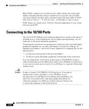
...; Let the ports autonegotiate both speed and duplex. • Set the port speed and duplex parameters on the Catalyst 3524-PWR XL switch to either automatically provide inline power when a Cisco IP Phone is connected. You can explicitly set can result in no linkage. Caution It takes... Chapter 2 Installing and Starting Up the Switch When POST completes successfully, the port LEDs return to operate at the speed of attached devices. If POST fails, refer to Chapter 3, "Troubleshooting," to that have their speed and duplex parameters manually set the speed and duplex parameters.
...; Let the ports autonegotiate both speed and duplex. • Set the port speed and duplex parameters on the Catalyst 3524-PWR XL switch to either automatically provide inline power when a Cisco IP Phone is connected. You can explicitly set can result in no linkage. Caution It takes... Chapter 2 Installing and Starting Up the Switch When POST completes successfully, the port LEDs return to operate at the speed of attached devices. If POST fails, refer to Chapter 3, "Troubleshooting," to that have their speed and duplex parameters manually set the speed and duplex parameters.

Installation Guide
Page 82
...the "Identifying a Rollover Cable" section on page B-5 for a description of the supplied rollover cable in the switch • Using a BOOTP server This section describes each method. 2-24 Catalyst 3500 Series XL Hardware Installation Guide 78-6456-04 Boot the terminal-emulation program if you are using a PC... SPECIFIED IN MANUAL. +5V @24A, +12V @1.0A RJ-45 Console port Step 4 Step 5 Step 6 Rollover cable Attach the supplied RJ-45-to-DB-9 female DTE adapter to a PC or attach an appropriate adapter to the terminal. Assigning Switch Information You can assign the switch IP address ...
...the "Identifying a Rollover Cable" section on page B-5 for a description of the supplied rollover cable in the switch • Using a BOOTP server This section describes each method. 2-24 Catalyst 3500 Series XL Hardware Installation Guide 78-6456-04 Boot the terminal-emulation program if you are using a PC... SPECIFIED IN MANUAL. +5V @24A, +12V @1.0A RJ-45 Console port Step 4 Step 5 Step 6 Rollover cable Attach the supplied RJ-45-to-DB-9 female DTE adapter to a PC or attach an appropriate adapter to the terminal. Assigning Switch Information You can assign the switch IP address ...

