
Installation Guide
Page 6
... 1-14 RPS LED 1-15 Port LEDs and Modes 1-16 Rear-Panel Description 1-21 Power Connectors 1-22 Internal Power Supply Connector 1-23 Cisco RPS Connector 1-23 Console Port 1-24 Management Options 1-24 Network Configuration Examples 1-25 Design Concepts for Installation 2-2 Warnings 2-2 EMC Regulatory ... 2-6 Hungary 2-7 Installation Guidelines 2-7 Verifying Package Contents 2-8 Catalyst 3500 Series XL Hardware Installation Guide vi 78-6456-03 to Medium-Sized Network Configuration 1-29 Collapsed Backbone and Switch Cluster Configuration 1-31 Large Campus Configuration 1-33 Installing and ...
... 1-14 RPS LED 1-15 Port LEDs and Modes 1-16 Rear-Panel Description 1-21 Power Connectors 1-22 Internal Power Supply Connector 1-23 Cisco RPS Connector 1-23 Console Port 1-24 Management Options 1-24 Network Configuration Examples 1-25 Design Concepts for Installation 2-2 Warnings 2-2 EMC Regulatory ... 2-6 Hungary 2-7 Installation Guidelines 2-7 Verifying Package Contents 2-8 Catalyst 3500 Series XL Hardware Installation Guide vi 78-6456-03 to Medium-Sized Network Configuration 1-29 Collapsed Backbone and Switch Cluster Configuration 1-31 Large Campus Configuration 1-33 Installing and ...
Installation Guide
Page 7
...Rack 2-13 Attaching the Optional Cable Guide 2-13 Installing the Switch on a Wall 2-15 Attaching the Brackets to the Switch 2-15 Attaching the Switch to a Wall 2-16 Installing the Switch on a Table or Shelf 2-17 Powering On the Switch and Running POST 2-17 Connecting to the 10/100 Ports... 1000BaseX GBIC Module Port 2-21 Connecting to a GigaStack GBIC Module Port 2-22 Connecting a PC or Terminal to the Console Port 2-23 Assigning Switch Information 2-24 Using the Setup Program 2-25 Using BOOTP 2-29 Default Configuration Settings 2-29 Where to Go Next 2-31 Troubleshooting 3-1 Understanding POST ...
...Rack 2-13 Attaching the Optional Cable Guide 2-13 Installing the Switch on a Wall 2-15 Attaching the Brackets to the Switch 2-15 Attaching the Switch to a Wall 2-16 Installing the Switch on a Table or Shelf 2-17 Powering On the Switch and Running POST 2-17 Connecting to the 10/100 Ports... 1000BaseX GBIC Module Port 2-21 Connecting to a GigaStack GBIC Module Port 2-22 Connecting a PC or Terminal to the Console Port 2-23 Assigning Switch Information 2-24 Using the Setup Program 2-25 Using BOOTP 2-29 Default Configuration Settings 2-29 Where to Go Next 2-31 Troubleshooting 3-1 Understanding POST ...

Installation Guide
Page 9
INDEX Grounded Equipment Warning C-23 Supply Circuit Warning C-24 No On/Off Switch Warning C-25 Power Supply Warning C-27 Work During Lightning Activity Warning C-30 Product Disposal Warning C-31 Chassis Warning-Rack-Mounting and Servicing C-33 Chassis Power Connection Warning C-38 Shock Hazard from Interconnections Warning C-41 Contents 78-6456-03 Catalyst 3500 Series XL Hardware Installation Guide ix
INDEX Grounded Equipment Warning C-23 Supply Circuit Warning C-24 No On/Off Switch Warning C-25 Power Supply Warning C-27 Work During Lightning Activity Warning C-30 Product Disposal Warning C-31 Chassis Warning-Rack-Mounting and Servicing C-33 Chassis Power Connection Warning C-38 Shock Hazard from Interconnections Warning C-41 Contents 78-6456-03 Catalyst 3500 Series XL Hardware Installation Guide ix

Installation Guide
Page 11
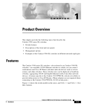
... guide is for the networking or computer technician responsible for installing and configuring a Catalyst 3500 series XL switch. Purpose The Catalyst 3500 Series XL Hardware Installation Guide documents the hardware features of the switches in the series, explains how to install a switch and set up its initial configuration, provides troubleshooting information, and describes how to...
... guide is for the networking or computer technician responsible for installing and configuring a Catalyst 3500 series XL switch. Purpose The Catalyst 3500 Series XL Hardware Installation Guide documents the hardware features of the switches in the series, explains how to install a switch and set up its initial configuration, provides troubleshooting information, and describes how to...

Installation Guide
Page 12
...Connector and Cable Specifications," describes the connectors, cables, and adapters that might arise when you are installing the switch. Catalyst 3500 Series XL Hardware Installation Guide xii 78-6456-04 Organization Preface Organization This guide is organized into the ...Appendix A, "Technical Specifications," lists the physical and environmental specifications for installing a switch on a rack, wall, table, or shelf. It describes the switch ports, the standards they support, and the switch LEDs. Examples use these conventions: • Terminal sessions and system displays are ...
...Connector and Cable Specifications," describes the connectors, cables, and adapters that might arise when you are installing the switch. Catalyst 3500 Series XL Hardware Installation Guide xii 78-6456-04 Organization Preface Organization This guide is organized into the ...Appendix A, "Technical Specifications," lists the physical and environmental specifications for installing a switch on a rack, wall, table, or shelf. It describes the switch ports, the standards they support, and the switch LEDs. Examples use these conventions: • Terminal sessions and system displays are ...
Installation Guide
Page 18
... Publications Preface Related Publications For more information about Catalyst 3500 series XL switches and related products, refer to the following publications: • Quick Start: Catalyst 3500 Series XL Cabling and Setup • Cisco IOS Desktop Switching Software Configuration Guide • Cisco IOS Desktop Switching Command Reference (online only) • Cisco Cluster Management Suite online help also provides detailed...
... Publications Preface Related Publications For more information about Catalyst 3500 series XL switches and related products, refer to the following publications: • Quick Start: Catalyst 3500 Series XL Cabling and Setup • Cisco IOS Desktop Switching Software Configuration Guide • Cisco IOS Desktop Switching Command Reference (online only) • Cisco Cluster Management Suite online help also provides detailed...
Installation Guide
Page 25
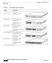
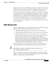
... 10/100 and Gigabit Ethernet traffic from other switches. A feature specific to the Catalyst 3524-PWR XL switch is its ability to provide inline power to Cisco IP Phones. (Phone adapters are stackable 10/100 Ethernet switches to the Catalyst 3524-PWR XL 10/100 switch ports.) Figure 1-1 shows the switch models in the series, and Table 1-1 and...
... 10/100 and Gigabit Ethernet traffic from other switches. A feature specific to the Catalyst 3524-PWR XL switch is its ability to provide inline power to Cisco IP Phones. (Phone adapters are stackable 10/100 Ethernet switches to the Catalyst 3524-PWR XL 10/100 switch ports.) Figure 1-1 shows the switch models in the series, and Table 1-1 and...
Installation Guide
Page 26
... 38 39 40 41 42 43 44 45 46 47 48 STATUS UTIL 47X 1 DUPLEX SPEED 2X MODE 16X 18X 32X 34X 2 48X 30210 Catalyst 3500 Series XL Hardware Installation Guide 1-2 78-6456-04 Features Chapter 1 Product Overview Figure 1-1 Catalyst 3500 Series XL Switches Switch Description WS-C3508G-XL 8 GBIC1-based gigabit module slots 1 SYSTEM... GBIC-based gigabit module slots WS-C3524-PWR-XL 24 autosensing 10/100 inline-power Ethernet ports 2 GBIC-based gigabit module slots WS-C3548-XL 48 autosensing 10/100 Ethernet ports 2 GBIC-based gigabit module slots 1.
... 38 39 40 41 42 43 44 45 46 47 48 STATUS UTIL 47X 1 DUPLEX SPEED 2X MODE 16X 18X 32X 34X 2 48X 30210 Catalyst 3500 Series XL Hardware Installation Guide 1-2 78-6456-04 Features Chapter 1 Product Overview Figure 1-1 Catalyst 3500 Series XL Switches Switch Description WS-C3508G-XL 8 GBIC1-based gigabit module slots 1 SYSTEM... GBIC-based gigabit module slots WS-C3524-PWR-XL 24 autosensing 10/100 inline-power Ethernet ports 2 GBIC-based gigabit module slots WS-C3548-XL 48 autosensing 10/100 Ethernet ports 2 GBIC-based gigabit module slots 1.
Installation Guide
Page 27
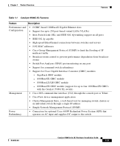
... multicast traffic • Broadcast storm control to prevent performance degradation from broadcast storms • Switch Port Analyzer (SPAN) port monitoring on AC input and supplies DC output to four 1000BaseZX GBICs with the Catalyst 3508G XL switch) Management • Cisco IOS command-line interface (CLI) through the console port or Telnet • CiscoView device...
... multicast traffic • Broadcast storm control to prevent performance degradation from broadcast storms • Switch Port Analyzer (SPAN) port monitoring on AC input and supplies DC output to four 1000BaseZX GBICs with the Catalyst 3508G XL switch) Management • Cisco IOS command-line interface (CLI) through the console port or Telnet • CiscoView device...
Installation Guide
Page 28
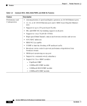
Features Chapter 1 Product Overview Table 1-2 Catalyst 3512, 3524, 3524-PWR, and 3548 XL Features Feature Performance and Configuration Description • Autonegotiation of speed and duplex operation on 10/100 Ethernet ports • 12, 24, or 48 10/100 Ethernet ports and 2 GBIC-... broadcast storms • SPAN port monitoring on any port • Support for command switch redundancy • Support for Cisco GBIC modules - GigaStack GBIC - 1000BaseSX GBIC module - 1000BaseLX/LH GBIC module - 1000BaseZX GBIC module Catalyst 3500 Series XL Hardware Installation Guide 1-4 78-6456-04
Features Chapter 1 Product Overview Table 1-2 Catalyst 3512, 3524, 3524-PWR, and 3548 XL Features Feature Performance and Configuration Description • Autonegotiation of speed and duplex operation on 10/100 Ethernet ports • 12, 24, or 48 10/100 Ethernet ports and 2 GBIC-... broadcast storms • SPAN port monitoring on any port • Support for command switch redundancy • Support for Cisco GBIC modules - GigaStack GBIC - 1000BaseSX GBIC module - 1000BaseLX/LH GBIC module - 1000BaseZX GBIC module Catalyst 3500 Series XL Hardware Installation Guide 1-4 78-6456-04

Installation Guide
Page 29
... supplies DC output to the Catalyst 3512, 3524, and 3548 XL switches • Connection for optional Cisco RPS 300 that you press.) These front-panel components are described in this section. 78-6456-04 Catalyst 3500 Series XL Hardware Installation Guide 1-5 All Catalyst 3500 XL switches have a set of LEDs ... a Mode label that operates on AC input and supplies DC output to the Catalyst 3524-PWR XL switch Inline Power (Catalyst 3524-PWR XL switch only) • Ability to provide inline power for Cisco IP Phones from all 24 10/100 Ethernet ports • Auto-detection and control of inline...
... supplies DC output to the Catalyst 3512, 3524, and 3548 XL switches • Connection for optional Cisco RPS 300 that you press.) These front-panel components are described in this section. 78-6456-04 Catalyst 3500 Series XL Hardware Installation Guide 1-5 All Catalyst 3500 XL switches have a set of LEDs ... a Mode label that operates on AC input and supplies DC output to the Catalyst 3524-PWR XL switch Inline Power (Catalyst 3524-PWR XL switch only) • Ability to provide inline power for Cisco IP Phones from all 24 10/100 Ethernet ports • Auto-detection and control of inline...

Installation Guide
Page 30
... 1X 34 56 78 SYSTEM MODE RPS 2X STATUS UTIL DUPLX SPEED 9 10 11 12 11X 12X 10/100 ports Figure 1-4 Catalyst 3524 XL Switch 1 2 GBIC module slots 12 1X 34 56 78 MODE SYSTEM RPS STATUS 2X UTIL DUPLX SPEED 9 10 11 12 11X 12X 13 14 13X 15 ...16 17 18 19 20 21 22 23 24 23X 14X 24X 10/100 ports 1 2 GBIC module slots Catalyst 3500 Series XL Hardware Installation Guide...
... 1X 34 56 78 SYSTEM MODE RPS 2X STATUS UTIL DUPLX SPEED 9 10 11 12 11X 12X 10/100 ports Figure 1-4 Catalyst 3524 XL Switch 1 2 GBIC module slots 12 1X 34 56 78 MODE SYSTEM RPS STATUS 2X UTIL DUPLX SPEED 9 10 11 12 11X 12X 13 14 13X 15 ...16 17 18 19 20 21 22 23 24 23X 14X 24X 10/100 ports 1 2 GBIC module slots Catalyst 3500 Series XL Hardware Installation Guide...

Installation Guide
Page 31
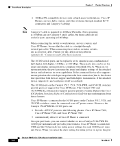
...16 17 18 19 20 21 22 23 24 23X 14X 24X 10/100 inline-power ports Figure 1-6 Catalyst 3548 XL Switch 1 2 GBIC module slots 28010 SYSTEM RPS 12 1X 34 56 78 9 10 11 12 13 ...31 32 31X 33 34 33X 35 36 37 38 39 40 41 42 43 44 45 46 47 48 STATUS UTIL DUPLX SPEED 2X 47X 1 MODE 16X 18X 32X 34X 2 48X 10/100 ports GBIC ...and so on the Catalyst 3512, 3524, 3524-PWR, and 3548 XL switches are the left-most pair. The 10/100 switch ports can connect, up to any compatible network device: • 10BaseT-compatible devices such as workstations, Cisco IP Phones, and hubs...
...16 17 18 19 20 21 22 23 24 23X 14X 24X 10/100 inline-power ports Figure 1-6 Catalyst 3548 XL Switch 1 2 GBIC module slots 28010 SYSTEM RPS 12 1X 34 56 78 9 10 11 12 13 ...31 32 31X 33 34 33X 35 36 37 38 39 40 41 42 43 44 45 46 47 48 STATUS UTIL DUPLX SPEED 2X 47X 1 MODE 16X 18X 32X 34X 2 48X 10/100 ports GBIC ...and so on the Catalyst 3512, 3524, 3524-PWR, and 3548 XL switches are the left-most pair. The 10/100 switch ports can connect, up to any compatible network device: • 10BaseT-compatible devices such as workstations, Cisco IP Phones, and hubs...
Installation Guide
Page 32
... the attached device and advertises its own capabilities. The Catalyst 3548 and 3524-PWR XL switches also support per -port basis, you select the Auto setting for Cisco IP Phones. Pinouts for 100BaseTX traffic. However, the Catalyst 3524-PWR XL 10/100 ports can: • ... "Connector and Cable Specifications." The 10/100 switch ports can use a crossover cable. When connecting the switch to workstations, servers, routers, and Cisco IP Phones, be explicitly set to the 10/100 ports on a port, the port Catalyst 3500 Series XL Hardware Installation Guide 1-8 78-6456...
... the attached device and advertises its own capabilities. The Catalyst 3548 and 3524-PWR XL switches also support per -port basis, you select the Auto setting for Cisco IP Phones. Pinouts for 100BaseTX traffic. However, the Catalyst 3524-PWR XL 10/100 ports can: • ... "Connector and Cable Specifications." The 10/100 switch ports can use a crossover cable. When connecting the switch to workstations, servers, routers, and Cisco IP Phones, be explicitly set to the 10/100 ports on a port, the port Catalyst 3500 Series XL Hardware Installation Guide 1-8 78-6456...
Installation Guide
Page 33
... power source, and the second power source is inserted into a GBIC module slot on the switch. Refer to the documentation that came with the switch. You also can connect the Cisco IP Phone to a Catalyst 3524-PWR XL 10/100 port and to an AC power source for a GigaStack GBIC-to... a 1-Gbps stack configuration of up to it . The Auto setting is connected to nine Catalyst 3500 XL switches. Note GBIC modules are not factory-installed on a port, the port does not provide power even if a Cisco IP Phone is 1 meter. Chapter 1 Product Overview Front-Panel Description only provides power if...
... power source, and the second power source is inserted into a GBIC module slot on the switch. Refer to the documentation that came with the switch. You also can connect the Cisco IP Phone to a Catalyst 3524-PWR XL 10/100 port and to an AC power source for a GigaStack GBIC-to... a 1-Gbps stack configuration of up to it . The Auto setting is connected to nine Catalyst 3500 XL switches. Note GBIC modules are not factory-installed on a port, the port does not provide power even if a Cisco IP Phone is 1 meter. Chapter 1 Product Overview Front-Panel Description only provides power if...

Installation Guide
Page 34
Front-Panel Description Chapter 1 Product Overview Figure 1-7 Installing a 1000BaseX GBIC Module in the Switch Metal flap door 18965 1 SYSTEM RPS MODE STATUS UTIL DUPLX SPEED 2 3 1000BaseX GBIC module GBIC module slot Figure 1-8 Installing a GigaStack GBIC Module in the Switch Metal flap door 22081 1 SYSTEM RPS MODE STATUS UTIL DUPLX SPEED 2 3 1 2 GigaStack GBIC GBIC module slot 1-10 Catalyst 3500 Series XL Hardware Installation Guide 78-6456-04
Front-Panel Description Chapter 1 Product Overview Figure 1-7 Installing a 1000BaseX GBIC Module in the Switch Metal flap door 18965 1 SYSTEM RPS MODE STATUS UTIL DUPLX SPEED 2 3 1000BaseX GBIC module GBIC module slot Figure 1-8 Installing a GigaStack GBIC Module in the Switch Metal flap door 22081 1 SYSTEM RPS MODE STATUS UTIL DUPLX SPEED 2 3 1 2 GigaStack GBIC GBIC module slot 1-10 Catalyst 3500 Series XL Hardware Installation Guide 78-6456-04
Installation Guide
Page 35
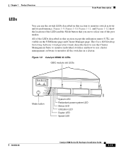
The Cisco IOS Desktop Switching Software Configuration Guide describes how to use the Cluster Management Suite to monitor individual switches and how to use cluster management software to monitor switch activity and its performance. Figure 1-9 Catalyst 3508G XL LEDs GBIC module slot LEDs 18961 1 SYSTEM 2 3 ... system LED Status LED Utilization LED Duplex LED Speed LED 78-6456-04 Catalyst 3500 Series XL Hardware Installation Guide 1-11 Chapter 1 Product Overview Front-Panel Description LEDs You can use the switch LEDs described in a cluster. Figure 1-9, Figure 1-10, Figure 1-11,...
The Cisco IOS Desktop Switching Software Configuration Guide describes how to use the Cluster Management Suite to monitor individual switches and how to use cluster management software to monitor switch activity and its performance. Figure 1-9 Catalyst 3508G XL LEDs GBIC module slot LEDs 18961 1 SYSTEM 2 3 ... system LED Status LED Utilization LED Duplex LED Speed LED 78-6456-04 Catalyst 3500 Series XL Hardware Installation Guide 1-11 Chapter 1 Product Overview Front-Panel Description LEDs You can use the switch LEDs described in a cluster. Figure 1-9, Figure 1-10, Figure 1-11,...

Installation Guide
Page 38
... is not functioning properly. System is receiving power but is not powered on page 2-17. 1-14 Catalyst 3500 Series XL Hardware Installation Guide 78-6456-04 System is functioning properly. Front-Panel Description Figure 1-12 Catalyst 3548 XL LEDs Port LEDs Chapter 1 Product Overview SYSTEM RPS STATUS UTIL DUPLX SPEED MODE 1 1X... is operating normally. Table 1-3 lists the LED colors and their meanings. For information on the System LED colors during POST, see the "Powering On the Switch and Running POST" section on .
... is not functioning properly. System is receiving power but is not powered on page 2-17. 1-14 Catalyst 3500 Series XL Hardware Installation Guide 78-6456-04 System is functioning properly. Front-Panel Description Figure 1-12 Catalyst 3548 XL LEDs Port LEDs Chapter 1 Product Overview SYSTEM RPS STATUS UTIL DUPLX SPEED MODE 1 1X... is operating normally. Table 1-3 lists the LED colors and their meanings. For information on the System LED colors during POST, see the "Powering On the Switch and Running POST" section on .
Installation Guide
Page 39
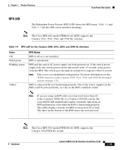
...the LED colors and their meanings. Note The Cisco RPS 600 (model PWR600-AC-RPS) supports the Catalyst 3512, 3524, 3548, and 3508 XL switches. If the switch power supply fails, the switch powers down , or a fan on page 1-23. The label on . The switch goes through its normal boot sequence when it ... powered on the bottom of the power supplies in the RPS could have failed. Note The Cisco RPS 300 (model PWR300-AC-RPS) supports the Catalyst 3524-PWR XL switch. 78-6456-04 Catalyst 3500 Series XL Hardware Installation Guide 1-15 RPS is connected but not functioning properly. RPS and...
...the LED colors and their meanings. Note The Cisco RPS 600 (model PWR600-AC-RPS) supports the Catalyst 3512, 3524, 3548, and 3508 XL switches. If the switch power supply fails, the switch powers down , or a fan on page 1-23. The label on . The switch goes through its normal boot sequence when it ... powered on the bottom of the power supplies in the RPS could have failed. Note The Cisco RPS 300 (model PWR300-AC-RPS) supports the Catalyst 3524-PWR XL switch. 78-6456-04 Catalyst 3500 Series XL Hardware Installation Guide 1-15 RPS is connected but not functioning properly. RPS and...
Installation Guide
Page 40
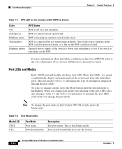
... the RPS. Table 1-7 and Table 1-8 explain how to the Cisco Redundant Power System 300 Hardware Installation Guide. For more information about the individual ports. The port modes (Table 1-6) determine the type of the switch is backing up another switch in use by the switch. 1-16 Catalyst 3500 Series XL Hardware Installation Guide 78-6456-04...
... the RPS. Table 1-7 and Table 1-8 explain how to the Cisco Redundant Power System 300 Hardware Installation Guide. For more information about the individual ports. The port modes (Table 1-6) determine the type of the switch is backing up another switch in use by the switch. 1-16 Catalyst 3500 Series XL Hardware Installation Guide 78-6456-04...


