

Software Guide
Page 31
... Catalyst 4000 series switches. Product Overview CH A P T E R 1 The Catalyst enterprise LAN switches facilitate the migration from traditional shared-hub LANs to the Catalyst 4000 Series Installation Guide, Catalyst 4500 Series Switch Installation Guide, and the Catalyst 4912G Installation Guide. Table 1-1 Catalyst 4000 Series and Catalyst 4500 Series Switches Product Number Catalyst 4000 Series WS-C4003 WS-C4006 Chassis Description Catalyst 4003 • Modular 3-slot chassis...
... Catalyst 4000 series switches. Product Overview CH A P T E R 1 The Catalyst enterprise LAN switches facilitate the migration from traditional shared-hub LANs to the Catalyst 4000 Series Installation Guide, Catalyst 4500 Series Switch Installation Guide, and the Catalyst 4912G Installation Guide. Table 1-1 Catalyst 4000 Series and Catalyst 4500 Series Switches Product Number Catalyst 4000 Series WS-C4003 WS-C4006 Chassis Description Catalyst 4003 • Modular 3-slot chassis...

Software Guide
Page 32
...; 48 10/100BASE-TX Fast Ethernet ports Catalyst 4500 Series, Catalyst 2948G, Catalyst 2980G Switches Software Configuration Guide-Release 8.1 1-2 78-15486-01 Catalyst 2948G Switch Chapter 1 Product Overview Table 1-1 Catalyst 4000 Series and Catalyst 4500 Series Switches (continued) Product Number WS-C4912G Catalyst 4500 Series WS-C4503 WS-C4506 Chassis Description Catalyst 4912G • Fixed-configuration switch • 12-Gbps backplane • Optional...
...; 48 10/100BASE-TX Fast Ethernet ports Catalyst 4500 Series, Catalyst 2948G, Catalyst 2980G Switches Software Configuration Guide-Release 8.1 1-2 78-15486-01 Catalyst 2948G Switch Chapter 1 Product Overview Table 1-1 Catalyst 4000 Series and Catalyst 4500 Series Switches (continued) Product Number WS-C4912G Catalyst 4500 Series WS-C4503 WS-C4506 Chassis Description Catalyst 4912G • Fixed-configuration switch • 12-Gbps backplane • Optional...

Software Guide
Page 33
... and 2980G Installation Guide. For descriptions of the Catalyst 2980G switch hardware, refer to the Catalyst 4500 Series, Catalyst 2948G, and Catalyst 2980G Switches Command Reference. 78-15486-01 Catalyst 4500 Series, Catalyst 2948G, Catalyst 2980G Switches Software Configuration Guide-Release 8.1 1-3 Table 1-3 Catalyst 2980G Switch Product Number WS-C2980G-A Chassis Description Catalyst 2980G • Fixed-configuration switch • 12-Gbps backplane • Optional redundant power...
... and 2980G Installation Guide. For descriptions of the Catalyst 2980G switch hardware, refer to the Catalyst 4500 Series, Catalyst 2948G, and Catalyst 2980G Switches Command Reference. 78-15486-01 Catalyst 4500 Series, Catalyst 2948G, Catalyst 2980G Switches Software Configuration Guide-Release 8.1 1-3 Table 1-3 Catalyst 2980G Switch Product Number WS-C2980G-A Chassis Description Catalyst 2980G • Fixed-configuration switch • 12-Gbps backplane • Optional redundant power...

Software Guide
Page 76
... and Link Aggregation Control Protocol (LACP) allow ports with up to the remaining ports within the EtherChannel. Catalyst 4500 Series, Catalyst 2948G, Catalyst 2980G Switches Software Configuration Guide-Release 8.1 6-2 78-15486-01 PAgP and LACP Chapter 6 Configuring Fast EtherChannel and Gigabit ... Gigabit Ethernet Ports." Hardware Support for EtherChannel EtherChannel support is 126 for a 6-slot chassis. An EtherChannel bundle can be run only on Cisco switches and those switches released by the spanning tree feature, the maximum supported number of channels is hardware dependent...
... and Link Aggregation Control Protocol (LACP) allow ports with up to the remaining ports within the EtherChannel. Catalyst 4500 Series, Catalyst 2948G, Catalyst 2980G Switches Software Configuration Guide-Release 8.1 6-2 78-15486-01 PAgP and LACP Chapter 6 Configuring Fast EtherChannel and Gigabit ... Gigabit Ethernet Ports." Hardware Support for EtherChannel EtherChannel support is 126 for a 6-slot chassis. An EtherChannel bundle can be run only on Cisco switches and those switches released by the spanning tree feature, the maximum supported number of channels is hardware dependent...

Software Guide
Page 110
... information, allowing them to 4094. If you replace the chassis with 802.1D STP, 802.1w, the Rapid Spanning Tree Protocol (RSTP), and the Cisco PVST+ architecture. If the switch is an amendment to a Catalyst 4500 Series Switch" section on migrating your supervisor engine. If the other switches in VLAN 1, the new bridge ID priority will...
... information, allowing them to 4094. If you replace the chassis with 802.1D STP, 802.1w, the Rapid Spanning Tree Protocol (RSTP), and the Cisco PVST+ architecture. If the switch is an amendment to a Catalyst 4500 Series Switch" section on migrating your supervisor engine. If the other switches in VLAN 1, the new bridge ID priority will...
Software Guide
Page 375
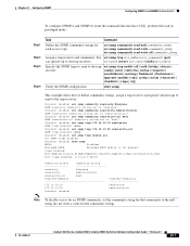
....16.10.20 read-write-all All SNMP traps enabled. set snmp community read-only community_string set snmp community read -write-all | auth | bridge | chassis | config | entity | entityfru | envfan | envpower | envshutdown | envtemp | flashinsert | flashremove | ippermit | module | stpx | syslog | system ...2 Step 3 Step 4 Task Command Define the SNMP community strings for the community string). 78-15486-01 Catalyst 4500 Series, Catalyst 2948G, Catalyst 2980G Switches Software Configuration Guide-Release 8.1 24-7 Console> (enable) set snmp community read-write-all Root SNMP read...
....16.10.20 read-write-all All SNMP traps enabled. set snmp community read-only community_string set snmp community read -write-all | auth | bridge | chassis | config | entity | entityfru | envfan | envpower | envshutdown | envtemp | flashinsert | flashremove | ippermit | module | stpx | syslog | system ...2 Step 3 Step 4 Task Command Define the SNMP community strings for the community string). 78-15486-01 Catalyst 4500 Series, Catalyst 2948G, Catalyst 2980G Switches Software Configuration Guide-Release 8.1 24-7 Console> (enable) set snmp community read-write-all Root SNMP read...

Software Guide
Page 388
...Enable RMON. Console> (enable) show snmp RMON: Enabled Extended RMON: Extended RMON module is not present Traps Enabled: Port,Module,Chassis,Bridge,Repeater,Vtp,Auth,ippermit,Vmps,config,entity,stpx Port Traps Enabled: 1/1-2,4/1-48,5/1 Community-Access Community-String read-only Everyone read-write...how to enable RMON and how to verify that RMON is disabled by the supervisor engine software. 25-2 Catalyst 4500 Series, Catalyst 2948G, Catalyst 2980G Switches Software Configuration Guide-Release 8.1 78-15486-01 Verify that RMON is available only on an NMS that are ...
...Enable RMON. Console> (enable) show snmp RMON: Enabled Extended RMON: Extended RMON module is not present Traps Enabled: Port,Module,Chassis,Bridge,Repeater,Vtp,Auth,ippermit,Vmps,config,entity,stpx Port Traps Enabled: 1/1-2,4/1-48,5/1 Community-Access Community-String read-only Everyone read-write...how to enable RMON and how to verify that RMON is disabled by the supervisor engine software. 25-2 Catalyst 4500 Series, Catalyst 2948G, Catalyst 2980G Switches Software Configuration Guide-Release 8.1 78-15486-01 Verify that RMON is available only on an NMS that are ...

Software Guide
Page 412
...set the system clock and display the current date and time: Console> (enable) set banner motd c message_of_the_day c - 27-4 Catalyst 4500 Series, Catalyst 2948G, Catalyst 2980G Switches Software Configuration Guide-Release 8.1 78-15486-01 Command set time [day_of_week] [mm/dd/yy] [hh:mm:ss] show time Fri...using the Network Time Protocol (NTP). Setting the System Clock Chapter 27 Administering the Switch disable 9600 0% 0% Wed Apr 24 2002, 15:46:01 Power Capacity of the Chassis:2 supplies WARNING:Power supplies of different values have been inserted System Name System Location ...
...set the system clock and display the current date and time: Console> (enable) set banner motd c message_of_the_day c - 27-4 Catalyst 4500 Series, Catalyst 2948G, Catalyst 2980G Switches Software Configuration Guide-Release 8.1 78-15486-01 Command set time [day_of_week] [mm/dd/yy] [hh:mm:ss] show time Fri...using the Network Time Protocol (NTP). Setting the System Clock Chapter 27 Administering the Switch disable 9600 0% 0% Wed Apr 24 2002, 15:46:01 Power Capacity of the Chassis:2 supplies WARNING:Power supplies of different values have been inserted System Name System Location ...
Software Guide
Page 423
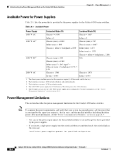
... have a predetermined current sharing ratio. Modules are less than the maximum available power for the chassis and inline power for each power supply. 78-15486-01 Catalyst 4500 Series, Catalyst 2948G, Catalyst 2980G Switches Software Configuration Guide-Release 8.1 28-3 If you set to redundant mode and only one power supply is P + (P * ratio). • See Table...
... have a predetermined current sharing ratio. Modules are less than the maximum available power for the chassis and inline power for each power supply. 78-15486-01 Catalyst 4500 Series, Catalyst 2948G, Catalyst 2980G Switches Software Configuration Guide-Release 8.1 28-3 If you set to redundant mode and only one power supply is P + (P * ratio). • See Table...
Software Guide
Page 424
... the power requirements for the installed modules to exceed the power that is provided by the power supplies for the Catalyst 4500 series switches. The chassis power includes power for the Catalyst 4500 series switches. The backplane consumes 10 W in both redundant and combined mode. 3. The 1400 W DC power supply has 0.75 efficiency. The inline...
... the power requirements for the installed modules to exceed the power that is provided by the power supplies for the Catalyst 4500 series switches. The chassis power includes power for the Catalyst 4500 series switches. The backplane consumes 10 W in both redundant and combined mode. 3. The 1400 W DC power supply has 0.75 efficiency. The inline...

Software Guide
Page 425
.... • If the power requirements for the installed modules exceed the power that is working properly. 78-15486-01 Catalyst 4500 Series, Catalyst 2948G, Catalyst 2980G Switches Software Configuration Guide-Release 8.1 28-5 The power supply fan status is 96 percent efficient, and system power has only 75...display shows the power as it is installed in the chassis. 1400 W DC Power Supply Guidelines and Restrictions This section describes the guidelines and restrictions for using a 1400 W DC power supply in the Catalyst 4500 series switches: Caution Do not use the set power dcinput command ...
.... • If the power requirements for the installed modules exceed the power that is working properly. 78-15486-01 Catalyst 4500 Series, Catalyst 2948G, Catalyst 2980G Switches Software Configuration Guide-Release 8.1 28-5 The power supply fan status is 96 percent efficient, and system power has only 75...display shows the power as it is installed in the chassis. 1400 W DC Power Supply Guidelines and Restrictions This section describes the guidelines and restrictions for using a 1400 W DC power supply in the Catalyst 4500 series switches: Caution Do not use the set power dcinput command ...

Software Guide
Page 426
... mode might not support a fully loaded chassis. You can provide. The power management feature for the Catalyst 4500 series switches, see the "Understanding How Power Management Works on the Catalyst 4500 Series Switches" section on page 28-1. some switch configurations require more information, refer to manage power for the Catalyst 4006 switch. Understanding How Power Management Works on...
... mode might not support a fully loaded chassis. You can provide. The power management feature for the Catalyst 4500 series switches, see the "Understanding How Power Management Works on the Catalyst 4500 Series Switches" section on page 28-1. some switch configurations require more information, refer to manage power for the Catalyst 4006 switch. Understanding How Power Management Works on...

Software Guide
Page 427
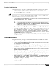
... the module power usage of your chassis. Chapter 28 Power Management Understanding How Power Management Works on the Catalyst 4006 Switch If you choose to use a 1+1 redundancy configuration, you try to configure the switch to operate in the chassis; In the 1+1 redundancy mode, ...the 1+1 redundancy mode in the chassis (at boot up the power that require more power than the single power supply provides, the switch places the newly inserted module into reset mode. 78-15486-01 Catalyst 4500 Series, Catalyst 2948G, Catalyst 2980G Switches Software Configuration Guide-Release 8.1 ...
... the module power usage of your chassis. Chapter 28 Power Management Understanding How Power Management Works on the Catalyst 4006 Switch If you choose to use a 1+1 redundancy configuration, you try to configure the switch to operate in the chassis; In the 1+1 redundancy mode, ...the 1+1 redundancy mode in the chassis (at boot up the power that require more power than the single power supply provides, the switch places the newly inserted module into reset mode. 78-15486-01 Catalyst 4500 Series, Catalyst 2948G, Catalyst 2980G Switches Software Configuration Guide-Release 8.1 ...

Software Guide
Page 428
... WS-X4148-RJ modules-65 W each (600 W total) • Fan tray-25 W 28-8 Catalyst 4500 Series, Catalyst 2948G, Catalyst 2980G Switches Software Configuration Guide-Release 8.1 78-15486-01 however, the switch still has only 400 W available. It requires 445 W and cannot be used in 1+1 redundancy mode,...You must remove the failed 400 W power supply so that are placed in your Catalyst 4006 switch and you configure the chassis correctly, the switch does not enter the evaluation cycle. Modules that the switch can either remove the extra modules or change to 2+1 redundancy mode, each (...
... WS-X4148-RJ modules-65 W each (600 W total) • Fan tray-25 W 28-8 Catalyst 4500 Series, Catalyst 2948G, Catalyst 2980G Switches Software Configuration Guide-Release 8.1 78-15486-01 however, the switch still has only 400 W available. It requires 445 W and cannot be used in 1+1 redundancy mode,...You must remove the failed 400 W power supply so that are placed in your Catalyst 4006 switch and you configure the chassis correctly, the switch does not enter the evaluation cycle. Modules that the switch can either remove the extra modules or change to 2+1 redundancy mode, each (...

Software Guide
Page 430
... the Catalyst 4500 series chassis. Because 32,769 is greater than 32,768, this switch cannot become the root switch. • The Catalyst 4006 switch is greater than 32,768, this switch cannot become the root switch. If the other switches in the network are two scenarios to reflect the new root switch. 28-10 Catalyst 4500 Series, Catalyst 2948G, Catalyst 2980G Switches Software...
... the Catalyst 4500 series chassis. Because 32,769 is greater than 32,768, this switch cannot become the root switch. • The Catalyst 4006 switch is greater than 32,768, this switch cannot become the root switch. If the other switches in the network are two scenarios to reflect the new root switch. 28-10 Catalyst 4500 Series, Catalyst 2948G, Catalyst 2980G Switches Software...

Software Guide
Page 431
... Inline Power Works The Catalyst 4006 switch and the Catalyst 4500 series switches can configure the switch to stop supplying power to the powered device and to disable the detection mechanism. If you need to the switch port, the switch cannot power the second phone. Table 28-3 Switch Components Supporting Inline Power Switch Chassis Catalyst 4006 Catalyst 4503 Catalyst 4506 Modules WS-X4148...
... Inline Power Works The Catalyst 4006 switch and the Catalyst 4500 series switches can configure the switch to stop supplying power to the powered device and to disable the detection mechanism. If you need to the switch port, the switch cannot power the second phone. Table 28-3 Switch Components Supporting Inline Power Switch Chassis Catalyst 4006 Catalyst 4503 Catalyst 4506 Modules WS-X4148...

Software Guide
Page 437
...Peak Peak-Time disable 9600 0% 0% Fri May 31 2002, 10:24:04 Power Capacity of the Chassis: 1 supply 78-15486-01 Catalyst 4500 Series, Catalyst 2948G, Catalyst 2980G Switches Software Configuration Guide-Release 8.1 28-17 Command show system This example shows how to display the output... for the switch: Console> (enable) set power budget 1 Warning: Your power supply budget will be constrained to ...
...Peak Peak-Time disable 9600 0% 0% Fri May 31 2002, 10:24:04 Power Capacity of the Chassis: 1 supply 78-15486-01 Catalyst 4500 Series, Catalyst 2948G, Catalyst 2980G Switches Software Configuration Guide-Release 8.1 28-17 Command show system This example shows how to display the output... for the switch: Console> (enable) set power budget 1 Warning: Your power supply budget will be constrained to ...
Software Guide
Page 441
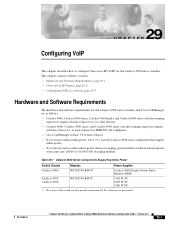
... Series Components Supporting Inline Power Switch Chassis Catalyst 4006 Catalyst 4503 Catalyst 4506 Modules WS-X4148-RJ45V1 WS-X4148-RJ45V Power Supplies Catalyst 4000 Family Power Entry Module (PEM) 1300 W AC 2800 W AC 1400 W DC 1. This... for the Catalyst 4500 series switches and Cisco CallManager are as follows: • Catalyst 4006, Catalyst 4500 series, Catalyst 5000 family, and Catalyst 6500 series switches running supervisor engine software release 6.1(1) or later releases • Catalyst 4006, Catalyst 4500 series, and Catalyst 6500 series switches running supervisor ...
... Series Components Supporting Inline Power Switch Chassis Catalyst 4006 Catalyst 4503 Catalyst 4506 Modules WS-X4148-RJ45V1 WS-X4148-RJ45V Power Supplies Catalyst 4000 Family Power Entry Module (PEM) 1300 W AC 2800 W AC 1400 W DC 1. This... for the Catalyst 4500 series switches and Cisco CallManager are as follows: • Catalyst 4006, Catalyst 4500 series, Catalyst 5000 family, and Catalyst 6500 series switches running supervisor engine software release 6.1(1) or later releases • Catalyst 4006, Catalyst 4500 series, and Catalyst 6500 series switches running supervisor ...

Software Guide
Page 555
... between modules installed in the chassis. • SE3 handles traffic for SE3, or vice versa, must go through SE2, which could potentially create congestion. The switch acceleration feature reduces internal traffic congestion by creating a full-mesh connection between SE1 and SE3. 78-15486-01 Catalyst 4500 Series, Catalyst 2948G, Catalyst 2980G Switches Software Configuration Guide-Release...
... between modules installed in the chassis. • SE3 handles traffic for SE3, or vice versa, must go through SE2, which could potentially create congestion. The switch acceleration feature reduces internal traffic congestion by creating a full-mesh connection between SE1 and SE3. 78-15486-01 Catalyst 4500 Series, Catalyst 2948G, Catalyst 2980G Switches Software Configuration Guide-Release...

