

Software Guide
Page 17
...01 Configuring a Login Banner 27-4 Clearing the Login Banner 27-5 Enabling or Disabling the "Cisco Systems Console" Telnet Login Banner 27-5 Defining and Using Command Aliases 27-6 Defining and ...Power Management 28-1 Understanding How Power Management Works on the Catalyst 4500 Series Switches 28-1 Power Management Overview 28-2 Understanding Power Management Modes 28-2 Available Power for Power Supplies 28-4 Power Management Limitations 28-4 1400 W DC Power Supply Guidelines and Restrictions 28-5 Understanding How Power Management Works on the Catalyst 4006 Switch 28-6 Understanding Power...
...01 Configuring a Login Banner 27-4 Clearing the Login Banner 27-5 Enabling or Disabling the "Cisco Systems Console" Telnet Login Banner 27-5 Defining and Using Command Aliases 27-6 Defining and ...Power Management 28-1 Understanding How Power Management Works on the Catalyst 4500 Series Switches 28-1 Power Management Overview 28-2 Understanding Power Management Modes 28-2 Available Power for Power Supplies 28-4 Power Management Limitations 28-4 1400 W DC Power Supply Guidelines and Restrictions 28-5 Understanding How Power Management Works on the Catalyst 4006 Switch 28-6 Understanding Power...

Software Guide
Page 31
... 3-slot chassis • Optional redundant power supplies Catalyst 4006 • Modular 6-slot chassis • 30-Gbps backplane • Two power supplies with optional third power supply 78-15486-01 Catalyst 4500 Series, Catalyst 2948G, Catalyst 2980G Switches Software Configuration Guide-Release 8.1 1-1 These switches provide switched connections to the Catalyst 4000 Series Installation Guide, Catalyst 4500 Series Switch Installation Guide, and the Catalyst 4912G Installation Guide. Product Overview...
... 3-slot chassis • Optional redundant power supplies Catalyst 4006 • Modular 6-slot chassis • 30-Gbps backplane • Two power supplies with optional third power supply 78-15486-01 Catalyst 4500 Series, Catalyst 2948G, Catalyst 2980G Switches Software Configuration Guide-Release 8.1 1-1 These switches provide switched connections to the Catalyst 4000 Series Installation Guide, Catalyst 4500 Series Switch Installation Guide, and the Catalyst 4912G Installation Guide. Product Overview...

Software Guide
Page 32
... Fast Ethernet ports Catalyst 4500 Series, Catalyst 2948G, Catalyst 2980G Switches Software Configuration Guide-Release 8.1 1-2 78-15486-01 Catalyst 2948G Switch Chapter 1 Product Overview Table 1-1 Catalyst 4000 Series and Catalyst 4500 Series Switches (continued) Product Number WS-C4912G Catalyst 4500 Series WS-C4503 WS-C4506 Chassis Description Catalyst 4912G • Fixed-configuration switch • 12-Gbps backplane • Optional redundant power supplies • 12...
... Fast Ethernet ports Catalyst 4500 Series, Catalyst 2948G, Catalyst 2980G Switches Software Configuration Guide-Release 8.1 1-2 78-15486-01 Catalyst 2948G Switch Chapter 1 Product Overview Table 1-1 Catalyst 4000 Series and Catalyst 4500 Series Switches (continued) Product Number WS-C4912G Catalyst 4500 Series WS-C4503 WS-C4506 Chassis Description Catalyst 4912G • Fixed-configuration switch • 12-Gbps backplane • Optional redundant power supplies • 12...

Software Guide
Page 33
... 1-3 describes the Catalyst 2980G switch. Chapter 1 Product Overview Catalyst 2980G Switch Catalyst 2980G Switch Note For installation information and a complete description of the available CLI commands, refer to the Catalyst 2948G and 2980G Installation Guide. Table 1-3 Catalyst 2980G Switch Product Number WS-C2980G-A Chassis Description Catalyst 2980G • Fixed-configuration switch • 12-Gbps backplane • Optional redundant power supplies • Two 1000BASE...
... 1-3 describes the Catalyst 2980G switch. Chapter 1 Product Overview Catalyst 2980G Switch Catalyst 2980G Switch Note For installation information and a complete description of the available CLI commands, refer to the Catalyst 2948G and 2980G Installation Guide. Table 1-3 Catalyst 2980G Switch Product Number WS-C2980G-A Chassis Description Catalyst 2980G • Fixed-configuration switch • 12-Gbps backplane • Optional redundant power supplies • Two 1000BASE...

Software Guide
Page 373
...engine module software (see Chapter 25, "Configuring RMON") • RMON and RMON2 on an external SwitchProbe device 78-15486-01 Catalyst 4500 Series, Catalyst 2948G, Catalyst 2980G Switches Software Configuration Guide-Release 8.1 24-5 Read-only-Gives only read and write access to all objects in response to an NMS message...used to notify an NMS that a significant event has occurred at least one of the three community string definitions on the switch. When power supply errors occur • SNMP community strings-SNMP community strings authenticate access to community strings -
...engine module software (see Chapter 25, "Configuring RMON") • RMON and RMON2 on an external SwitchProbe device 78-15486-01 Catalyst 4500 Series, Catalyst 2948G, Catalyst 2980G Switches Software Configuration Guide-Release 8.1 24-5 Read-only-Gives only read and write access to all objects in response to an NMS message...used to notify an NMS that a significant event has occurred at least one of the three community string definitions on the switch. When power supply errors occur • SNMP community strings-SNMP community strings authenticate access to community strings -

Software Guide
Page 412
... following the ending delimiter are discarded. Setting the System Clock Chapter 27 Administering the Switch disable 9600 0% 0% Wed Apr 24 2002, 15:46:01 Power Capacity of the Chassis:2 supplies WARNING:Power supplies of the banner text. Display the current date and time. After entering the ending...can create a single or multiline message-of the day. Characters following the motd keyword is used to the switch. Command set banner motd c message_of_the_day c - 27-4 Catalyst 4500 Series, Catalyst 2948G, Catalyst 2980G Switches Software Configuration Guide-Release 8.1 78-15486-01
... following the ending delimiter are discarded. Setting the System Clock Chapter 27 Administering the Switch disable 9600 0% 0% Wed Apr 24 2002, 15:46:01 Power Capacity of the Chassis:2 supplies WARNING:Power supplies of the banner text. Display the current date and time. After entering the ending...can create a single or multiline message-of the day. Characters following the motd keyword is used to the switch. Command set banner motd c message_of_the_day c - 27-4 Catalyst 4500 Series, Catalyst 2948G, Catalyst 2980G Switches Software Configuration Guide-Release 8.1 78-15486-01
Software Guide
Page 422
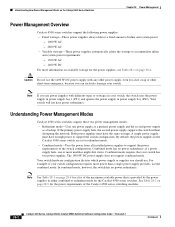
... one or more modules might shut down. A single power supply must have power redundancy. Your switch hardware configuration dictates which power supply or supplies you should use. Understanding How Power Management Works on the Catalyst 4500 Series Switches Chapter 28 Power Management Power Management Overview Catalyst 4500 series switches support the following power supplies: • Fixed wattage-These power supplies always deliver a fixed amount of inline and system...
... one or more modules might shut down. A single power supply must have power redundancy. Your switch hardware configuration dictates which power supply or supplies you should use. Understanding How Power Management Works on the Catalyst 4500 Series Switches Chapter 28 Power Management Power Management Overview Catalyst 4500 series switches support the following power supplies: • Fixed wattage-These power supplies always deliver a fixed amount of inline and system...
Software Guide
Page 423
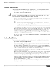
... using fixed power supplies, choose a power supply that the chassis and inline power requirements are less than the maximum available power for the chassis and inline power for the power supply. Your switch will not have no power redundancy. • The 1400 W DC power supply does not support combined mode. Chapter 28 Power Management Understanding How Power Management Works on the Catalyst 4500 Series Switches Redundant Mode...
... using fixed power supplies, choose a power supply that the chassis and inline power requirements are less than the maximum available power for the chassis and inline power for the power supply. Your switch will not have no power redundancy. • The 1400 W DC power supply does not support combined mode. Chapter 28 Power Management Understanding How Power Management Works on the Catalyst 4500 Series Switches Redundant Mode...
Software Guide
Page 424
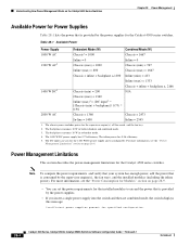
... on page 28-4. Note To compute the power requirements and verify that your system has enough power, add the power that is provided by the power supplies for the Catalyst 4500 series switches. Understanding How Power Management Works on the Catalyst 4500 Series Switches Chapter 28 Power Management Available Power for Power Supplies Table 28-1 lists the power that is consumed by the supervisor engine...
... on page 28-4. Note To compute the power requirements and verify that your system has enough power, add the power that is provided by the power supplies for the Catalyst 4500 series switches. Understanding How Power Management Works on the Catalyst 4500 Series Switches Chapter 28 Power Management Available Power for Power Supplies Table 28-1 lists the power that is consumed by the supervisor engine...

Software Guide
Page 425
... power supply in the Catalyst 4500 series switches: Caution Do not use the 1400 W DC power supply with any other power supply, even for a hot swap or other short-term emergency, because you can seriously damage your switch. • The 1400 W DC power supply works with a variety of the power supplies into the switch, the switch places the newly inserted module into the 1400 W DC power supply...
... power supply in the Catalyst 4500 series switches: Caution Do not use the 1400 W DC power supply with any other power supply, even for a hot swap or other short-term emergency, because you can seriously damage your switch. • The 1400 W DC power supply works with a variety of the power supplies into the switch, the switch places the newly inserted module into the 1400 W DC power supply...

Software Guide
Page 426
... primary power supplies to the Catalyst 4000 Series Switch Installation Guide. Note For information on power management for the system. You need to three power supplies. some switch configurations require more information, refer to operate a fully loaded Catalyst 4006 chassis. For more power than the power that you use a 400 W power supply and a 650 W power supply, the switch acts as if there were two 400 W power supplies. You...
... primary power supplies to the Catalyst 4000 Series Switch Installation Guide. Note For information on power management for the system. You need to three power supplies. some switch configurations require more information, refer to operate a fully loaded Catalyst 4006 chassis. For more power than the power that you use a 400 W power supply and a 650 W power supply, the switch acts as if there were two 400 W power supplies. You...

Software Guide
Page 427
.... 1+1 Redundancy Mode Guidelines and Restrictions This section describes the guidelines and restrictions for the Catalyst 4006 switch. Two 650 W power supplies supply only 750 W; Two 400 W power supplies provide 750 W. If you insert a module or change the system configuration from a single power supply. If you power down a chassis that are already operating in 1+1 redundancy mode with a valid module configuration and...
.... 1+1 Redundancy Mode Guidelines and Restrictions This section describes the guidelines and restrictions for the Catalyst 4006 switch. Two 650 W power supplies supply only 750 W; Two 400 W power supplies provide 750 W. If you insert a module or change the system configuration from a single power supply. If you power down a chassis that are already operating in 1+1 redundancy mode with a valid module configuration and...

Software Guide
Page 428
... an operational state. The evaluation process may require several cycles to 2+1 redundancy mode. If the power requirement of 400 W. The switch may require several evaluation cycles to stabilize the system.You can use a 400 W power supply and a 650 W power supply in your Catalyst 4006 switch and you use the available 650 W. If you configure the chassis correctly, the...
... an operational state. The evaluation process may require several cycles to 2+1 redundancy mode. If the power requirement of 400 W. The switch may require several evaluation cycles to stabilize the system.You can use a 400 W power supply and a 650 W power supply in your Catalyst 4006 switch and you use the available 650 W. If you configure the chassis correctly, the...

Software Guide
Page 431
... the Catalyst 4500 series switches can utilize inline power. Note A powered device is any device that requires external power or can sense if a powered device is power on the module to detect and apply inline power automatically if the end station requires power. Table 28-3 Switch Components Supporting Inline Power Switch Chassis Catalyst 4006 Catalyst 4503 Catalyst 4506 Modules WS-X4148-RJ45V WS-X4148-RJ45V Power Supplies Catalyst...
... the Catalyst 4500 series switches can utilize inline power. Note A powered device is any device that requires external power or can sense if a powered device is power on the module to detect and apply inline power automatically if the end station requires power. Table 28-3 Switch Components Supporting Inline Power Switch Chassis Catalyst 4006 Catalyst 4503 Catalyst 4506 Modules WS-X4148-RJ45V WS-X4148-RJ45V Power Supplies Catalyst...

Software Guide
Page 435
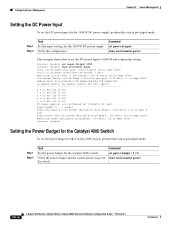
... Power supplies are configured for 2500Watts DC input Power Budget is : 1 supply Power Available to the System (excluding voice power): 1000 Watts (83.33 Amps @12V) Power Drawn from the System (excluding voice power): 516 Watts (43.00 Amps @12V) Remaining Power (excluding voice power): 484 Watts (40.33 Amps @12V) Console>(enable) Setting Combined Mode on the Catalyst 4500 Series Switches...
... Power supplies are configured for 2500Watts DC input Power Budget is : 1 supply Power Available to the System (excluding voice power): 1000 Watts (83.33 Amps @12V) Power Drawn from the System (excluding voice power): 516 Watts (43.00 Amps @12V) Remaining Power (excluding voice power): 484 Watts (40.33 Amps @12V) Console>(enable) Setting Combined Mode on the Catalyst 4500 Series Switches...
Software Guide
Page 436
... 830.562 15.400 6 0.00 830.562 15.400 DC Power supplies are configured for 5000Watts DC input Power Budget is : 1 supply Power Available to 5000 W and confirm the setting: Console> (enable) set power dcinput 5000 Console> (enable) show environment power 28-16 Catalyst 4500 Series, Catalyst 2948G, Catalyst 2980G Switches Software Configuration Guide-Release 8.1 78-15486-01 Verify the configuration.
... 830.562 15.400 6 0.00 830.562 15.400 DC Power supplies are configured for 5000Watts DC input Power Budget is : 1 supply Power Available to 5000 W and confirm the setting: Console> (enable) set power dcinput 5000 Console> (enable) show environment power 28-16 Catalyst 4500 Series, Catalyst 2948G, Catalyst 2980G Switches Software Configuration Guide-Release 8.1 78-15486-01 Verify the configuration.

Software Guide
Page 437
... Chassis: 1 supply 78-15486-01 Catalyst 4500 Series, Catalyst 2948G, Catalyst 2980G Switches Software Configuration Guide-Release 8.1 28-17 Chapter 28 Power Management Configuring Power Management This example shows how to set the power budget to 1 (1+1 redundancy mode) and display the power budget and current power usage for the show system command with mixed power supplies: Switch# show environment power Total Inline Power Available:0 Watt...
... Chassis: 1 supply 78-15486-01 Catalyst 4500 Series, Catalyst 2948G, Catalyst 2980G Switches Software Configuration Guide-Release 8.1 28-17 Chapter 28 Power Management Configuring Power Management This example shows how to set the power budget to 1 (1+1 redundancy mode) and display the power budget and current power usage for the show system command with mixed power supplies: Switch# show environment power Total Inline Power Available:0 Watt...

Software Guide
Page 438
... the current nondefault configuration to configure inline power for the Catalyst 4500 series switches and the Catalyst 4006 switch. If you have two power supplies, set port inlinepower mod/port {[auto | static] [max-wattage] | off} 28-18 Catalyst 4500 Series, Catalyst 2948G, Catalyst 2980G Switches Software Configuration Guide-Release 8.1 78-15486-01 Configuring Inline Power These sections show how to write memory...
... the current nondefault configuration to configure inline power for the Catalyst 4500 series switches and the Catalyst 4006 switch. If you have two power supplies, set port inlinepower mod/port {[auto | static] [max-wattage] | off} 28-18 Catalyst 4500 Series, Catalyst 2948G, Catalyst 2980G Switches Software Configuration Guide-Release 8.1 78-15486-01 Configuring Inline Power These sections show how to write memory...
Software Guide
Page 441
... Software Requirements, page 29-1 • Overview of inline power per module. 78-15486-01 Catalyst 4500 Series, Catalyst 2948G, Catalyst 2980G Switches Software Configuration Guide-Release 8.1 29-1 Table 29-1 Catalyst 4500 Series Components Supporting Inline Power Switch Chassis Catalyst 4006 Catalyst 4503 Catalyst 4506 Modules WS-X4148-RJ45V1 WS-X4148-RJ45V Power Supplies Catalyst 4000 Family Power Entry Module (PEM) 1300 W AC 2800 W AC 1400...
... Software Requirements, page 29-1 • Overview of inline power per module. 78-15486-01 Catalyst 4500 Series, Catalyst 2948G, Catalyst 2980G Switches Software Configuration Guide-Release 8.1 29-1 Table 29-1 Catalyst 4500 Series Components Supporting Inline Power Switch Chassis Catalyst 4006 Catalyst 4503 Catalyst 4506 Modules WS-X4148-RJ45V1 WS-X4148-RJ45V Power Supplies Catalyst 4000 Family Power Entry Module (PEM) 1300 W AC 2800 W AC 1400...
Software Guide
Page 593
... VLANs configuring 10-13 dynamic VLAN membership 12-14 software support 10-5 B BackboneFast adding a switch (figure) 8-7 78-15486-01 Catalyst 4500 Series, Catalyst 2948G, Catalyst 2980G Switches Software Configuration Guide-Release 8.1 IN-1 INDEX Numerics 10/100 port speed, setting 4-4 1400W DC power supply 28-5 802.1Q example 11-9, 11-19 mapping VLANs to ISL 10-11 overview...
... VLANs configuring 10-13 dynamic VLAN membership 12-14 software support 10-5 B BackboneFast adding a switch (figure) 8-7 78-15486-01 Catalyst 4500 Series, Catalyst 2948G, Catalyst 2980G Switches Software Configuration Guide-Release 8.1 IN-1 INDEX Numerics 10/100 port speed, setting 4-4 1400W DC power supply 28-5 802.1Q example 11-9, 11-19 mapping VLANs to ISL 10-11 overview...

