

Software Guide
Page 25
... publications are available for the Catalyst enterprise LAN switches: • Catalyst 4000 Series Switch Installation Guide • Catalyst 4500 Series Switch Installation Guide • Catalyst 4912G Installation Guide • Catalyst 2948G and 2980G Installation Guide • Catalyst 4000 Family, 2948G, and 2980G Switches Quick Software Configuration • Catalyst 4500 Series, Catalyst 2948G, and Catalyst 2980G Switches Command Reference • System Message Guide-Catalyst 6500 Series, Catalyst 4500 Series, Catalyst 2948G, and Catalyst 2980G Switches • Release Notes for...
... publications are available for the Catalyst enterprise LAN switches: • Catalyst 4000 Series Switch Installation Guide • Catalyst 4500 Series Switch Installation Guide • Catalyst 4912G Installation Guide • Catalyst 2948G and 2980G Installation Guide • Catalyst 4000 Family, 2948G, and 2980G Switches Quick Software Configuration • Catalyst 4500 Series, Catalyst 2948G, and Catalyst 2980G Switches Command Reference • System Message Guide-Catalyst 6500 Series, Catalyst 4500 Series, Catalyst 2948G, and Catalyst 2980G Switches • Release Notes for...
Software Guide
Page 29
... installation, or basic product configuration. Cisco TAC Escalation Center The Cisco TAC Escalation Center addresses priority level 1 or priority level 2 issues. Two types of Cisco products. To access the Cisco TAC website, go to this URL: http://www.cisco.com/warp/public/687/Directory/DirTAC.shtml 78-15486-01 Catalyst 4500 Series, Catalyst 2948G, Catalyst 2980G Switches Software Configuration Guide-Release...
... installation, or basic product configuration. Cisco TAC Escalation Center The Cisco TAC Escalation Center addresses priority level 1 or priority level 2 issues. Two types of Cisco products. To access the Cisco TAC website, go to this URL: http://www.cisco.com/warp/public/687/Directory/DirTAC.shtml 78-15486-01 Catalyst 4500 Series, Catalyst 2948G, Catalyst 2980G Switches Software Configuration Guide-Release...

Software Guide
Page 31
These switches provide switched connections to the Catalyst 4000 Series Installation Guide, Catalyst 4500 Series Switch Installation Guide, and the Catalyst 4912G Installation Guide. This chapter consists of these sections: • Catalyst 4000 Series Switches, page 1-1 • Catalyst 2948G Switch, page 1-2 • Catalyst 2980G Switch, page 1-3 • Supervisor Engine Software, page 1-3 Catalyst 4000 Series Switches Note For installation information and a complete description of the Catalyst 4000 series switch hardware, refer to individual workstations, servers...
These switches provide switched connections to the Catalyst 4000 Series Installation Guide, Catalyst 4500 Series Switch Installation Guide, and the Catalyst 4912G Installation Guide. This chapter consists of these sections: • Catalyst 4000 Series Switches, page 1-1 • Catalyst 2948G Switch, page 1-2 • Catalyst 2980G Switch, page 1-3 • Supervisor Engine Software, page 1-3 Catalyst 4000 Series Switches Note For installation information and a complete description of the Catalyst 4000 series switch hardware, refer to individual workstations, servers...

Software Guide
Page 32
... Ethernet ports Catalyst 4503 • Modular 3-slot chassis • 28-Gbps full duplex backplane • Optional redundant power supplies Catalyst 4506 • Modular 6-slot chassis • 64 Gbps full duplex • Optional redundant power supplies Catalyst 2948G Switch Note For installation information and a complete description of the Catalyst 2948G switch hardware, refer to the Catalyst 2948G and 2980G Installation Guide.
... Ethernet ports Catalyst 4503 • Modular 3-slot chassis • 28-Gbps full duplex backplane • Optional redundant power supplies Catalyst 4506 • Modular 6-slot chassis • 64 Gbps full duplex • Optional redundant power supplies Catalyst 2948G Switch Note For installation information and a complete description of the Catalyst 2948G switch hardware, refer to the Catalyst 2948G and 2980G Installation Guide.

Software Guide
Page 33
... Overview Catalyst 2980G Switch Catalyst 2980G Switch Note For installation information and a complete description of the available CLI commands, refer to the Catalyst 2948G and 2980G Installation Guide. For descriptions of the Catalyst 2980G switch hardware, refer to the Catalyst 4500 Series, Catalyst 2948G, and Catalyst 2980G Switches Command Reference. 78-15486-01 Catalyst 4500 Series, Catalyst 2948G, Catalyst 2980G Switches Software Configuration Guide-Release 8.1 1-3 The Catalyst enterprise LAN switches share...
... Overview Catalyst 2980G Switch Catalyst 2980G Switch Note For installation information and a complete description of the available CLI commands, refer to the Catalyst 2948G and 2980G Installation Guide. For descriptions of the Catalyst 2980G switch hardware, refer to the Catalyst 4500 Series, Catalyst 2948G, and Catalyst 2980G Switches Command Reference. 78-15486-01 Catalyst 4500 Series, Catalyst 2948G, Catalyst 2980G Switches Software Configuration Guide-Release 8.1 1-3 The Catalyst enterprise LAN switches share...

Software Guide
Page 43
...: . 33: . 34: . 35: . 36: . 37: . 38: . 39: . 8: . 16: . 24: . 32: . 40: . 78-15486-01 Catalyst 4500 Series, Catalyst 2948G, Catalyst 2980G Switches Software Configuration Guide-Release 8.1 2-9 done! Power-on the Catalyst 4912G, the Catalyst 2948G, and the Catalyst 2980G switches are in TempFs Board type is WS-X4012 DiagBootMode value is set to rommon... through 00:d0:58:70:a4:ff (1024 addresses) Installed memory: 32 MB Testing LEDs.... The system enters ROM monitor mode if the nonvolatile RAM (NVRAM) configuration is corrupted, if the switch does not find a valid system image, or if the...
...: . 33: . 34: . 35: . 36: . 37: . 38: . 39: . 8: . 16: . 24: . 32: . 40: . 78-15486-01 Catalyst 4500 Series, Catalyst 2948G, Catalyst 2980G Switches Software Configuration Guide-Release 8.1 2-9 done! Power-on the Catalyst 4912G, the Catalyst 2948G, and the Catalyst 2980G switches are in TempFs Board type is WS-X4012 DiagBootMode value is set to rommon... through 00:d0:58:70:a4:ff (1024 addresses) Installed memory: 32 MB Testing LEDs.... The system enters ROM monitor mode if the nonvolatile RAM (NVRAM) configuration is corrupted, if the switch does not find a valid system image, or if the...

Software Guide
Page 57
... commands used in this chapter, refer to the Catalyst 4500 Series, Catalyst 2948G, and Catalyst 2980G Switches Command Reference. CH A P T E R 4 Configuring Ethernet and Fast Ethernet Switching This chapter describes how to configure Ethernet and Fast Ethernet switching on installing Catalyst 4500 series Fast Ethernet modules, refer to the Catalyst 4500 Series Installation Guide. The configuration procedures in this chapter apply to...
... commands used in this chapter, refer to the Catalyst 4500 Series, Catalyst 2948G, and Catalyst 2980G Switches Command Reference. CH A P T E R 4 Configuring Ethernet and Fast Ethernet Switching This chapter describes how to configure Ethernet and Fast Ethernet switching on installing Catalyst 4500 series Fast Ethernet modules, refer to the Catalyst 4500 Series Installation Guide. The configuration procedures in this chapter apply to...

Software Guide
Page 75
... Fast EtherChannel and Gigabit EtherChannel port bundles on switching modules and fixed-configuration switches, as well as to supervisor engine Fast Ethernet and Gigabit Ethernet uplink ports. Note For complete information on installing Catalyst 4500 series Fast Ethernet and Gigabit Ethernet modules, refer to the Catalyst 4500 Series Installation Guide. This chapter consists of these sections: •...
... Fast EtherChannel and Gigabit EtherChannel port bundles on switching modules and fixed-configuration switches, as well as to supervisor engine Fast Ethernet and Gigabit Ethernet uplink ports. Note For complete information on installing Catalyst 4500 series Fast Ethernet and Gigabit Ethernet modules, refer to the Catalyst 4500 Series Installation Guide. This chapter consists of these sections: •...

Software Guide
Page 287
... Operation GARP Multicast Registration Protocol (GMRP) is typically the multicast source. The switch receives both the switch and on the host (Cisco is specified in the original leave message. The switch propagates the GMRP join message to all other hosts in a multicast group, ... to constrain multicasts at Layer 2 without the need to install or configure software on hosts. Note In all ports where routers are attached. 78-15486-01 Catalyst 4500 Series, Catalyst 2948G, Catalyst 2980G Switches Software Configuration Guide-Release 8.1 15-3 When the source is Layer 3-protocol ...
... Operation GARP Multicast Registration Protocol (GMRP) is typically the multicast source. The switch receives both the switch and on the host (Cisco is specified in the original leave message. The switch propagates the GMRP join message to all other hosts in a multicast group, ... to constrain multicasts at Layer 2 without the need to install or configure software on hosts. Note In all ports where routers are attached. 78-15486-01 Catalyst 4500 Series, Catalyst 2948G, Catalyst 2980G Switches Software Configuration Guide-Release 8.1 15-3 When the source is Layer 3-protocol ...

Software Guide
Page 319
... 1 3/6 0 1 Module 3: Total ports: 6 Total secure ports: 0 Total MAC addresses: 6 Total global address space used (out of 1024): 0 Status: installed Console> (enable) This example shows how to display port security statistics on the system: Console> (enable) show port security statistics system Module 1: Total ports: 2...space used (out of 1024): 0 Status: installed Module 3: Module does not support port security feature Module 6: 78-15486-01 Catalyst 4500 Series, Catalyst 2948G, Catalyst 2980G Switches Software Configuration Guide-Release 8.1 16-11 Chapter 16 Configuring Port ...
... 1 3/6 0 1 Module 3: Total ports: 6 Total secure ports: 0 Total MAC addresses: 6 Total global address space used (out of 1024): 0 Status: installed Console> (enable) This example shows how to display port security statistics on the system: Console> (enable) show port security statistics system Module 1: Total ports: 2...space used (out of 1024): 0 Status: installed Module 3: Module does not support port security feature Module 6: 78-15486-01 Catalyst 4500 Series, Catalyst 2948G, Catalyst 2980G Switches Software Configuration Guide-Release 8.1 16-11 Chapter 16 Configuring Port ...
Software Guide
Page 320
Monitoring Port Security Total ports: 48 Total MAC address(es): 48 Total global address space used (out of 1024): 0 Status: installed Console> (enable) Chapter 16 Configuring Port Security 16-12 Catalyst 4500 Series, Catalyst 2948G, Catalyst 2980G Switches Software Configuration Guide-Release 8.1 78-15486-01
Monitoring Port Security Total ports: 48 Total MAC address(es): 48 Total global address space used (out of 1024): 0 Status: installed Console> (enable) Chapter 16 Configuring Port Security 16-12 Catalyst 4500 Series, Catalyst 2948G, Catalyst 2980G Switches Software Configuration Guide-Release 8.1 78-15486-01

Software Guide
Page 335
... apply configuration commands to see what modules are installed, as well as the MAC address ranges and version numbers for each module, by using the show module command. You can see detailed information on that module. For example, on the Catalyst enterprise LAN switches. Note For complete syntax and usage information for...• Changing the Login Timer, page 20-6 • Using Secure Shell Encryption for the commands used in this chapter, refer to module 2. 78-15486-01 Catalyst 4500 Series, Catalyst 2948G, Catalyst 2980G Switches Software Configuration Guide-Release 8.1 20-1
... apply configuration commands to see what modules are installed, as well as the MAC address ranges and version numbers for each module, by using the show module command. You can see detailed information on that module. For example, on the Catalyst enterprise LAN switches. Note For complete syntax and usage information for...• Changing the Login Timer, page 20-6 • Using Secure Shell Encryption for the commands used in this chapter, refer to module 2. 78-15486-01 Catalyst 4500 Series, Catalyst 2948G, Catalyst 2980G Switches Software Configuration Guide-Release 8.1 20-1

Software Guide
Page 341
... used for the encryption images. the valid key size range is supported for remote logins to generate. 78-15486-01 Catalyst 4500 Series, Catalyst 2948G, Catalyst 2980G Switches Software Configuration Guide-Release 8.1 20-7 See Chapter 33, "Working with System Software Images," for the software image naming conventions that are ... encrypted. To support authentication for Telnet Sessions Note To use the secure shell encryption feature. To enable SSH on the switch, perform this feature, you must install the application on the client accessing the switch and you must configure SSH the...
... used for the encryption images. the valid key size range is supported for remote logins to generate. 78-15486-01 Catalyst 4500 Series, Catalyst 2948G, Catalyst 2980G Switches Software Configuration Guide-Release 8.1 20-7 See Chapter 33, "Working with System Software Images," for the software image naming conventions that are ... encrypted. To support authentication for Telnet Sessions Note To use the secure shell encryption feature. To enable SSH on the switch, perform this feature, you must install the application on the client accessing the switch and you must configure SSH the...

Software Guide
Page 411
... system information. Command set system contact [contact_string] set system location [location_string] show system PS1-Status PS2-Status PS3-Status PEM Installed PEM Powered ok ok ok yes no Fan-Status Temp-Alarm Sys-Status Uptime d,h:m:s Logout ok off ok 0,18:24:41 ...Type PS3-Type WS-X4008-DC-650W WS-X4008 WS-X4008 Modem Baud Traffic Peak Peak-Time 78-15486-01 Catalyst 4500 Series, Catalyst 2948G, Catalyst 2980G Switches Software Configuration Guide-Release 8.1 27-3 Console> (enable) Setting the System Contact and Location You can set the contact name and...
... system information. Command set system contact [contact_string] set system location [location_string] show system PS1-Status PS2-Status PS3-Status PEM Installed PEM Powered ok ok ok yes no Fan-Status Temp-Alarm Sys-Status Uptime d,h:m:s Logout ok off ok 0,18:24:41 ...Type PS3-Type WS-X4008-DC-650W WS-X4008 WS-X4008 Modem Baud Traffic Peak Peak-Time 78-15486-01 Catalyst 4500 Series, Catalyst 2948G, Catalyst 2980G Switches Software Configuration Guide-Release 8.1 27-3 Console> (enable) Setting the System Contact and Location You can set the contact name and...
Software Guide
Page 422
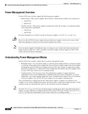
...the power from all installed power supplies to support the power requirements of the switch configuration. Understanding How Power Management Works on the Catalyst 4500 Series Switches Chapter 28 Power Management Power Management Overview Catalyst 4500 series switches support the following ...supply, even for the power requirements of the Catalyst 4500 series switching modules. 28-2 Catalyst 4500 Series, Catalyst 2948G, Catalyst 2980G Switches Software Configuration Guide-Release 8.1 78-15486-01 For example, if your switch configuration requires more modules might shut down. Combined ...
...the power from all installed power supplies to support the power requirements of the switch configuration. Understanding How Power Management Works on the Catalyst 4500 Series Switches Chapter 28 Power Management Power Management Overview Catalyst 4500 series switches support the following ...supply, even for the power requirements of the Catalyst 4500 series switching modules. 28-2 Catalyst 4500 Series, Catalyst 2948G, Catalyst 2980G Switches Software Configuration Guide-Release 8.1 78-15486-01 For example, if your switch configuration requires more modules might shut down. Combined ...
Software Guide
Page 423
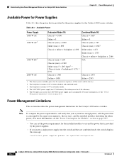
... powered devices. • See Table 28-1 on page 28-5. • When you use power supplies with different types or wattages, the switch uses only one power supply is installed, your switch to combined mode and only one power supply is set the power budget to accommodate the chassis and inline power requirements when... supply bay (PS2). Caution Do not use the 1400 W DC power supply with any other power supply, even for each power supply. 78-15486-01 Catalyst 4500 Series, Catalyst 2948G, Catalyst 2980G Switches Software Configuration Guide-Release 8.1 28-3
... powered devices. • See Table 28-1 on page 28-5. • When you use power supplies with different types or wattages, the switch uses only one power supply is installed, your switch to combined mode and only one power supply is set the power budget to accommodate the chassis and inline power requirements when... supply bay (PS2). Caution Do not use the 1400 W DC power supply with any other power supply, even for each power supply. 78-15486-01 Catalyst 4500 Series, Catalyst 2948G, Catalyst 2980G Switches Software Configuration Guide-Release 8.1 28-3
Software Guide
Page 424
... switch displays this message: Insufficient power supplies present for the installed modules to exceed the power that is provided by the power supplies for the 1400 W DC power supply and is provided by the supervisor engine(s), the fan trays, and the installed ...the power supplies. • If you insert a single power supply into the switch and then set the power requirements for specified configuration. 28-4 Catalyst 4500 Series, Catalyst 2948G, Catalyst 2980G Switches Software Configuration Guide-Release 8.1 78-15486-01 For more information, see the "Power Management Limitations"...
... switch displays this message: Insufficient power supplies present for the installed modules to exceed the power that is provided by the power supplies for the 1400 W DC power supply and is provided by the supervisor engine(s), the fan trays, and the installed ...the power supplies. • If you insert a single power supply into the switch and then set the power requirements for specified configuration. 28-4 Catalyst 4500 Series, Catalyst 2948G, Catalyst 2980G Switches Software Configuration Guide-Release 8.1 78-15486-01 For more information, see the "Power Management Limitations"...

Software Guide
Page 425
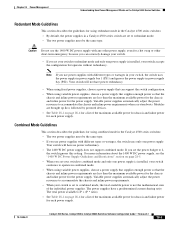
If you install two power supplies in reset mode. • If too many powered devices are drawing power from the DC input. • The 1400 W DC power supply does not support combined mode. The inline power is working properly. 78-15486-01 Catalyst 4500 Series, Catalyst 2948G, Catalyst 2980G Switches Software Configuration Guide-Release 8.1 28-5 The DC...
If you install two power supplies in reset mode. • If too many powered devices are drawing power from the DC input. • The 1400 W DC power supply does not support combined mode. The inline power is working properly. 78-15486-01 Catalyst 4500 Series, Catalyst 2948G, Catalyst 2980G Switches Software Configuration Guide-Release 8.1 28-5 The DC...

Software Guide
Page 426
... may consist of power supplies. For more information, refer to use them without carefully considering the power usage of available power. 28-6 Catalyst 4500 Series, Catalyst 2948G, Catalyst 2980G Switches Software Configuration Guide-Release 8.1 78-15486-01 In those configurations, redundancy requires three power supplies. The total load for the modules, the supervisor engine,... to operate in 2+1 redundancy mode (the default mode), there is in 1+1 redundancy mode (one primary plus one redundant power supply). An attempt to the Catalyst 4000 Series Switch Installation Guide.
... may consist of power supplies. For more information, refer to use them without carefully considering the power usage of available power. 28-6 Catalyst 4500 Series, Catalyst 2948G, Catalyst 2980G Switches Software Configuration Guide-Release 8.1 78-15486-01 In those configurations, redundancy requires three power supplies. The total load for the modules, the supervisor engine,... to operate in 2+1 redundancy mode (the default mode), there is in 1+1 redundancy mode (one primary plus one redundant power supply). An attempt to the Catalyst 4000 Series Switch Installation Guide.

Software Guide
Page 427
... This section describes the guidelines and restrictions for the Catalyst 4006 switch. however, the module is not shown in the show module command output, because the system considers it is installed in the Catalyst 4006 switch: • To compute the power requirements and verify...each module in the chassis than the single power supply provides, the switch places the newly inserted module into reset mode. 78-15486-01 Catalyst 4500 Series, Catalyst 2948G, Catalyst 2980G Switches Software Configuration Guide-Release 8.1 28-7 See the "Power Consumption for Modules" section on...
... This section describes the guidelines and restrictions for the Catalyst 4006 switch. however, the module is not shown in the show module command output, because the system considers it is installed in the Catalyst 4006 switch: • To compute the power requirements and verify...each module in the chassis than the single power supply provides, the switch places the newly inserted module into reset mode. 78-15486-01 Catalyst 4500 Series, Catalyst 2948G, Catalyst 2980G Switches Software Configuration Guide-Release 8.1 28-7 See the "Power Consumption for Modules" section on...