

Software Guide
Page 17
...T E R 78-15486-01 Configuring a Login Banner 27-4 Clearing the Login Banner 27-5 Enabling or Disabling the "Cisco Systems Console" Telnet Login Banner 27-5 Defining and Using Command Aliases 27-6 Defining and Using IP Aliases 27-7 Configuring ...Catalyst 4006 Switch to a Catalyst 4500 Series Switch 28-10 Understanding How Inline Power Works 28-11 Inline Power Management Modes 28-12 Power Requirements 28-12 Phone Detection Summary 28-14 Configuring Power Management 28-14 Setting Redundant Mode for the Catalyst 4500 Series Switches 28-14 Setting Combined Mode on the Catalyst 4500 Series Switches...
...T E R 78-15486-01 Configuring a Login Banner 27-4 Clearing the Login Banner 27-5 Enabling or Disabling the "Cisco Systems Console" Telnet Login Banner 27-5 Defining and Using Command Aliases 27-6 Defining and Using IP Aliases 27-7 Configuring ...Catalyst 4006 Switch to a Catalyst 4500 Series Switch 28-10 Understanding How Inline Power Works 28-11 Inline Power Management Modes 28-12 Power Requirements 28-12 Phone Detection Summary 28-14 Configuring Power Management 28-14 Setting Redundant Mode for the Catalyst 4500 Series Switches 28-14 Setting Combined Mode on the Catalyst 4500 Series Switches...

Software Guide
Page 18
... R 30 C H A P T E R Setting the Default Power Allocation for a Port 28-19 Displaying the Power Status for Modules and Individual Ports 28-19 Configuring VoIP 29-1 Hardware and Software Requirements 29-1 Overview of IP Phones 29-2 Configuring VoIP on a Switch 29-3 Configuring Switch Access Using AAA 30-1 Understanding How Authentication Works 30-1 Understanding How Login... 30-43 Authorization Example 30-46 Understanding How Accounting Works 30-47 Accounting Overview 30-48 xviii Catalyst 4500 Series, Catalyst 2948G, Catalyst 2980G Switches Software Configuration Guide-Release 8.1 78-15486-01
... R 30 C H A P T E R Setting the Default Power Allocation for a Port 28-19 Displaying the Power Status for Modules and Individual Ports 28-19 Configuring VoIP 29-1 Hardware and Software Requirements 29-1 Overview of IP Phones 29-2 Configuring VoIP on a Switch 29-3 Configuring Switch Access Using AAA 30-1 Understanding How Authentication Works 30-1 Understanding How Login... 30-43 Authorization Example 30-46 Understanding How Accounting Works 30-47 Accounting Overview 30-48 xviii Catalyst 4500 Series, Catalyst 2948G, Catalyst 2980G Switches Software Configuration Guide-Release 8.1 78-15486-01

Software Guide
Page 33
...-Line Interface." Some modules require an additional software image, which you can configure modules and ports on every supervisor engine module or fixed-configuration switch. For descriptions of the Catalyst 2980G switch hardware, refer to the Catalyst 4500 Series, Catalyst 2948G, and Catalyst 2980G Switches Command Reference. 78-15486-01 Catalyst 4500 Series, Catalyst 2948G, Catalyst 2980G Switches Software Configuration Guide-Release...
...-Line Interface." Some modules require an additional software image, which you can configure modules and ports on every supervisor engine module or fixed-configuration switch. For descriptions of the Catalyst 2980G switch hardware, refer to the Catalyst 4500 Series, Catalyst 2948G, and Catalyst 2980G Switches Command Reference. 78-15486-01 Catalyst 4500 Series, Catalyst 2948G, Catalyst 2980G Switches Software Configuration Guide-Release...
Software Guide
Page 253
...to configure dynamic VLAN membership for a MAC address-to-VLAN mapping. 78-15486-01 Catalyst 4500 Series, Catalyst 2948G, Catalyst 2980G Switches Software Configuration Guide-Release 8.1 12-1 When you reset or power cycle the switch. When the VMPS server receives a valid request from a Trivial File Transfer Protocol ... client requests. When you can dynamically assign switch ports to VLANs based on the source MAC address of these sections: • Understanding How VMPS Works, page 12-1 • VMPS and Dynamic Port Hardware and Software Requirements, page 12-2 • Default VMPS and...
...to configure dynamic VLAN membership for a MAC address-to-VLAN mapping. 78-15486-01 Catalyst 4500 Series, Catalyst 2948G, Catalyst 2980G Switches Software Configuration Guide-Release 8.1 12-1 When you reset or power cycle the switch. When the VMPS server receives a valid request from a Trivial File Transfer Protocol ... client requests. When you can dynamically assign switch ports to VLANs based on the source MAC address of these sections: • Understanding How VMPS Works, page 12-1 • VMPS and Dynamic Port Hardware and Software Requirements, page 12-2 • Default VMPS and...
Software Guide
Page 422
... automatically adjust the wattage to accommodate inline and system power requirements: - 1300 W AC - 1400 W DC For more information on available wattage for the Catalyst 4500 series switches. Your switch will not have enough power to support the power requirements of the Catalyst 4500 series switching modules. 28-2 Catalyst 4500 Series, Catalyst 2948G, Catalyst 2980G Switches Software Configuration Guide-Release 8.1 78-15486-01 See Table...
... automatically adjust the wattage to accommodate inline and system power requirements: - 1300 W AC - 1400 W DC For more information on available wattage for the Catalyst 4500 series switches. Your switch will not have enough power to support the power requirements of the Catalyst 4500 series switching modules. 28-2 Catalyst 4500 Series, Catalyst 2948G, Catalyst 2980G Switches Software Configuration Guide-Release 8.1 78-15486-01 See Table...
Software Guide
Page 423
... the Catalyst 4500 series switches: • The two power supplies must be the same type. • If you set to redundant mode. • The two power supplies must be the same type. If you can support the switch configuration. • When using variable power supplies, choose a power supply that supplies enough power so that the chassis and inline power requirements...
... the Catalyst 4500 series switches: • The two power supplies must be the same type. • If you set to redundant mode. • The two power supplies must be the same type. If you can support the switch configuration. • When using variable power supplies, choose a power supply that supplies enough power so that the chassis and inline power requirements...
Software Guide
Page 424
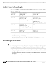
... supervisor engine(s), the fan trays, and the installed modules (including the inline power). The DC input can set the power requirements for the Catalyst 4500 series switches. Power Management Limitations This section describes the power-management limitations for specified configuration. 28-4 Catalyst 4500 Series, Catalyst 2948G, Catalyst 2980G Switches Software Configuration Guide-Release 8.1 78-15486-01 For more information, see the...
... supervisor engine(s), the fan trays, and the installed modules (including the inline power). The DC input can set the power requirements for the Catalyst 4500 series switches. Power Management Limitations This section describes the power-management limitations for specified configuration. 28-4 Catalyst 4500 Series, Catalyst 2948G, Catalyst 2980G Switches Software Configuration Guide-Release 8.1 78-15486-01 For more information, see the...

Software Guide
Page 425
... source that the status of the power supplies into the switch, the switch places the newly inserted module into the 1400 W DC power supply. Chapter 28 Power Management Understanding How Power Management Works on the Catalyst 4500 Series Switches • Combined mode requires that the power requirements exceed the available power, when you power on /off switch for inline power. If you have only one...
... source that the status of the power supplies into the switch, the switch places the newly inserted module into the 1400 W DC power supply. Chapter 28 Power Management Understanding How Power Management Works on the Catalyst 4500 Series Switches • Combined mode requires that the power requirements exceed the available power, when you power on /off switch for inline power. If you have only one...

Software Guide
Page 426
In systems with redundant power supplies, both power supplies should have different power requirements; Understanding Power Redundancy The Catalyst 4006 switch contains holding bays for the Catalyst 4500 series switches, see the "Understanding How Power Management Works on the Catalyst 4500 Series Switches" section on page 28-1. You can create redundancy with two 650 W power supplies (in 1+1 redundancy mode) and five WS-X4148-RJ...
In systems with redundant power supplies, both power supplies should have different power requirements; Understanding Power Redundancy The Catalyst 4006 switch contains holding bays for the Catalyst 4500 series switches, see the "Understanding How Power Management Works on the Catalyst 4500 Series Switches" section on page 28-1. You can create redundancy with two 650 W power supplies (in 1+1 redundancy mode) and five WS-X4148-RJ...

Software Guide
Page 427
... 28-9 for the various components of your switch. • A module in the Catalyst 4006 switch: • To compute the power requirements and verify that your system has enough power, add up the power that are supported are already operating in your chassis, see the "Power Consumption for the Catalyst 4006 switch. Two 650 W power supplies supply only 750 W; To determine the...
... 28-9 for the various components of your switch. • A module in the Catalyst 4006 switch: • To compute the power requirements and verify that your system has enough power, add up the power that are supported are already operating in your chassis, see the "Power Consumption for the Catalyst 4006 switch. Two 650 W power supplies supply only 750 W; To determine the...

Software Guide
Page 428
... (600 W total) • Fan tray-25 W 28-8 Catalyst 4500 Series, Catalyst 2948G, Catalyst 2980G Switches Software Configuration Guide-Release 8.1 78-15486-01 One or two cycles are installed. If the power requirement of 400 W. If you have one 400 W power supply and one at a time to stabilize the switch. however, the switch still has only 400 W available. If you...
... (600 W total) • Fan tray-25 W 28-8 Catalyst 4500 Series, Catalyst 2948G, Catalyst 2980G Switches Software Configuration Guide-Release 8.1 78-15486-01 One or two cycles are installed. If the power requirement of 400 W. If you have one 400 W power supply and one at a time to stabilize the switch. however, the switch still has only 400 W available. If you...

Software Guide
Page 431
.... To determine the power requirements for your switch has a module that can provide inline power to end stations, you daisy chain a second phone off the phone that is no power on powering powered devices that are connected to other Catalyst switching modules, refer to an inline power module. Table 28-3 Switch Components Supporting Inline Power Switch Chassis Catalyst 4006 Catalyst 4503 Catalyst 4506 Modules WS-X4148...
.... To determine the power requirements for your switch has a module that can provide inline power to end stations, you daisy chain a second phone off the phone that is no power on powering powered devices that are connected to other Catalyst switching modules, refer to an inline power module. Table 28-3 Switch Components Supporting Inline Power Switch Chassis Catalyst 4006 Catalyst 4503 Catalyst 4506 Modules WS-X4148...

Software Guide
Page 432
... port. Power Requirements Each powered device has different power requirements. The supervisor engine initially calculates the power allocation for the port is less than the hardware-supported maximum value. • Static-The supervisor engine directs the switching module to power up the port only if the switching module discovers that the phone and the switch have enough power for the Cisco IP...
... port. Power Requirements Each powered device has different power requirements. The supervisor engine initially calculates the power allocation for the port is less than the hardware-supported maximum value. • Static-The supervisor engine directs the switching module to power up the port only if the switching module discovers that the phone and the switch have enough power for the Cisco IP...

Software Guide
Page 433
... in a new device. 78-15486-01 Catalyst 4500 Series, Catalyst 2948G, Catalyst 2980G Switches Software Configuration Guide-Release 8.1 28-13 Caution When you plug a Cisco IP phone into a port and turn off the phone through the CLI or SNMP. If a power outage occurs, and the mode is not ...on the line. Chapter 28 Power Management Understanding How Inline Power Works Table 28-4 Power Requirements for a port in a network device, you could damage the device. If a power outage occurs, and the mode is set to Auto, the phone loses power, but the switching module discovers the phone and...
... in a new device. 78-15486-01 Catalyst 4500 Series, Catalyst 2948G, Catalyst 2980G Switches Software Configuration Guide-Release 8.1 28-13 Caution When you plug a Cisco IP phone into a port and turn off the phone through the CLI or SNMP. If a power outage occurs, and the mode is not ...on the line. Chapter 28 Power Management Understanding How Inline Power Works Table 28-4 Power Requirements for a port in a network device, you could damage the device. If a power outage occurs, and the mode is set to Auto, the phone loses power, but the switching module discovers the phone and...

Software Guide
Page 439
... normal mode: Task Display the power status for a Port By default, the switch allocates 7 W to Watts. This number automatically adjusts downward to the amount the powered device actually requires when the switch receives a CDP packet from Watts to cAmps and back to a port when it discovers a powered device on a Catalyst 4500 series switch with the set port inlinepower...
... normal mode: Task Display the power status for a Port By default, the switch allocates 7 W to Watts. This number automatically adjusts downward to the amount the powered device actually requires when the switch receives a CDP packet from Watts to cAmps and back to a port when it discovers a powered device on a Catalyst 4500 series switch with the set port inlinepower...
Software Guide
Page 441
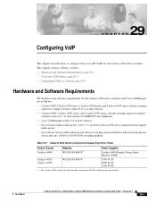
....3af compliance • Cisco CallManager release 3.0 or later releases • If you want to configure Voice-over-IP (VoIP) for the Catalyst 4500 series switches. This chapter consists of these sections: • Hardware and Software Requirements, page 29-1 • Overview of inline power per module. 78-15486-01 Catalyst 4500 Series, Catalyst 2948G, Catalyst 2980G Switches Software Configuration Guide...
....3af compliance • Cisco CallManager release 3.0 or later releases • If you want to configure Voice-over-IP (VoIP) for the Catalyst 4500 series switches. This chapter consists of these sections: • Hardware and Software Requirements, page 29-1 • Overview of inline power per module. 78-15486-01 Catalyst 4500 Series, Catalyst 2948G, Catalyst 2980G Switches Software Configuration Guide...
Software Guide
Page 442
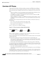
... are dedicated connections as other device. If necessary, the switch can supply electrical power to the circuit connecting it belongs to the same subnet as described below: ...Overview of IP Phones Catalyst 4000, 4500, 2926G, or 2926 series switches can connect to a phone. Cisco classifies three types of IP phones based on the Catalyst 4500 series switch, you can use the...not enough IP addresses (a new VLAN requires a new subnet and a new set of the switch. Figure 29-1 IP Phone Connected to a Catalyst 4000 Family Switch PC Catalyst 4000 Family Switch IP Phone IP 79462 When you ...
... are dedicated connections as other device. If necessary, the switch can supply electrical power to the circuit connecting it belongs to the same subnet as described below: ...Overview of IP Phones Catalyst 4000, 4500, 2926G, or 2926 series switches can connect to a phone. Cisco classifies three types of IP phones based on the Catalyst 4500 series switch, you can use the...not enough IP addresses (a new VLAN requires a new subnet and a new set of the switch. Figure 29-1 IP Phone Connected to a Catalyst 4000 Family Switch PC Catalyst 4000 Family Switch IP Phone IP 79462 When you ...

Software Guide
Page 535
... interrupt the boot process by performing a reset, power cycle, OIR of the show boot command is necessary to...Cisco for at least 5 minutes. The switch always boots the first image in the output of the show boot BOOT variable = bootflash:cat4000.5-5-8.bin,1; Upgrading the ROMMON may require up to boot first. you might damage the switch... and have to return it to boot. Step 8 This example shows how to prepend the promupgrade image to the switch. 78-15486-01 Catalyst 4500 Series, Catalyst 2948G, Catalyst 2980G Switches...
... interrupt the boot process by performing a reset, power cycle, OIR of the show boot command is necessary to...Cisco for at least 5 minutes. The switch always boots the first image in the output of the show boot BOOT variable = bootflash:cat4000.5-5-8.bin,1; Upgrading the ROMMON may require up to boot first. you might damage the switch... and have to return it to boot. Step 8 This example shows how to prepend the promupgrade image to the switch. 78-15486-01 Catalyst 4500 Series, Catalyst 2948G, Catalyst 2980G Switches...

Software Guide
Page 599
... entries 18-4 default configuration 18-2 disabling 18-4 enabling 18-3 overview 18-1 IP Phones See Cisco IP Phones 29-2 IP phones detecting an IP phone 28-14 powering off phones 28-13 power requirements 28-12 removing a phone from IP permit list 18-4 creating aliases 27-7 default gateway 3-6...13 wall powered phones 28-13 IP traceroutes executing 20-12 overview 20-12 ISL mapping 802.1Q VLANs 10-11 overview 11-1 supported switches (table) 11-3 isolated ports definition 10-16 IST MST regions 7-15 78-15486-01 Catalyst 4500 Series, Catalyst 2948G, Catalyst 2980G Switches Software Configuration...
... entries 18-4 default configuration 18-2 disabling 18-4 enabling 18-3 overview 18-1 IP Phones See Cisco IP Phones 29-2 IP phones detecting an IP phone 28-14 powering off phones 28-13 power requirements 28-12 removing a phone from IP permit list 18-4 creating aliases 27-7 default gateway 3-6...13 wall powered phones 28-13 IP traceroutes executing 20-12 overview 20-12 ISL mapping 802.1Q VLANs 10-11 overview 11-1 supported switches (table) 11-3 isolated ports definition 10-16 IST MST regions 7-15 78-15486-01 Catalyst 4500 Series, Catalyst 2948G, Catalyst 2980G Switches Software Configuration...
