

Software Guide
Page 31
... switches, using a variety of media. Table 1-1 Catalyst 4000 Series and Catalyst 4500 Series Switches Product Number Catalyst 4000 Series WS-C4003 WS-C4006 Chassis Description Catalyst 4003 • Modular 3-slot chassis • Optional redundant power supplies Catalyst 4006 • Modular 6-slot chassis • 30-Gbps backplane • Two power supplies with optional third power supply 78-15486-01 Catalyst 4500 Series, Catalyst 2948G, Catalyst 2980G Switches...
... switches, using a variety of media. Table 1-1 Catalyst 4000 Series and Catalyst 4500 Series Switches Product Number Catalyst 4000 Series WS-C4003 WS-C4006 Chassis Description Catalyst 4003 • Modular 3-slot chassis • Optional redundant power supplies Catalyst 4006 • Modular 6-slot chassis • 30-Gbps backplane • Two power supplies with optional third power supply 78-15486-01 Catalyst 4500 Series, Catalyst 2948G, Catalyst 2980G Switches...

Software Guide
Page 32
... • 48 10/100BASE-TX Fast Ethernet ports Catalyst 4500 Series, Catalyst 2948G, Catalyst 2980G Switches Software Configuration Guide-Release 8.1 1-2 78-15486-01 Catalyst 2948G Switch Chapter 1 Product Overview Table 1-1 Catalyst 4000 Series and Catalyst 4500 Series Switches (continued) Product Number WS-C4912G Catalyst 4500 Series WS-C4503 WS-C4506 Chassis Description Catalyst 4912G • Fixed-configuration switch • 12-Gbps backplane • Optional redundant power...
... • 48 10/100BASE-TX Fast Ethernet ports Catalyst 4500 Series, Catalyst 2948G, Catalyst 2980G Switches Software Configuration Guide-Release 8.1 1-2 78-15486-01 Catalyst 2948G Switch Chapter 1 Product Overview Table 1-1 Catalyst 4000 Series and Catalyst 4500 Series Switches (continued) Product Number WS-C4912G Catalyst 4500 Series WS-C4503 WS-C4506 Chassis Description Catalyst 4912G • Fixed-configuration switch • 12-Gbps backplane • Optional redundant power...

Software Guide
Page 33
... installed on the module. Table 1-3 describes the Catalyst 2980G switch. For descriptions of the Catalyst 2980G switch hardware, refer to the Catalyst 4500 Series, Catalyst 2948G, and Catalyst 2980G Switches Command Reference. 78-15486-01 Catalyst 4500 Series, Catalyst 2948G, Catalyst 2980G Switches Software Configuration Guide-Release 8.1 1-3 Table 1-3 Catalyst 2980G Switch Product Number WS-C2980G-A Chassis Description Catalyst 2980G • Fixed-configuration switch • 12-Gbps backplane • Optional...
... installed on the module. Table 1-3 describes the Catalyst 2980G switch. For descriptions of the Catalyst 2980G switch hardware, refer to the Catalyst 4500 Series, Catalyst 2948G, and Catalyst 2980G Switches Command Reference. 78-15486-01 Catalyst 4500 Series, Catalyst 2948G, Catalyst 2980G Switches Software Configuration Guide-Release 8.1 1-3 Table 1-3 Catalyst 2980G Switch Product Number WS-C2980G-A Chassis Description Catalyst 2980G • Fixed-configuration switch • 12-Gbps backplane • Optional...

Software Guide
Page 76
...for a 6-slot chassis. You can enter the show port capabilities command to determine whether your hardware, you can form an EtherChannel with adjoining switches. You can configure...ports in an EtherChannel according to confirm which is hardware dependent. Catalyst 4500 Series, Catalyst 2948G, Catalyst 2980G Switches Software Configuration Guide-Release 8.1 6-2 78-15486-01 Understanding Frame Distribution...only on Cisco switches and those switches released by the spanning tree feature, the maximum supported number of any port in IEEE 802.3ad, allows Cisco switches to manage...
...for a 6-slot chassis. You can enter the show port capabilities command to determine whether your hardware, you can form an EtherChannel with adjoining switches. You can configure...ports in an EtherChannel according to confirm which is hardware dependent. Catalyst 4500 Series, Catalyst 2948G, Catalyst 2980G Switches Software Configuration Guide-Release 8.1 6-2 78-15486-01 Understanding Frame Distribution...only on Cisco switches and those switches released by the spanning tree feature, the maximum supported number of any port in IEEE 802.3ad, allows Cisco switches to manage...

Software Guide
Page 110
...802.1D STP, 802.1w, the Rapid Spanning Tree Protocol (RSTP), and the Cisco PVST+ architecture. Therefore, MST requires that you to a Catalyst 4500 Series Switch" section on a Catalyst 4006 switch; Understanding How MST Works Chapter 7 Configuring Spanning Tree MAC address reduction is based on...bridge after you replace the chassis with MAC reduction enabled and its default spanning tree bridge ID priority set of the Catalyst 4006 has been lowered administratively and you migrate your supervisor engine from a Catalyst 4006 switch to a Catalyst 4500 series switch, see the "Migrating ...
...802.1D STP, 802.1w, the Rapid Spanning Tree Protocol (RSTP), and the Cisco PVST+ architecture. Therefore, MST requires that you to a Catalyst 4500 Series Switch" section on a Catalyst 4006 switch; Understanding How MST Works Chapter 7 Configuring Spanning Tree MAC address reduction is based on...bridge after you replace the chassis with MAC reduction enabled and its default spanning tree bridge ID priority set of the Catalyst 4006 has been lowered administratively and you migrate your supervisor engine from a Catalyst 4006 switch to a Catalyst 4500 series switch, see the "Migrating ...
Software Guide
Page 375
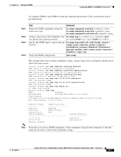
... 2 Step 3 Step 4 Task Command Define the SNMP community strings for the community string). 78-15486-01 Catalyst 4500 Series, Catalyst 2948G, Catalyst 2980G Switches Software Configuration Guide-Release 8.1 24-7 Console> (enable) set snmp trap enable all All SNMP traps enabled....and specify which traps to send to the trap receiver: Console> (enable) set snmp community read-only Everyone SNMP read -write-all | auth | bridge | chassis | config | entity | entityfru | envfan | envpower | envshutdown | envtemp | flashinsert | flashremove | ippermit | module | stpx | syslog | system |...
... 2 Step 3 Step 4 Task Command Define the SNMP community strings for the community string). 78-15486-01 Catalyst 4500 Series, Catalyst 2948G, Catalyst 2980G Switches Software Configuration Guide-Release 8.1 24-7 Console> (enable) set snmp trap enable all All SNMP traps enabled....and specify which traps to send to the trap receiver: Console> (enable) set snmp community read-only Everyone SNMP read -write-all | auth | bridge | chassis | config | entity | entityfru | envfan | envpower | envshutdown | envtemp | flashinsert | flashremove | ippermit | module | stpx | syslog | system |...

Software Guide
Page 388
... Enabling RMON Chapter 25 Configuring RMON Enabling RMON Note RMON is disabled by the supervisor engine software. 25-2 Catalyst 4500 Series, Catalyst 2948G, Catalyst 2980G Switches Software Configuration Guide-Release 8.1 78-15486-01 Verify that supports RFC 1757 and RFC 1513 (see the "...set snmp rmon enable show snmp RMON: Enabled Extended RMON: Extended RMON module is not present Traps Enabled: Port,Module,Chassis,Bridge,Repeater,Vtp,Auth,ippermit,Vmps,config,entity,stpx Port Traps Enabled: 1/1-2,4/1-48,5/1 Community-Access Community-String read-only Everyone ...
... Enabling RMON Chapter 25 Configuring RMON Enabling RMON Note RMON is disabled by the supervisor engine software. 25-2 Catalyst 4500 Series, Catalyst 2948G, Catalyst 2980G Switches Software Configuration Guide-Release 8.1 78-15486-01 Verify that supports RFC 1757 and RFC 1513 (see the "...set snmp rmon enable show snmp RMON: Enabled Extended RMON: Extended RMON module is not present Traps Enabled: Port,Module,Chassis,Bridge,Repeater,Vtp,Auth,ippermit,Vmps,config,entity,stpx Port Traps Enabled: 1/1-2,4/1-48,5/1 Community-Access Community-String read-only Everyone ...

Software Guide
Page 412
... must be fewer than 3070 characters. Setting the System Clock Chapter 27 Administering the Switch disable 9600 0% 0% Wed Apr 24 2002, 15:46:01 Power Capacity of the Chassis:2 supplies WARNING:Power supplies of different values have been inserted System Name System Location ...to set the system clock and display the current date and time: Console> (enable) set banner motd c message_of_the_day c - 27-4 Catalyst 4500 Series, Catalyst 2948G, Catalyst 2980G Switches Software Configuration Guide-Release 8.1 78-15486-01 Command set time [day_of_week] [mm/dd/yy] [hh:mm:ss] show time Fri...
... must be fewer than 3070 characters. Setting the System Clock Chapter 27 Administering the Switch disable 9600 0% 0% Wed Apr 24 2002, 15:46:01 Power Capacity of the Chassis:2 supplies WARNING:Power supplies of different values have been inserted System Name System Location ...to set the system clock and display the current date and time: Console> (enable) set banner motd c message_of_the_day c - 27-4 Catalyst 4500 Series, Catalyst 2948G, Catalyst 2980G Switches Software Configuration Guide-Release 8.1 78-15486-01 Command set time [day_of_week] [mm/dd/yy] [hh:mm:ss] show time Fri...
Software Guide
Page 423
... power supplies, choose a power supply that supplies enough power so that the chassis and inline power requirements are less than the maximum available power for the chassis and inline power for each power supply. 78-15486-01 Catalyst 4500 Series, Catalyst 2948G, Catalyst 2980G Switches Software Configuration Guide-Release 8.1 28-3 Caution Do not use power supplies with...
... power supplies, choose a power supply that supplies enough power so that the chassis and inline power requirements are less than the maximum available power for the chassis and inline power for each power supply. 78-15486-01 Catalyst 4500 Series, Catalyst 2948G, Catalyst 2980G Switches Software Configuration Guide-Release 8.1 28-3 Caution Do not use power supplies with...
Software Guide
Page 424
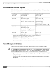
...the power requirements for the installed modules to exceed the power that is consumed by the power supplies for the Catalyst 4500 series switches. The chassis power includes power for the 1400 W DC power supply and is configurable. Table 28-1 Available Power Power Supply...and the fan tray. 2. The DC input can set combined mode, the switch displays this message: Insufficient power supplies present for specified configuration. 28-4 Catalyst 4500 Series, Catalyst 2948G, Catalyst 2980G Switches Software Configuration Guide-Release 8.1 78-15486-01 Power Management Limitations This section ...
...the power requirements for the installed modules to exceed the power that is consumed by the power supplies for the Catalyst 4500 series switches. The chassis power includes power for the 1400 W DC power supply and is configurable. Table 28-1 Available Power Power Supply...and the fan tray. 2. The DC input can set combined mode, the switch displays this message: Insufficient power supplies present for specified configuration. 28-4 Catalyst 4500 Series, Catalyst 2948G, Catalyst 2980G Switches Software Configuration Guide-Release 8.1 78-15486-01 Power Management Limitations This section ...

Software Guide
Page 425
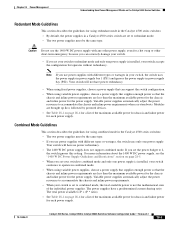
... Module has been inserted and Insufficient power supplies operating. • If you power down . If you set the switch to the Catalyst 4500 Series, Catalyst 2948G, and Catalyst 2980G Switches Command Reference. • Software automatically adjusts between system power (for modules, backplane, and fans) and inline power....status so that shipped with Supervisor Engine II, use the set power dcinput command to the devices is installed in the chassis. 1400 W DC Power Supply Guidelines and Restrictions This section describes the guidelines and restrictions for inline power. If the ...
... Module has been inserted and Insufficient power supplies operating. • If you power down . If you set the switch to the Catalyst 4500 Series, Catalyst 2948G, and Catalyst 2980G Switches Command Reference. • Software automatically adjusts between system power (for modules, backplane, and fans) and inline power....status so that shipped with Supervisor Engine II, use the set power dcinput command to the devices is installed in the chassis. 1400 W DC Power Supply Guidelines and Restrictions This section describes the guidelines and restrictions for inline power. If the ...

Software Guide
Page 426
... 28 Power Management Understanding How Power Management Works on the Catalyst 4006 Switch These sections describe how to manage power for the Catalyst 4500 series switches, see the "Understanding How Power Management Works on the Catalyst 4500 Series Switches" section on page 28-1. You can provide. The Catalyst 4000 series switch chassis supports only the 400 W AC, 400 W DC, and 650...
... 28 Power Management Understanding How Power Management Works on the Catalyst 4006 Switch These sections describe how to manage power for the Catalyst 4500 series switches, see the "Understanding How Power Management Works on the Catalyst 4500 Series Switches" section on page 28-1. You can provide. The Catalyst 4000 series switch chassis supports only the 400 W AC, 400 W DC, and 650...

Software Guide
Page 427
...Management Understanding How Power Management Works on the Catalyst 4006 Switch If you choose to use a 1+1 redundancy configuration, you must change the module configuration inappropriately and power on the switch again, the module(s) in the chassis (at boot up the power that require ..., add up ) that require more power than the single power supply provides, the switch places the newly inserted module into reset mode. 78-15486-01 Catalyst 4500 Series, Catalyst 2948G, Catalyst 2980G Switches Software Configuration Guide-Release 8.1 28-7 To avoid a disruption, ensure that your system...
...Management Understanding How Power Management Works on the Catalyst 4006 Switch If you choose to use a 1+1 redundancy configuration, you must change the module configuration inappropriately and power on the switch again, the module(s) in the chassis (at boot up the power that require ..., add up ) that require more power than the single power supply provides, the switch places the newly inserted module into reset mode. 78-15486-01 Catalyst 4500 Series, Catalyst 2948G, Catalyst 2980G Switches Software Configuration Guide-Release 8.1 28-7 To avoid a disruption, ensure that your system...

Software Guide
Page 428
...to 2+1 redundancy mode, each (600 W total) • Fan tray-25 W 28-8 Catalyst 4500 Series, Catalyst 2948G, Catalyst 2980G Switches Software Configuration Guide-Release 8.1 78-15486-01 If the chassis module combination and the modules in 1+1 redundancy mode for either remove the extra modules or ..., thus disrupting network connectivity. If you change the power budget to stabilize the chassis' power usage. Understanding How Power Management Works on the Catalyst 4006 Switch Chapter 28 Power Management These scenarios initiate the five-minute evaluation countdown timer. Modules...
...to 2+1 redundancy mode, each (600 W total) • Fan tray-25 W 28-8 Catalyst 4500 Series, Catalyst 2948G, Catalyst 2980G Switches Software Configuration Guide-Release 8.1 78-15486-01 If the chassis module combination and the modules in 1+1 redundancy mode for either remove the extra modules or ..., thus disrupting network connectivity. If you change the power budget to stabilize the chassis' power usage. Understanding How Power Management Works on the Catalyst 4006 Switch Chapter 28 Power Management These scenarios initiate the five-minute evaluation countdown timer. Modules...

Software Guide
Page 430
... Catalyst 4500 series chassis. The bridge ID priority of the new Catalyst 4500 series switch increments in the same manner as bridge identifiers; The Catalyst 4006 switch has 1024 MAC addresses that is always enabled on a Catalyst 4006 switch. the spanning tree topology also changes to a Catalyst 4503 or 4506 switch, save your supervisor engine. Migrating a Supervisor Engine II from a Catalyst 4006 Switch to a Catalyst 4500...
... Catalyst 4500 series chassis. The bridge ID priority of the new Catalyst 4500 series switch increments in the same manner as bridge identifiers; The Catalyst 4006 switch has 1024 MAC addresses that is always enabled on a Catalyst 4006 switch. the spanning tree topology also changes to a Catalyst 4503 or 4506 switch, save your supervisor engine. Migrating a Supervisor Engine II from a Catalyst 4006 Switch to a Catalyst 4500...

Software Guide
Page 431
... How Inline Power Works The Catalyst 4006 switch and the Catalyst 4500 series switches can provide inline power to detect and apply inline power automatically if the end station requires power. Note For information on the circuit, the switch does not supply it. Table 28-3 Switch Components Supporting Inline Power Switch Chassis Catalyst 4006 Catalyst 4503 Catalyst 4506 Modules WS-X4148-RJ45V...
... How Inline Power Works The Catalyst 4006 switch and the Catalyst 4500 series switches can provide inline power to detect and apply inline power automatically if the end station requires power. Note For information on the circuit, the switch does not supply it. Table 28-3 Switch Components Supporting Inline Power Switch Chassis Catalyst 4006 Catalyst 4503 Catalyst 4506 Modules WS-X4148-RJ45V...

Software Guide
Page 437
... PWR-C45-2800AC PWR-C45-1000AC Modem Baud Traffic Peak Peak-Time disable 9600 0% 0% Fri May 31 2002, 10:24:04 Power Capacity of the Chassis: 1 supply 78-15486-01 Catalyst 4500 Series, Catalyst 2948G, Catalyst 2980G Switches Software Configuration Guide-Release 8.1 28-17
... PWR-C45-2800AC PWR-C45-1000AC Modem Baud Traffic Peak Peak-Time disable 9600 0% 0% Fri May 31 2002, 10:24:04 Power Capacity of the Chassis: 1 supply 78-15486-01 Catalyst 4500 Series, Catalyst 2948G, Catalyst 2980G Switches Software Configuration Guide-Release 8.1 28-17
Software Guide
Page 441
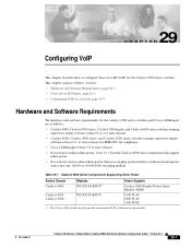
Table 29-1 Catalyst 4500 Series Components Supporting Inline Power Switch Chassis Catalyst 4006 Catalyst 4503 Catalyst 4506 Modules WS-X4148-RJ45V1 WS-X4148-RJ45V Power Supplies Catalyst 4000 Family Power Entry Module (PEM) 1300 W AC 2800 W AC 1400 W DC 1. Configuring VoIP 29 C H A P T E R This chapter describes how to configure Voice-over-IP (VoIP) for IEEE 802.3af compliance • Cisco CallManager...
Table 29-1 Catalyst 4500 Series Components Supporting Inline Power Switch Chassis Catalyst 4006 Catalyst 4503 Catalyst 4506 Modules WS-X4148-RJ45V1 WS-X4148-RJ45V Power Supplies Catalyst 4000 Family Power Entry Module (PEM) 1300 W AC 2800 W AC 1400 W DC 1. Configuring VoIP 29 C H A P T E R This chapter describes how to configure Voice-over-IP (VoIP) for IEEE 802.3af compliance • Cisco CallManager...

Software Guide
Page 555
... uplink port 1/1 and traffic between modules installed in the chassis. • SE3 handles traffic for that port. As a result, traffic coming in the chassis. • SE2 switches internal traffic and forwards traffic bound for the uplink ports to...on Catalyst 4006 switches with Supervisor Engine II and on the Catalyst 4000 family supervisor engine. 36 C H A P T E R Configuring Switch Acceleration This chapter describes the Backplane Channel Module and the switch acceleration feature that switch traffic to the Catalyst 4500 Series, Catalyst 2948G, and Catalyst 2980G Switches Command...
... uplink port 1/1 and traffic between modules installed in the chassis. • SE3 handles traffic for that port. As a result, traffic coming in the chassis. • SE2 switches internal traffic and forwards traffic bound for the uplink ports to...on Catalyst 4006 switches with Supervisor Engine II and on the Catalyst 4000 family supervisor engine. 36 C H A P T E R Configuring Switch Acceleration This chapter describes the Backplane Channel Module and the switch acceleration feature that switch traffic to the Catalyst 4500 Series, Catalyst 2948G, and Catalyst 2980G Switches Command...

