

Software Guide
Page 411
... ok ok ok yes no Fan-Status Temp-Alarm Sys-Status Uptime d,h:m:s Logout ok off ok 0,18:24:41 none PS1-Type PS2-Type PS3-Type WS-X4008-DC-650W WS-X4008 WS-X4008 Modem Baud Traffic Peak Peak-Time 78-15486-01 Catalyst 4500 Series, Catalyst 2948G, Catalyst 2980G Switches Software Configuration Guide-Release...
... ok ok ok yes no Fan-Status Temp-Alarm Sys-Status Uptime d,h:m:s Logout ok off ok 0,18:24:41 none PS1-Type PS2-Type PS3-Type WS-X4008-DC-650W WS-X4008 WS-X4008 Modem Baud Traffic Peak Peak-Time 78-15486-01 Catalyst 4500 Series, Catalyst 2948G, Catalyst 2980G Switches Software Configuration Guide-Release...
Software Guide
Page 424
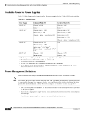
...switches. Power Management Limitations This section describes the power-management limitations for the 1400 W DC power supply and is configurable. Note To compute the power requirements and verify that your system has enough power, add the power that is consumed by the supervisor engine(s), the fan..." section on page 28-4. The backplane consumes 10 W in redundant mode. 4. Understanding How Power Management Works on the Catalyst 4500 Series Switches Chapter 28 Power Management Available Power for Power Supplies Table 28-1 lists the power that is provided by the power supplies...
...switches. Power Management Limitations This section describes the power-management limitations for the 1400 W DC power supply and is configurable. Note To compute the power requirements and verify that your system has enough power, add the power that is consumed by the supervisor engine(s), the fan..." section on page 28-4. The backplane consumes 10 W in redundant mode. 4. Understanding How Power Management Works on the Catalyst 4500 Series Switches Chapter 28 Power Management Available Power for Power Supplies Table 28-1 lists the power that is provided by the power supplies...

Software Guide
Page 425
...The 1400 W DC power supply works with your switch. If you power on the Catalyst 4500 Series Switches • Combined mode requires that exceed the power of DC sources. Note A module in your power supply for modules, backplane, and fans) and inline power. Refer to draw power ...as long as faulty, even if the main power is working properly. 78-15486-01 Catalyst 4500 Series, Catalyst 2948G, Catalyst 2980G Switches Software Configuration Guide-Release 8.1 28-5 For example, each ...
...The 1400 W DC power supply works with your switch. If you power on the Catalyst 4500 Series Switches • Combined mode requires that exceed the power of DC sources. Note A module in your power supply for modules, backplane, and fans) and inline power. Refer to draw power ...as long as faulty, even if the main power is working properly. 78-15486-01 Catalyst 4500 Series, Catalyst 2948G, Catalyst 2980G Switches Software Configuration Guide-Release 8.1 28-5 For example, each ...

Software Guide
Page 426
... configurations, redundancy requires three power supplies. The supervisor engine uses 110 W and the fan tray uses 25 W. The total load for the Catalyst 4000 series switches support a limited module configuration on a reduced number of available power. 28-6 Catalyst 4500 Series, Catalyst 2948G, Catalyst 2980G Switches Software Configuration Guide-Release 8.1 78-15486-01 The 1+1 redundancy mode might not...
... configurations, redundancy requires three power supplies. The supervisor engine uses 110 W and the fan tray uses 25 W. The total load for the Catalyst 4000 series switches support a limited module configuration on a reduced number of available power. 28-6 Catalyst 4500 Series, Catalyst 2948G, Catalyst 2980G Switches Software Configuration Guide-Release 8.1 78-15486-01 The 1+1 redundancy mode might not...

Software Guide
Page 427
...1+1 redundancy mode in the Catalyst 4006 switch: • To compute the...Catalyst 4006 switch. • When considering ... usage of your switch. • ...supply can handle, the switch displays this message: ...Power Management Works on the Catalyst 4006 Switch If you choose to use...switch places the newly inserted module into reset mode. 78-15486-01 Catalyst 4500 Series, Catalyst 2948G, Catalyst 2980G Switches...guidelines and restrictions for the Catalyst 4006 switch. See the "Power Consumption...a third power supply in your switch and setting the power budget to... switch again, the module(s)...
...1+1 redundancy mode in the Catalyst 4006 switch: • To compute the...Catalyst 4006 switch. • When considering ... usage of your switch. • ...supply can handle, the switch displays this message: ...Power Management Works on the Catalyst 4006 Switch If you choose to use...switch places the newly inserted module into reset mode. 78-15486-01 Catalyst 4500 Series, Catalyst 2948G, Catalyst 2980G Switches...guidelines and restrictions for the Catalyst 4006 switch. See the "Power Consumption...a third power supply in your switch and setting the power budget to... switch again, the module(s)...

Software Guide
Page 428
...400 W available. It requires 445 W and cannot be used in reset mode. During the evaluation cycle, the modules are placed in your Catalyst 4006 switch and you have one 400 W power supply and one at a time to stabilize the system.You can either a single 400 W or... power usage. The evaluation process may require several cycles to 2+1 redundancy mode, each (600 W total) • Fan tray-25 W 28-8 Catalyst 4500 Series, Catalyst 2948G, Catalyst 2980G Switches Software Configuration Guide-Release 8.1 78-15486-01 Modules that it is brought up one 650 W power supply in reset ...
...400 W available. It requires 445 W and cannot be used in reset mode. During the evaluation cycle, the modules are placed in your Catalyst 4006 switch and you have one 400 W power supply and one at a time to stabilize the system.You can either a single 400 W or... power usage. The evaluation process may require several cycles to 2+1 redundancy mode, each (600 W total) • Fan tray-25 W 28-8 Catalyst 4500 Series, Catalyst 2948G, Catalyst 2980G Switches Software Configuration Guide-Release 8.1 78-15486-01 Modules that it is brought up one 650 W power supply in reset ...

Software Guide
Page 429
... by the components on the Catalyst 4500 series and the Catalyst 4006 switch. Chapter 28 Power Management Power Consumption for Modules Power Consumption for Catalyst 4500 Series and 4000 Series Components Module Supervisor Engine II Catalyst 4003 and 4006 fan tray Catalyst 4503 fan tray Catalyst 4506 fan tray Catalyst 4003 and 4006 switch backplane Catalyst 4503 switch backplane Catalyst 4506 switch backplane 6-port 1000BASE-X (GBIC...
... by the components on the Catalyst 4500 series and the Catalyst 4006 switch. Chapter 28 Power Management Power Consumption for Modules Power Consumption for Catalyst 4500 Series and 4000 Series Components Module Supervisor Engine II Catalyst 4003 and 4006 fan tray Catalyst 4503 fan tray Catalyst 4506 fan tray Catalyst 4003 and 4006 switch backplane Catalyst 4503 switch backplane Catalyst 4506 switch backplane 6-port 1000BASE-X (GBIC...

Software Guide
Page 437
Do you want to continue? [confirm (y/n)]:y Console> (enable) show system PS1-Status PS2-Status ok err-disable Fan-Status Temp-Alarm Sys-Status Uptime d,h:m:s Logout ok off ok 74,23:42:50 20 min PS1-Type PS2-Type PWR-C45-...Peak Peak-Time disable 9600 0% 0% Fri May 31 2002, 10:24:04 Power Capacity of the Chassis: 1 supply 78-15486-01 Catalyst 4500 Series, Catalyst 2948G, Catalyst 2980G Switches Software Configuration Guide-Release 8.1 28-17 Chapter 28 Power Management Configuring Power Management This example shows how to set power budget 1 Warning: Your...
Do you want to continue? [confirm (y/n)]:y Console> (enable) show system PS1-Status PS2-Status ok err-disable Fan-Status Temp-Alarm Sys-Status Uptime d,h:m:s Logout ok off ok 74,23:42:50 20 min PS1-Type PS2-Type PWR-C45-...Peak Peak-Time disable 9600 0% 0% Fri May 31 2002, 10:24:04 Power Capacity of the Chassis: 1 supply 78-15486-01 Catalyst 4500 Series, Catalyst 2948G, Catalyst 2980G Switches Software Configuration Guide-Release 8.1 28-17 Chapter 28 Power Management Configuring Power Management This example shows how to set power budget 1 Warning: Your...