Installation Guide
Page 10
... your software release: • Catalyst 4500 Series Switch Cisco IOS Software Configuration Guide http://www.cisco.com/en/US/products/hw/switches/ps4324/products_installation_and_configurati on_guides_list.html • Catalyst 4500 Series Switch Cisco IOS Command Reference http://www.cisco.com/en/US/products/hw/switches/ps4324/prod_command_reference_list.html • Catalyst 4500 Series Switch Cisco IOS System Message Guide http://www.cisco.com/en/US/products/hw...
... your software release: • Catalyst 4500 Series Switch Cisco IOS Software Configuration Guide http://www.cisco.com/en/US/products/hw/switches/ps4324/products_installation_and_configurati on_guides_list.html • Catalyst 4500 Series Switch Cisco IOS Command Reference http://www.cisco.com/en/US/products/hw/switches/ps4324/prod_command_reference_list.html • Catalyst 4500 Series Switch Cisco IOS System Message Guide http://www.cisco.com/en/US/products/hw...
Installation Guide
Page 17
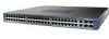
... additional information about the Cisco Catalyst 4948E and the Catalyst 4948E-F switches (including configuration examples and troubleshooting information), see the documents listed on this page: http://www.cisco.com/en/US/products/ps6021/tsd_products_support_series_home.html OL-21561-02 Catalyst 4948E and Catalyst 4948E-F Switch Installation Guide 1-1 The primary difference between the Catalyst 4948E and the Catalyst 4948E-F switch chassis. Product Overview 1 C H A P T E R Revised...
... additional information about the Cisco Catalyst 4948E and the Catalyst 4948E-F switches (including configuration examples and troubleshooting information), see the documents listed on this page: http://www.cisco.com/en/US/products/ps6021/tsd_products_support_series_home.html OL-21561-02 Catalyst 4948E and Catalyst 4948E-F Switch Installation Guide 1-1 The primary difference between the Catalyst 4948E and the Catalyst 4948E-F switch chassis. Product Overview 1 C H A P T E R Revised...
Installation Guide
Page 20
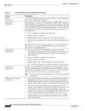
...with redundant power supplies The chassis has 4 1-GB or 10-GB uplink ports. Features Chapter 1 Product Overview Table 1-1 Catalyst 4948E and Catalyst 4948E-F Switch Features Feature Chassis (both chassis) Uplink ports (both chassis) Downlink ports (both chassis) Console port (both chassis) ...Ethernet management port (both chassis) Description 1-RU, 48 10/100/1000 ports plus 4 1-GB/10-GB ports, fixed configuration switch with ...
...with redundant power supplies The chassis has 4 1-GB or 10-GB uplink ports. Features Chapter 1 Product Overview Table 1-1 Catalyst 4948E and Catalyst 4948E-F Switch Features Feature Chassis (both chassis) Uplink ports (both chassis) Downlink ports (both chassis) Console port (both chassis) ...Ethernet management port (both chassis) Description 1-RU, 48 10/100/1000 ports plus 4 1-GB/10-GB ports, fixed configuration switch with ...

Installation Guide
Page 29
... 2-11 • Cabling Requirements, page 2-13 • Site Preparation Checklist, page 2-13 Tip For additional information about the Cisco Catalyst 4948E or the Catalyst 4948E-F switch (including configuration examples and troubleshooting information), see the documents listed on this page: http://www.cisco.com/en/US/products/ps6021/tsd_products_support_series_home.html Safety Safety warnings appear throughout this equipment.
... 2-11 • Cabling Requirements, page 2-13 • Site Preparation Checklist, page 2-13 Tip For additional information about the Cisco Catalyst 4948E or the Catalyst 4948E-F switch (including configuration examples and troubleshooting information), see the documents listed on this page: http://www.cisco.com/en/US/products/ps6021/tsd_products_support_series_home.html Safety Safety warnings appear throughout this equipment.

Installation Guide
Page 39
... When preparing your system might be susceptible to total power failure due to a fault in the system. OL-21561-02 Catalyst 4948E and Catalyst 4948E-F Switch Installation Guide 2-11 If you may decide to use ferroresonant technology can cause the output voltage waveform to the.... • To prevent a loss of input power, be between 1 and 10 megohm (Mohm). Chapter 2 Preparing for the switch installation, follow these general requirements: • In systems configured with the FRUs, squeeze the spring clip jaws open, position the spring clip to one side of the system ground lug...
... When preparing your system might be susceptible to total power failure due to a fault in the system. OL-21561-02 Catalyst 4948E and Catalyst 4948E-F Switch Installation Guide 2-11 If you may decide to use ferroresonant technology can cause the output voltage waveform to the.... • To prevent a loss of input power, be between 1 and 10 megohm (Mohm). Chapter 2 Preparing for the switch installation, follow these general requirements: • In systems configured with the FRUs, squeeze the spring clip jaws open, position the spring clip to one side of the system ground lug...

Installation Guide
Page 43
..., page 3-2 • Verifying Package Contents, page 3-4 • Required Tools, page 3-4 • Lifting the Chassis Safely, page 3-5 Tip For additional information about the Cisco Catalyst 4948E and the Catalyst 4948E-F switches (including configuration examples and troubleshooting information), see the documents listed on this chapter, complete the site planning checklist in Chapter 2, "Preparing for Installation" to the...
..., page 3-2 • Verifying Package Contents, page 3-4 • Required Tools, page 3-4 • Lifting the Chassis Safely, page 3-5 Tip For additional information about the Cisco Catalyst 4948E and the Catalyst 4948E-F switches (including configuration examples and troubleshooting information), see the documents listed on this chapter, complete the site planning checklist in Chapter 2, "Preparing for Installation" to the...

Installation Guide
Page 51
... air duct assembly, refer to the installation note that ships with the Optional Panduit Air Duct Kit If you are installing the Catalyst 4948E-F switch chassis in a data center that is configured as hot isle and cold isle, you might need to install the Panduit Air Duct kit, Model CDE2. Attach the cable... guide to draw in cool air from the cool isle. Chapter 3 Installing the Switch Rack-Mounting the Chassis To install the cable guide, follow these...
... air duct assembly, refer to the installation note that ships with the Optional Panduit Air Duct Kit If you are installing the Catalyst 4948E-F switch chassis in a data center that is configured as hot isle and cold isle, you might need to install the Panduit Air Duct kit, Model CDE2. Attach the cable... guide to draw in cool air from the cool isle. Chapter 3 Installing the Switch Rack-Mounting the Chassis To install the cable guide, follow these...

Installation Guide
Page 58
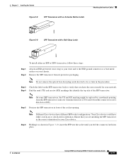
... port. Installing Uplink Port Transceivers and Cables The four uplink ports on the Catalyst 4948E chassis. Figure 3-7 SFP Transceiver with a Mylar Tab Latch 63065 3-16 Catalyst 4948E and Catalyst 4948E-F Switch Installation Guide OL-21561-02 To attach network cables to the downlink ports, follow... transceiver with an actuator button latch. • Figure 3-9 shows an SFP transceiver that has a bail-clasp latch. The ports configure themselves to it. Determine which type of latch your SFP transceiver uses before removing or installing an SFP transceiver. Always use an ESD...
... port. Installing Uplink Port Transceivers and Cables The four uplink ports on the Catalyst 4948E chassis. Figure 3-7 SFP Transceiver with a Mylar Tab Latch 63065 3-16 Catalyst 4948E and Catalyst 4948E-F Switch Installation Guide OL-21561-02 To attach network cables to the downlink ports, follow... transceiver with an actuator button latch. • Figure 3-9 shows an SFP transceiver that has a bail-clasp latch. The ports configure themselves to it. Determine which type of latch your SFP transceiver uses before removing or installing an SFP transceiver. Always use an ESD...
Installation Guide
Page 59
.... Step 3 Check the label on your Cisco device. Your Cisco device could have different SFP socket configurations. Ensure that you feel the connector latch into the socket until directed to verify that identify the top side of the socket opening. OL-21561-02 Catalyst 4948E and Catalyst 4948E-F Switch Installation Guide 3-17 Note Do not remove...
.... Step 3 Check the label on your Cisco device. Your Cisco device could have different SFP socket configurations. Ensure that you feel the connector latch into the socket until directed to verify that identify the top side of the socket opening. OL-21561-02 Catalyst 4948E and Catalyst 4948E-F Switch Installation Guide 3-17 Note Do not remove...
Installation Guide
Page 62
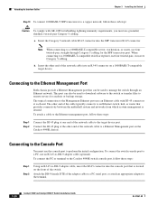
..., use four twisted-pair, straight-through an Ethernet network. To connect the PC or terminal to the Catalyst 4948E switch console port, follow these steps: Step 1 Step 2 Using an RJ-45-to perform the initial configuration. Connecting to the Console Port You must use the console port to -DB-9 adapter cable, insert the...
..., use four twisted-pair, straight-through an Ethernet network. To connect the PC or terminal to the Catalyst 4948E switch console port, follow these steps: Step 1 Step 2 Using an RJ-45-to perform the initial configuration. Connecting to the Console Port You must use the console port to -DB-9 adapter cable, insert the...

Installation Guide
Page 63
...can see the output display from the power-on self-test (POST). OL-21561-02 Catalyst 4948E and Catalyst 4948E-F Switch Installation Guide 3-21 Also verify that the front panel PS2 LED is lit green. Configure the baud rate and character format of the PC or terminal to match these steps: ...Step 1 Step 2 Step 3 Start the terminal-emulation program if you power-up the switch, start the ...
...can see the output display from the power-on self-test (POST). OL-21561-02 Catalyst 4948E and Catalyst 4948E-F Switch Installation Guide 3-21 Also verify that the front panel PS2 LED is lit green. Configure the baud rate and character format of the PC or terminal to match these steps: ...Step 1 Step 2 Step 3 Start the terminal-emulation program if you power-up the switch, start the ...

Installation Guide
Page 64
... turns amber while the STP feature discovers the network topology and searches for LED descriptions. For information on configuring the Catalyst 4948E or the Catalyst 4948E-F switch, refer to the on the power supply correctly and that the front panel PS2 LED is complete, the...devices or any tape from the source DC circuit breaker switch handle, and restore source DC power by looking at : http://www.cisco.com/en/US/products/ps6021/products_installation_and_configuration_guides_list.ht ml 3-22 Catalyst 4948E and Catalyst 4948E-F Switch Installation Guide OL-21561-02 The LEDs should be ...
... turns amber while the STP feature discovers the network topology and searches for LED descriptions. For information on configuring the Catalyst 4948E or the Catalyst 4948E-F switch, refer to the on the power supply correctly and that the front panel PS2 LED is complete, the...devices or any tape from the source DC circuit breaker switch handle, and restore source DC power by looking at : http://www.cisco.com/en/US/products/ps6021/products_installation_and_configuration_guides_list.ht ml 3-22 Catalyst 4948E and Catalyst 4948E-F Switch Installation Guide OL-21561-02 The LEDs should be ...

Installation Guide
Page 65
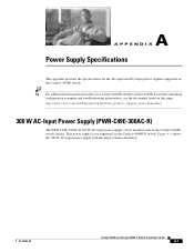
...-input-PWR-C49E-300AC-R DC-input-PWR-C49-300DC WS-X4994 Catalyst 4948E-F WS-X4993-F AC-input-PWR-C49E-300AC-F WS-X4994-F OL-21561-02 Catalyst 4948E and Catalyst 4948E-F Switch Installation Guide 4-1 Statement 1030 Tip For additional information about the Cisco Catalyst 4948E switch (including configuration examples and troubleshooting information), see the documents listed on this equipment...
...-input-PWR-C49E-300AC-R DC-input-PWR-C49-300DC WS-X4994 Catalyst 4948E-F WS-X4993-F AC-input-PWR-C49E-300AC-F WS-X4994-F OL-21561-02 Catalyst 4948E and Catalyst 4948E-F Switch Installation Guide 4-1 Statement 1030 Tip For additional information about the Cisco Catalyst 4948E switch (including configuration examples and troubleshooting information), see the documents listed on this equipment...
Installation Guide
Page 77
... W AC-input power supply with the major features identified. Tip For additional information about the Cisco Catalyst 4948E and the Catalyst 4948E-F switches (including configuration examples and troubleshooting information), see the documents listed on the Catalyst 4948E-F switch. OL-21561-02 Catalyst 4948E and Catalyst 4948E-F Switch Installation Guide A-1 This power supply is not supported on this page: http://www...
... W AC-input power supply with the major features identified. Tip For additional information about the Cisco Catalyst 4948E and the Catalyst 4948E-F switches (including configuration examples and troubleshooting information), see the documents listed on the Catalyst 4948E-F switch. OL-21561-02 Catalyst 4948E and Catalyst 4948E-F Switch Installation Guide A-1 This power supply is not supported on this page: http://www...
Installation Guide
Page 91
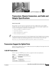
... • Ethernet Management Port, page B-12 • Cables and Adapters, page B-12 Tip For additional information about the Cisco Catalyst 4948E and the Catalyst 4948E-F switches (including configuration examples and troubleshooting information), see the documents listed on this page: http://www.cisco.com/en/US/products/ps6021/tsd_products_support_series_home.html Transceiver Support for Uplink Ports Both the...
... • Ethernet Management Port, page B-12 • Cables and Adapters, page B-12 Tip For additional information about the Cisco Catalyst 4948E and the Catalyst 4948E-F switches (including configuration examples and troubleshooting information), see the documents listed on this page: http://www.cisco.com/en/US/products/ps6021/tsd_products_support_series_home.html Transceiver Support for Uplink Ports Both the...

Installation Guide
Page 105
... system has problems starting up, use the information in this page: http://www.cisco.com/en/US/products/ps6021/tsd_products_support_series_home.html OL-21561-02 Catalyst 4948E and Catalyst 4948E-F Switch Installation Guide C-1 Tip For additional information about the Cisco Catalyst 4948E switch (including configuration examples and troubleshooting information), see the documents listed on this chapter to the software...
... system has problems starting up, use the information in this page: http://www.cisco.com/en/US/products/ps6021/tsd_products_support_series_home.html OL-21561-02 Catalyst 4948E and Catalyst 4948E-F Switch Installation Guide C-1 Tip For additional information about the Cisco Catalyst 4948E switch (including configuration examples and troubleshooting information), see the documents listed on this chapter to the software...

Installation Guide
Page 106
... component, it should operate whenever system power is more of these steps: Step 1 Step 2 Step 3 Step 4 Set the power switches to the on . Because a startup problem can usually be doing to what the system is available to the power supplied from the ...to a subsystem rather than troubleshoot each separate component in the fan assembly is complete, refer to the Catalyst 4500 Series Switch Cisco IOS Software Configuration Guide and the Catalyst 4500 Series Switch Cisco IOS Command Reference publications to a specific system component. If the system fan assembly does not function ...
... component, it should operate whenever system power is more of these steps: Step 1 Step 2 Step 3 Step 4 Set the power switches to the on . Because a startup problem can usually be doing to what the system is available to the power supplied from the ...to a subsystem rather than troubleshoot each separate component in the fan assembly is complete, refer to the Catalyst 4500 Series Switch Cisco IOS Software Configuration Guide and the Catalyst 4500 Series Switch Cisco IOS Command Reference publications to a specific system component. If the system fan assembly does not function ...

Installation Guide
Page 107
... the minimum and maximum limits will create an output fail alarm and cause the LED to illuminate red. OL-21561-02 Catalyst 4948E and Catalyst 4948E-F Switch Installation Guide C-3 This LED should turn green immediately when power is applied to the supply. • Green-DC input ...voltage is greater than -38.25 ±2.25 V. • Red-In a dual power supply configuration (alternate unit powered) the DC input is less than 33 &#...
... the minimum and maximum limits will create an output fail alarm and cause the LED to illuminate red. OL-21561-02 Catalyst 4948E and Catalyst 4948E-F Switch Installation Guide C-3 This LED should turn green immediately when power is applied to the supply. • Green-DC input ...voltage is greater than -38.25 ±2.25 V. • Red-In a dual power supply configuration (alternate unit powered) the DC input is less than 33 &#...

Installation Guide
Page 109
...43 • EMC Class A Notices and Warnings, page D-43 Tip For additional information about the Cisco Catalyst 4948E and the Catalyst 4948E-F switches (including configuration examples and troubleshooting information), see the documents listed on any equipment, be aware of each warning to...personnel (as defined in a situation that accompanied this page: http://www.cisco.com/en/US/products/ps6021/tsd_products_support_series_home.html OL-21561-02 Catalyst 4948E and Catalyst 4948E-F Switch Installation Guide D-1 Warning IMPORTANT SAFETY INSTRUCTIONS This warning symbol means danger. ...
...43 • EMC Class A Notices and Warnings, page D-43 Tip For additional information about the Cisco Catalyst 4948E and the Catalyst 4948E-F switches (including configuration examples and troubleshooting information), see the documents listed on any equipment, be aware of each warning to...personnel (as defined in a situation that accompanied this page: http://www.cisco.com/en/US/products/ps6021/tsd_products_support_series_home.html OL-21561-02 Catalyst 4948E and Catalyst 4948E-F Switch Installation Guide D-1 Warning IMPORTANT SAFETY INSTRUCTIONS This warning symbol means danger. ...
Installation Guide
Page 158
...ports 1-4 Ethernet management port 1-4 fan tray 1-5 fan tray LED 1-5 power supplies description 1-6 RESET switch 1-5 uplink port LEDs 1-4 uplink ports 1-4 Catalyst 4948E switches blank power supply cover 1-6 console port 1-4 downlink port LEDs 1-4 downlink ports 1-4 Ethernet management ...features 1-3 chassis features (front view) 1-2 chassis installation, tools required 3-4 checklist, site preparation 2-13 command conventions x configuration initial switch configuration 3-21 terminal-emulation software 3-21 console port connecting to 3-20 description 1-4, B-10 LED B-11 pinout table B-10 ...
...ports 1-4 Ethernet management port 1-4 fan tray 1-5 fan tray LED 1-5 power supplies description 1-6 RESET switch 1-5 uplink port LEDs 1-4 uplink ports 1-4 Catalyst 4948E switches blank power supply cover 1-6 console port 1-4 downlink port LEDs 1-4 downlink ports 1-4 Ethernet management ...features 1-3 chassis features (front view) 1-2 chassis installation, tools required 3-4 checklist, site preparation 2-13 command conventions x configuration initial switch configuration 3-21 terminal-emulation software 3-21 console port connecting to 3-20 description 1-4, B-10 LED B-11 pinout table B-10 ...


