
Quick Start Guide
Page 2
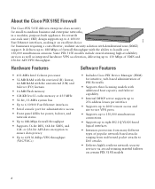
Hardware Features Software Features • 433-MHz Intel Celeron processor • 32-MB RAM with the restricted (R) license; 64-MB RAM with the unrestricted (UR) and failover (FO) licenses • 16-MB Flash memory • 128-KB level 2 cache memory at 433 MHz &#...DES, 168-bit 3DES, and 128- 99550 About the Cisco PIX 515E Firewall The Cisco PIX 515E delivers enterprise-class security for intuitive, web-based administration of PIX Firewalls • Supports three licensing models with additional host capacity and failover capability • Internal DHCP server supports up to 256...
Hardware Features Software Features • 433-MHz Intel Celeron processor • 32-MB RAM with the restricted (R) license; 64-MB RAM with the unrestricted (UR) and failover (FO) licenses • 16-MB Flash memory • 128-KB level 2 cache memory at 433 MHz &#...DES, 168-bit 3DES, and 128- 99550 About the Cisco PIX 515E Firewall The Cisco PIX 515E delivers enterprise-class security for intuitive, web-based administration of PIX Firewalls • Supports three licensing models with additional host capacity and failover capability • Internal DHCP server supports up to 256...

Quick Start Guide
Page 3
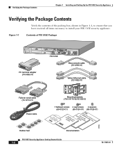
... INTERFACE CARDS WITH POWER APPLIED 100 Mbps Link FDX 100 Mbps Link FDX 10/100 ETHERNET 1 10/100 ETHERNET 0 PIX 515E FAILOVER CONSOLE Blue console cable (72-1259-01) Yellow Ethernet cable (72-1482-01) Failover serial cable (74-1213-01) Power cable Rubber feet Mounting brackets (700-01170-02 AO SSI-3) 7 flathead screws...
... INTERFACE CARDS WITH POWER APPLIED 100 Mbps Link FDX 100 Mbps Link FDX 10/100 ETHERNET 1 10/100 ETHERNET 0 PIX 515E FAILOVER CONSOLE Blue console cable (72-1259-01) Yellow Ethernet cable (72-1482-01) Failover serial cable (74-1213-01) Power cable Rubber feet Mounting brackets (700-01170-02 AO SSI-3) 7 flathead screws...
Quick Start Guide
Page 4
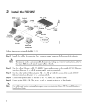
...to a DSL modem, cable modem, or switch. The power switch is also rack-mountable. Connect the power cable to install the PIX 515E: Router Internet Power cable 97998 Step 1 Install the rubber feet onto the five, round, recessed areas on the bottom of the ...of the chassis. 2 Install the PIX 515E DMZ server Switch DMZ PIX 515E Switch Inside Outside Laptop computer Printer Personal computer Follow these steps to the rear of the PIX 515E and a power outlet. For rack-mounting and failover instructions, refer to the Cisco PIX Firewall Hardware Installation Guide. 4 Note...
...to a DSL modem, cable modem, or switch. The power switch is also rack-mountable. Connect the power cable to install the PIX 515E: Router Internet Power cable 97998 Step 1 Install the rubber feet onto the five, round, recessed areas on the bottom of the ...of the chassis. 2 Install the PIX 515E DMZ server Switch DMZ PIX 515E Switch Inside Outside Laptop computer Printer Personal computer Follow these steps to the rear of the PIX 515E and a power outlet. For rack-mounting and failover instructions, refer to the Cisco PIX Firewall Hardware Installation Guide. 4 Note...

Quick Start Guide
Page 32
...-45 connectors and a DB-9 connector. The four-port Ethernet circuit board is required to enter configuration commands. Alternative Ways to Access the PIX 515E You can access the CLI for your computer, and the RJ-45 connector on the other end to the serial port connector on your ...computer. 100 Mbps Link FDX 10/100 ETHERNET 0/0 FAILOVER CONSOLE Console port (RJ-45) RJ-45 to DB-9 serial cable (null-modem) PC terminal adapter DB-9 PIX-515 99547 • If your PIX 515E has a four-port Ethernet circuit board already installed, the Ethernet circuit boards ...
...-45 connectors and a DB-9 connector. The four-port Ethernet circuit board is required to enter configuration commands. Alternative Ways to Access the PIX 515E You can access the CLI for your computer, and the RJ-45 connector on the other end to the serial port connector on your ...computer. 100 Mbps Link FDX 10/100 ETHERNET 0/0 FAILOVER CONSOLE Console port (RJ-45) RJ-45 to DB-9 serial cable (null-modem) PC terminal adapter DB-9 PIX-515 99547 • If your PIX 515E has a four-port Ethernet circuit board already installed, the Ethernet circuit boards ...

Quick Start Guide
Page 33
...the "Installing a Circuit Board in the PIX 515E" section in the Cisco PIX Firewall Hardware Installation Guide. 33 If a four-port FE card is used with the restricted license, only one network interface is activated.) Note If you have a second PIX 515E to bottom so that the top circuit...unit at the rear, the circuit boards are numbered top to use as a failover unit, install the failover feature and cable as described in the "Installing Failover" section in the Cisco PIX Firewall Hardware Installation Guide. PIX-515 Ethernet 5 Ethernet 3 Ethernet 2 Ethernet 4 Ethernet 2 DO NOT INSTALL ...
...the "Installing a Circuit Board in the PIX 515E" section in the Cisco PIX Firewall Hardware Installation Guide. 33 If a four-port FE card is used with the restricted license, only one network interface is activated.) Note If you have a second PIX 515E to bottom so that the top circuit...unit at the rear, the circuit boards are numbered top to use as a failover unit, install the failover feature and cable as described in the "Installing Failover" section in the Cisco PIX Firewall Hardware Installation Guide. PIX-515 Ethernet 5 Ethernet 3 Ethernet 2 Ethernet 4 Ethernet 2 DO NOT INSTALL ...

Quick Start Guide
Page 34
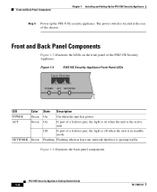
... number of allowed interfaces is off. Step 3 Connect the inside, outside, or perimeter network cables to start the PIX 515E. Check the LEDs POWER ACT NETWORK 97779 Table 1 PIX 515E Front Panel LEDs LED POWER ACT Color Green Green NETWORK Green State Description On On when the unit has power.... On On when the unit is the active unit. Flashing On when at the rear to the interface ports. If failover is present, the ...
... number of allowed interfaces is off. Step 3 Connect the inside, outside, or perimeter network cables to start the PIX 515E. Check the LEDs POWER ACT NETWORK 97779 Table 1 PIX 515E Front Panel LEDs LED POWER ACT Color Green Green NETWORK Green State Description On On when the unit has power.... On On when the unit is the active unit. Flashing On when at the rear to the interface ports. If failover is present, the ...

Quick Start Guide
Page 35
... data exchange where data is using 10-Mbps data exchange. Off If this light is off , the port is transmitted and received simultaneously. PIX-515 97784 100 Mbps LED ACT LED DO NOT INSTALL INTERFACE CARDS WITH POWER APPLIED 100 Mbps LED LINK ACT LED LED USB LINK LED...100 Mbps ACT LINK 100 Mbps ACT LINK 10/100 ETHERNET 1 10/100 ETHERNET 0 FAILOVER USB CONSOLE 10/100BaseTX 10/100BaseTX Console Power switch ETHERNET 1 ETHERNET 0 port (RJ-45) (RJ-45) (RJ-45) Table 2 PIX 515E Real Panel LEDs LED Color 100 Mbps Green ACT Green LINK Green Status Description On 100...
... data exchange where data is using 10-Mbps data exchange. Off If this light is off , the port is transmitted and received simultaneously. PIX-515 97784 100 Mbps LED ACT LED DO NOT INSTALL INTERFACE CARDS WITH POWER APPLIED 100 Mbps LED LINK ACT LED LED USB LINK LED...100 Mbps ACT LINK 100 Mbps ACT LINK 10/100 ETHERNET 1 10/100 ETHERNET 0 FAILOVER USB CONSOLE 10/100BaseTX 10/100BaseTX Console Power switch ETHERNET 1 ETHERNET 0 port (RJ-45) (RJ-45) (RJ-45) Table 2 PIX 515E Real Panel LEDs LED Color 100 Mbps Green ACT Green LINK Green Status Description On 100...
Getting Started Guide
Page 8
... INTERFACE CARDS WITH POWER APPLIED 100 Mbps Link FDX 100 Mbps Link FDX 10/100 ETHERNET 1 10/100 ETHERNET 0 PIX 515E FAILOVER CONSOLE Blue console cable (72-1259-01) Yellow Ethernet cable (72-1482-01) Failover serial cable (74-1213-01) Power cable Mounting brackets (700-01170-02 AO SSI-3) 7 flathead screws 4 cap screws...
... INTERFACE CARDS WITH POWER APPLIED 100 Mbps Link FDX 100 Mbps Link FDX 10/100 ETHERNET 1 10/100 ETHERNET 0 PIX 515E FAILOVER CONSOLE Blue console cable (72-1259-01) Yellow Ethernet cable (72-1482-01) Failover serial cable (74-1213-01) Power cable Mounting brackets (700-01170-02 AO SSI-3) 7 flathead screws 4 cap screws...
Getting Started Guide
Page 10
... interface is the active unit. Front and Back Panel Components Figure 1-3 illustrates the LEDs on when the unit is passing traffic. On If part of a failover pair, the light is in standby mode. Figure 1-4 illustrates the back panel components. Flashing Flashing when at the rear of... NETWORK 97779 LED POWER ACT Color Green Green NETWORK Green State Description On On when the unit has power. Off If part of the chassis. PIX 515E Security Appliance Getting Started Guide 1-4 78-17645-01 Front and Back Panel Components Chapter 1 Installing and Setting Up the...
... interface is the active unit. Front and Back Panel Components Figure 1-3 illustrates the LEDs on when the unit is passing traffic. On If part of a failover pair, the light is in standby mode. Figure 1-4 illustrates the back panel components. Flashing Flashing when at the rear of... NETWORK 97779 LED POWER ACT Color Green Green NETWORK Green State Description On On when the unit has power. Off If part of the chassis. PIX 515E Security Appliance Getting Started Guide 1-4 78-17645-01 Front and Back Panel Components Chapter 1 Installing and Setting Up the...

Getting Started Guide
Page 11
... and Setting Up the PIX 515E Security Appliance Setting Up the Security Appliance Figure 1-4 PIX 515E Security Appliance Back Panel 100 Mbps LED ACT LED CDAORDNSOTWIINTSHTPAOLLWIENRTEARPFPALCIEED 100 Mbps LED LINK ACT LED LED USB LINK LED 100 Mbps ACT LINK 100 Mbps ACT LINK 10/100 ETHERNET 1 10/100 ETHERNET 0 FAILOVER USB CONSOLE 10/100BaseTX...
... and Setting Up the PIX 515E Security Appliance Setting Up the Security Appliance Figure 1-4 PIX 515E Security Appliance Back Panel 100 Mbps LED ACT LED CDAORDNSOTWIINTSHTPAOLLWIENRTEARPFPALCIEED 100 Mbps LED LINK ACT LED LED USB LINK LED 100 Mbps ACT LINK 100 Mbps ACT LINK 10/100 ETHERNET 1 10/100 ETHERNET 0 FAILOVER USB CONSOLE 10/100BaseTX...
