

Installation Guide
Page 2
... longer complying with FCC requirements for a Class B digital device in accordance with Cisco's installation instructions, it was probably caused by the University of California, Berkeley (UCB) as part of UCB's public domain version of their own expense. This equipment has been tested and found to comply with the instruction manual, may cause harmful interference to one of the FCC...
... longer complying with FCC requirements for a Class B digital device in accordance with Cisco's installation instructions, it was probably caused by the University of California, Berkeley (UCB) as part of UCB's public domain version of their own expense. This equipment has been tested and found to comply with the instruction manual, may cause harmful interference to one of the FCC...
Installation Guide
Page 5
... Telephone Devices 4-1 Connecting an ISDN (Digital) Telephone 4-1 Connecting a Self-Powered Digital Telephone 4-2 Connecting a Digital Telephone with an External Power Supply 4-3 Connecting an Analog Telephone Device 4-5 Supplementary Services 4-6 Call Waiting 4-7 Disabling Call Waiting 4-8 Disabling Call Waiting on a Per-Call Basis 4-8 Call Hold and Retrieve 4-8 Call Transfer 4-9 Three-Way Call Conferencing 4-9 Country-Specific Dialing Instructions 4-10 Dialing with INS ISDN Lines for Japan 4-10 Disabling the Pound Key's End...
... Telephone Devices 4-1 Connecting an ISDN (Digital) Telephone 4-1 Connecting a Self-Powered Digital Telephone 4-2 Connecting a Digital Telephone with an External Power Supply 4-3 Connecting an Analog Telephone Device 4-5 Supplementary Services 4-6 Call Waiting 4-7 Disabling Call Waiting 4-8 Disabling Call Waiting on a Per-Call Basis 4-8 Call Hold and Retrieve 4-8 Call Transfer 4-9 Three-Way Call Conferencing 4-9 Country-Specific Dialing Instructions 4-10 Dialing with INS ISDN Lines for Japan 4-10 Disabling the Pound Key's End...

Installation Guide
Page 9
... safety recommendations, connection preparations, and console and auxiliary port cable connection considerations. • Chapter 3, "Installing Your Router," contains instructions on the Cisco Documentation CD-ROM in HTML format (Document Number DOC-782412=). About This Guide ix Audience This publication is also available on how to LAN, WAN, power, and phone connections. The document is designed for a person with your router to cable the router. About This Guide The Cisco 700 Series Router Installation Guide provides hardware installation instructions that guide you through...
... safety recommendations, connection preparations, and console and auxiliary port cable connection considerations. • Chapter 3, "Installing Your Router," contains instructions on the Cisco Documentation CD-ROM in HTML format (Document Number DOC-782412=). About This Guide ix Audience This publication is also available on how to LAN, WAN, power, and phone connections. The document is designed for a person with your router to cable the router. About This Guide The Cisco 700 Series Router Installation Guide provides hardware installation instructions that guide you through...

Installation Guide
Page 10
... to configure the router for Cisco 700 Series Router Software provides the latest information on troubleshooting any problems that is also provided with your router, this information, if you are on the Cisco Documentation CD-ROM and the Cisco Web site. • Cisco 760 Quick Reference Guide and Cisco 770 Quick Reference Guide provide hardware installation instructions, forms to assist you find a solution. • Appendix A, "Specifications," provides the specifications for Cisco 700 series routers, including pinouts for cables used with Cisco 700 series routers. Release...
... to configure the router for Cisco 700 Series Router Software provides the latest information on troubleshooting any problems that is also provided with your router, this information, if you are on the Cisco Documentation CD-ROM and the Cisco Web site. • Cisco 760 Quick Reference Guide and Cisco 770 Quick Reference Guide provide hardware installation instructions, forms to assist you find a solution. • Appendix A, "Specifications," provides the specifications for Cisco 700 series routers, including pinouts for cables used with Cisco 700 series routers. Release...
Installation Guide
Page 17
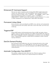
... ISDN connections based on the level of the traffic demanded on any switch type. Triggered RIP incorporates a reliable delivery mechanism to obtain a configuration file from a remote server using Bootstrap Protocol (BOOTP). In Verbose mode, the response is in numbers, such as ISDN. Dial-On-Demand Routing Dial-on-demand routing (DDR) allows the router to remote devices across ISDN BRI lines. In addition, in software Release 4.3.1, a series of TPAD commands have...
... ISDN connections based on the level of the traffic demanded on any switch type. Triggered RIP incorporates a reliable delivery mechanism to obtain a configuration file from a remote server using Bootstrap Protocol (BOOTP). In Verbose mode, the response is in numbers, such as ISDN. Dial-On-Demand Routing Dial-on-demand routing (DDR) allows the router to remote devices across ISDN BRI lines. In addition, in software Release 4.3.1, a series of TPAD commands have...

Installation Guide
Page 19
... time expires, the router checks the remaining time in any profile configured for part of Charge-During Active Call (AOC-D) supplementary service. Data Compression Cisco 700 series routers support data compression using Internet Protocol Control Protocol (IPCP) address negotiation. After they arrive at their destination, the packets are compressed before forwarding the packets to the outside world. Overview 1-5 This feature is available only for NET3 (same as ETSI) switch types...
... time expires, the router checks the remaining time in any profile configured for part of Charge-During Active Call (AOC-D) supplementary service. Data Compression Cisco 700 series routers support data compression using Internet Protocol Control Protocol (IPCP) address negotiation. After they arrive at their destination, the packets are compressed before forwarding the packets to the outside world. Overview 1-5 This feature is available only for NET3 (same as ETSI) switch types...

Installation Guide
Page 34
... U cable (Cisco 772 and Cisco 776 routers only). • One orange ISDN S/T cable (Cisco 771 and Cisco 775 routers only). • One RJ-45-to-RJ-11 adapter. • One blue configuration cable. • One black power supply. • One black power supply cord. • One Cisco 700 Series Router Installation Guide. • One Documentation CD-ROM set. (The Cisco 700 Series Command Reference is on Disk 2 of the CD-ROM set.) • One Cisco 700 Quick Reference Guide. • One Cisco...
... U cable (Cisco 772 and Cisco 776 routers only). • One orange ISDN S/T cable (Cisco 771 and Cisco 775 routers only). • One RJ-45-to-RJ-11 adapter. • One blue configuration cable. • One black power supply. • One black power supply cord. • One Cisco 700 Series Router Installation Guide. • One Documentation CD-ROM set. (The Cisco 700 Series Command Reference is on Disk 2 of the CD-ROM set.) • One Cisco 700 Quick Reference Guide. • One Cisco...

Installation Guide
Page 46
... Series Router Installation Guide Table 3-1 LED RDY NT1 LINE LAN Verifying the Connections Connection Power ISDN U port ISDN U or S/T port Ethernet Normal Pattern On when the router is powered on the LAN for 1 minute after boot. On when connected. Off if there is no traffic on . Once the router is booted, you access a Web page on the LAN LED and blinking the companion RDX and TDX LEDs. The CH2 LED might be because the router or PC is not yet configured...
... Series Router Installation Guide Table 3-1 LED RDY NT1 LINE LAN Verifying the Connections Connection Power ISDN U port ISDN U or S/T port Ethernet Normal Pattern On when the router is powered on the LAN for 1 minute after boot. On when connected. Off if there is no traffic on . Once the router is booted, you access a Web page on the LAN LED and blinking the companion RDX and TDX LEDs. The CH2 LED might be because the router or PC is not yet configured...

Installation Guide
Page 56
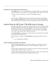
... call waiting service interrupts data transfer when using an analog fax machine connected to the router. (Consult the instructions provided by the manufacturer of the analog telephone ports, you can press the Flash key instead of the telephone, as shown in the following example: **99# When the voice call is completed, call waiting is necessary.) The set callwaiting interface phone1 off Disabling Call...
... call waiting service interrupts data transfer when using an analog fax machine connected to the router. (Consult the instructions provided by the manufacturer of the analog telephone ports, you can press the Flash key instead of the telephone, as shown in the following example: **99# When the voice call is completed, call waiting is necessary.) The set callwaiting interface phone1 off Disabling Call...
Installation Guide
Page 59
... follows: Call Forwarding Unconditional (CFU)-Enables the network to redirect all tones. By default, the router provides all internal tones. This command applies only to software Release 4.0(2) and higher for the dial tone and enter the desired dialing digits, including the pound (#) key. The set internaltones dialtone Call Forwarding in a telephone number, you can configure Cisco 700 series routers to 1TR6 router software. Disabling the Pound Key's End-of...
... follows: Call Forwarding Unconditional (CFU)-Enables the network to redirect all tones. By default, the router provides all internal tones. This command applies only to software Release 4.0(2) and higher for the dial tone and enter the desired dialing digits, including the pound (#) key. The set internaltones dialtone Call Forwarding in a telephone number, you can configure Cisco 700 series routers to 1TR6 router software. Disabling the Pound Key's End-of...

Installation Guide
Page 65
... calls are unsuccessful, check for the following conditions: • A telephone number was incorrectly configured by using the set number command or the Cisco 700 Fast Step Setup application. • The ISDN B channel is under operator control and does not respond to the router. Change the switch type by the ISDN service provider. Confirm the line configuration with the WAN This section describes the problems and solutions commonly found in Cisco 700 series router configurations.
... calls are unsuccessful, check for the following conditions: • A telephone number was incorrectly configured by using the set number command or the Cisco 700 Fast Step Setup application. • The ISDN B channel is under operator control and does not respond to the router. Change the switch type by the ISDN service provider. Confirm the line configuration with the WAN This section describes the problems and solutions commonly found in Cisco 700 series router configurations.
Installation Guide
Page 67
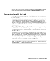
... Descriptions." Troubleshooting Cisco 700 Series Routers 5-5 If it is in the HUB position. If you have problems communicating with a 10BaseT Ethernet LAN device (such as the number configured with the LAN If you are connecting directly to a PC, the switch should be sent to the correct location. If the LED is attempting to establish a connection. If the router calls itself, check that the number configured with the set number command is attempting...
... Descriptions." Troubleshooting Cisco 700 Series Routers 5-5 If it is in the HUB position. If you have problems communicating with a 10BaseT Ethernet LAN device (such as the number configured with the LAN If you are connecting directly to a PC, the switch should be sent to the correct location. If the LED is attempting to establish a connection. If the router calls itself, check that the number configured with the set number command is attempting...
Installation Guide
Page 75
Although this information is supported on lines using Cisco 700 series router manuals to dial outside of user names and secrets (encrypted passwords) between two devices. This security feature is not required to successfully install the router, it might be dialed preceding the telephone number to configure the router. Access code A number that requires an exchange of a specific telephone system, such as a Centrex system. AT commands ATtention commands (used for modem communications) BT British Telecom...
Although this information is supported on lines using Cisco 700 series router manuals to dial outside of user names and secrets (encrypted passwords) between two devices. This security feature is not required to successfully install the router, it might be dialed preceding the telephone number to configure the router. Access code A number that requires an exchange of a specific telephone system, such as a Centrex system. AT commands ATtention commands (used for modem communications) BT British Telecom...
Installation Guide
Page 76
... B channel. This channel combination is the number the router dials to connect to a remote router. Point-to a direct connection between two networks. In an internetwork, the term refers to -Point Protocol (PPP) A direct connection between two devices. PAT Port Address Translation 6-2 Cisco 700 Series Router Installation Guide This is sometimes denoted as a hardware address. EPOS Electronic Point of Sale IE Information Element of user names and clear-text passwords between two nodes; Media Access Control (MAC) address Also known as 2B+D. Internet Protocol (IP) address A network...
... B channel. This channel combination is the number the router dials to connect to a remote router. Point-to a direct connection between two networks. In an internetwork, the term refers to -Point Protocol (PPP) A direct connection between two devices. PAT Port Address Translation 6-2 Cisco 700 Series Router Installation Guide This is sometimes denoted as a hardware address. EPOS Electronic Point of Sale IE Information Element of user names and clear-text passwords between two nodes; Media Access Control (MAC) address Also known as 2B+D. Internet Protocol (IP) address A network...
Installation Guide
Page 87
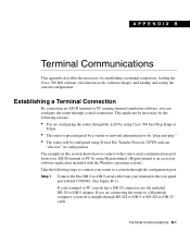
... to connect your router to a console through the LAN by using Cisco 700 Fast Step Setup or Telnet. • The router is preconfigured by using Trivial File Transfer Protocol (TFTP) and can configure the router through RS-422-to-DB-9 or RS-422-to a Macintosh computer, you are configuring the router through the configuration port: Step 1 Connect the blue DB-9-to-DB-9 serial cable from your terminal to the rear-panel port labeled CONFIG. (See...
... to connect your router to a console through the LAN by using Cisco 700 Fast Step Setup or Telnet. • The router is preconfigured by using Trivial File Transfer Protocol (TFTP) and can configure the router through RS-422-to-DB-9 or RS-422-to a Macintosh computer, you are configuring the router through the configuration port: Step 1 Connect the blue DB-9-to-DB-9 serial cable from your terminal to the rear-panel port labeled CONFIG. (See...
Installation Guide
Page 95
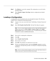
... 5 Step 6 Step 7 Step 8 Select the file containing the configuration. Step 6 Step 7 Press Return to 1 second. The following example loads a configuration using terminal emulation software other than Hyperterminal, it might be necessary to set Flow Control to Line-at-a-Time, and set default command to the file specified in the "Establishing a Terminal Connection" section. If errors occur during the transfer, enter the set Delay Between Lines to 0.5 to execute the...
... 5 Step 6 Step 7 Step 8 Select the file containing the configuration. Step 6 Step 7 Press Return to 1 second. The following example loads a configuration using terminal emulation software other than Hyperterminal, it might be necessary to set Flow Control to Line-at-a-Time, and set default command to the file specified in the "Establishing a Terminal Connection" section. If errors occur during the transfer, enter the set Delay Between Lines to 0.5 to execute the...

Installation Guide
Page 112
... configuration 1-3 Cisco 700 Fast Step 1-1 connecting to Macintosh B-1 DCE device B-2 DMS-100 switch C-13 examples xi line provisioning C-10 to C-13 loading B-9 port B-1 port pinouts A-3 saving B-8 serial port 1-13, B-1 switches C-11 to C-12 terminal connection B-1 TPAD mode B-4 upload command B-8 Web sources xi connecting ISDN line 3-3 power supply 3-9 terminal B-1 to Macintosh B-1 console connecting B-2 port pinouts A-3 Consultative Committee for International Telegraph and Telephone 5-12 See CCITT customer premises equipment 1-2 customer service C-6 Index 2 Cisco 700 Series Router...
... configuration 1-3 Cisco 700 Fast Step 1-1 connecting to Macintosh B-1 DCE device B-2 DMS-100 switch C-13 examples xi line provisioning C-10 to C-13 loading B-9 port B-1 port pinouts A-3 saving B-8 serial port 1-13, B-1 switches C-11 to C-12 terminal connection B-1 TPAD mode B-4 upload command B-8 Web sources xi connecting ISDN line 3-3 power supply 3-9 terminal B-1 to Macintosh B-1 console connecting B-2 port pinouts A-3 Consultative Committee for International Telegraph and Telephone 5-12 See CCITT customer premises equipment 1-2 customer service C-6 Index 2 Cisco 700 Series Router...

Installation Guide
Page 113
... definition 6-2 setting a directory number 5-4 DMS-100 switch description C-3 router configuration requirements router only C-13 with another ISDN device C-13 DMS-100 switch provisioning C-9 documentation xi CD-ROM xi quick reference guide xi release notes x domain name system 1-4 DOV (over ISDN BRI) C-1 DRAM A-1 DTMF command 4-11 troubleshooting 1-12 dynamic host configuration protocol See DHCP E electrostatic discharge (ESD), preventing 2-3 EPOS 1-3, 6-2 EPROM 5-2 error messages ISDN BRI 5-6 to 5-12 LED 5-1 Ethernet cabling 3-1 crossover cable 5-5 HUB/NODE switch 6-4 port pinouts A-2 ports...
... definition 6-2 setting a directory number 5-4 DMS-100 switch description C-3 router configuration requirements router only C-13 with another ISDN device C-13 DMS-100 switch provisioning C-9 documentation xi CD-ROM xi quick reference guide xi release notes x domain name system 1-4 DOV (over ISDN BRI) C-1 DRAM A-1 DTMF command 4-11 troubleshooting 1-12 dynamic host configuration protocol See DHCP E electrostatic discharge (ESD), preventing 2-3 EPOS 1-3, 6-2 EPROM 5-2 error messages ISDN BRI 5-6 to 5-12 LED 5-1 Ethernet cabling 3-1 crossover cable 5-5 HUB/NODE switch 6-4 port pinouts A-2 ports...

Installation Guide
Page 116
... serial configuration 1-13 TCP port numbers A-4 pound key, disabling (Japan) 4-11 power supply A-1 connecting 3-9 connector A-4 pinouts A-4 power-on 5-1 PPP 1-7 authentication protocol 1-9 Bridging Control Protocol (BCP) 1-9 definition 6-2 IPX 1-9 LCP extensions 1-9 Multilink Protocol (MP) 1-9 primary memory A-1 Primary Rate Interface (PRI) See ISDN PRI priority queueing 1-6 private IP network 1-5 processor A-1 provisioning 5ESS Custom switch C-8 DMS-100 switch C-9 ISDN BRI line C-1 to C-4 summaries C-6 to C-10 PSTN 6-3 Q QIC-122 standard 1-5 quick reference guide xi R RAM 5-2, A-1 RD/RDY LED...
... serial configuration 1-13 TCP port numbers A-4 pound key, disabling (Japan) 4-11 power supply A-1 connecting 3-9 connector A-4 pinouts A-4 power-on 5-1 PPP 1-7 authentication protocol 1-9 Bridging Control Protocol (BCP) 1-9 definition 6-2 IPX 1-9 LCP extensions 1-9 Multilink Protocol (MP) 1-9 primary memory A-1 Primary Rate Interface (PRI) See ISDN PRI priority queueing 1-6 private IP network 1-5 processor A-1 provisioning 5ESS Custom switch C-8 DMS-100 switch C-9 ISDN BRI line C-1 to C-4 summaries C-6 to C-10 PSTN 6-3 Q QIC-122 standard 1-5 quick reference guide xi R RAM 5-2, A-1 RD/RDY LED...

Installation Guide
Page 117
... Agent 1-1 self-test 1-11 serial port configuration B-1 TPAD B-4 Service Profile Identifiers See SPIDs service provider 3-11 set directory number command 5-5 set number command 5-4, 5-5 set serial config command B-4 show configuration comman B-4 show version command C-4 signaling message 5-7 Simple Network Management Protocol See SNMP SNMP 1-7 community names 1-7 supported MIBs 1-8 SNMP Management Information Base (MIB) See MIB and SNMP software image B-1 load command B-5 troubleshooting B-7 loading errors B-7 specifications A-1 SPIDs C-3 automatic SPID and switch detection 1-4 definition...
... Agent 1-1 self-test 1-11 serial port configuration B-1 TPAD B-4 Service Profile Identifiers See SPIDs service provider 3-11 set directory number command 5-5 set number command 5-4, 5-5 set serial config command B-4 show configuration comman B-4 show version command C-4 signaling message 5-7 Simple Network Management Protocol See SNMP SNMP 1-7 community names 1-7 supported MIBs 1-8 SNMP Management Information Base (MIB) See MIB and SNMP software image B-1 load command B-5 troubleshooting B-7 loading errors B-7 specifications A-1 SPIDs C-3 automatic SPID and switch detection 1-4 definition...


