
Installation Guide
Page 4
Chapter 2 Chapter 3 SNMP Support 1-7 SNMP Community Names 1-7 Supported MIBs 1-8 Supported RFCs 1-9 Front Panels 1-10 Front-Panel LEDs 1-10 Data Call Button (Cisco 770 Series Routers Only) 1-12 Rear Panels 1-13 Rear-Panel LINK LED 1-16 Preparing for Installation 2-1 Safety 2-1 Preventing Damage to Your Router 2-3 Preventing Electrostatic... the NT1 3-4 Connecting the ISDN Line to the S/T Port 3-5 NT1 Required 3-6 Connecting the ISDN Line to the U Port 3-7 Connecting the Power Supply 3-9 Verifying Installation 3-10 Where To Go From Here 3-11 iv Cisco 700 Series Router Installation Guide
Chapter 2 Chapter 3 SNMP Support 1-7 SNMP Community Names 1-7 Supported MIBs 1-8 Supported RFCs 1-9 Front Panels 1-10 Front-Panel LEDs 1-10 Data Call Button (Cisco 770 Series Routers Only) 1-12 Rear Panels 1-13 Rear-Panel LINK LED 1-16 Preparing for Installation 2-1 Safety 2-1 Preventing Damage to Your Router 2-3 Preventing Electrostatic... the NT1 3-4 Connecting the ISDN Line to the S/T Port 3-5 NT1 Required 3-6 Connecting the ISDN Line to the U Port 3-7 Connecting the Power Supply 3-9 Verifying Installation 3-10 Where To Go From Here 3-11 iv Cisco 700 Series Router Installation Guide
Installation Guide
Page 5
... a Per-Call Basis 4-8 Call Hold and Retrieve 4-8 Call Transfer 4-9 Three-Way Call Conferencing 4-9 Country-Specific Dialing Instructions 4-10 Dialing with INS ISDN Lines for Japan 4-10 Disabling the Pound Key's End-of-Dial Function 4-11 Internal Tones for NET3 and 1TR6 ISDN Lines for Europe 4-11 Call ...Forwarding in Sweden and Finland 4-11 Call Forwarding Unconditional 4-12 Call Forwarding No Reply 4-12 Call Forwarding Busy 4-13 Where To Go From Here 4-13 Troubleshooting Cisco...
... a Per-Call Basis 4-8 Call Hold and Retrieve 4-8 Call Transfer 4-9 Three-Way Call Conferencing 4-9 Country-Specific Dialing Instructions 4-10 Dialing with INS ISDN Lines for Japan 4-10 Disabling the Pound Key's End-of-Dial Function 4-11 Internal Tones for NET3 and 1TR6 ISDN Lines for Europe 4-11 Call ...Forwarding in Sweden and Finland 4-11 Call Forwarding Unconditional 4-12 Call Forwarding No Reply 4-12 Call Forwarding Busy 4-13 Where To Go From Here 4-13 Troubleshooting Cisco...
Installation Guide
Page 7
... Package S C-5 Capability Package EZ-1 or U C-6 Switch Provisioning Summaries C-6 Lucent 5ESS Custom Provisioning Summary C-8 Northern Telecom DMS-100 Custom Provisioning Summary C-9 Router Configuration Requirements C-10 Configuration Requirements for NI1 C-10 Configuration Requirements for Lucent 5ESS Custom Switch C-11 Point-to-Point Configuration C-11 Multipoint Configuration C-12 Configuration Requirements for Northern Telecom DMS-100...
... Package S C-5 Capability Package EZ-1 or U C-6 Switch Provisioning Summaries C-6 Lucent 5ESS Custom Provisioning Summary C-8 Northern Telecom DMS-100 Custom Provisioning Summary C-9 Router Configuration Requirements C-10 Configuration Requirements for NI1 C-10 Configuration Requirements for Lucent 5ESS Custom Switch C-11 Point-to-Point Configuration C-11 Multipoint Configuration C-12 Configuration Requirements for Northern Telecom DMS-100...

Installation Guide
Page 24
...RXD TXD CH1 RXD TXD CH2 RXD TXD PH1 PH2 H5790 Figure 1-3 Cisco 770 Series LEDs (Cisco 776 Shown) RDY NT1 LINE LAN RXD TXD LK1 LK2 LK3 LK4 CH1 RXD TXD CH2 RXD TXD PH1 PH2 H7860 1-10 Cisco 700 Series Router Installation Guide Front Panels Front Panels Figure 1-1 shows the... front panel of Cisco 700 series routers. Figure 1-2 and Figure 1-3 illustrate the LEDs on the front panel of Cisco 700 series routers display the activity status of the ...
...RXD TXD CH1 RXD TXD CH2 RXD TXD PH1 PH2 H5790 Figure 1-3 Cisco 770 Series LEDs (Cisco 776 Shown) RDY NT1 LINE LAN RXD TXD LK1 LK2 LK3 LK4 CH1 RXD TXD CH2 RXD TXD PH1 PH2 H7860 1-10 Cisco 700 Series Router Installation Guide Front Panels Front Panels Figure 1-1 shows the... front panel of Cisco 700 series routers. Figure 1-2 and Figure 1-3 illustrate the LEDs on the front panel of Cisco 700 series routers display the activity status of the ...
Installation Guide
Page 28
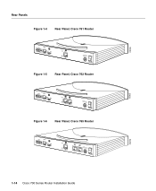
H5906 Rear Panels Figure 1-4 Rear Panel, Cisco 761 Router CONFIG 10BASET NODE HUB Link ISDN S/T S0 +-350VV------10.5.2AA++/-/-52%5% Figure 1-5 Rear Panel, Cisco 762 Router CONFIG 10BASET NODE HUB Link ISDN S/T ISDN U S0 NT-1 +-350VV------10.5.2AA++/-/-52%5% Figure 1-6 Rear Panel, Cisco 765 Router CONFIG 10BASET NODE HUB Link ISDN S/T S0 +-350VV------10.5.2AA++/-/-52%5% H5905 H5789 1-14 Cisco 700 Series Router Installation Guide
H5906 Rear Panels Figure 1-4 Rear Panel, Cisco 761 Router CONFIG 10BASET NODE HUB Link ISDN S/T S0 +-350VV------10.5.2AA++/-/-52%5% Figure 1-5 Rear Panel, Cisco 762 Router CONFIG 10BASET NODE HUB Link ISDN S/T ISDN U S0 NT-1 +-350VV------10.5.2AA++/-/-52%5% Figure 1-6 Rear Panel, Cisco 765 Router CONFIG 10BASET NODE HUB Link ISDN S/T S0 +-350VV------10.5.2AA++/-/-52%5% H5905 H5789 1-14 Cisco 700 Series Router Installation Guide
Installation Guide
Page 29
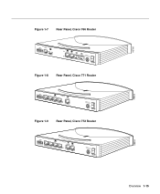
H5788 Figure 1-7 Rear Panel, Cisco 766 Router CONFIG 10BASET NODE HUB Link ISDN S/T ISDN U S 0 NT-1 +-350VV------10.5.2AA++/-/-52%5% Figure 1-8 Rear Panel, Cisco 771 Router CONFIG 4 3 10BA2 SET CISCO 771 1 ISDN S/T S0 +-350VV------10.5.2AA++/-/-52%5% Figure 1-9 Rear Panel, Cisco 772 Router CONFIG 4 3 10BA2 SET CISCO 772 1 ISDN S/T ISDN U S0 NT-1 +-350VV------10.5.2AA++/-/-52%5% H8503 H8504 Overview 1-15
H5788 Figure 1-7 Rear Panel, Cisco 766 Router CONFIG 10BASET NODE HUB Link ISDN S/T ISDN U S 0 NT-1 +-350VV------10.5.2AA++/-/-52%5% Figure 1-8 Rear Panel, Cisco 771 Router CONFIG 4 3 10BA2 SET CISCO 771 1 ISDN S/T S0 +-350VV------10.5.2AA++/-/-52%5% Figure 1-9 Rear Panel, Cisco 772 Router CONFIG 4 3 10BA2 SET CISCO 772 1 ISDN S/T ISDN U S0 NT-1 +-350VV------10.5.2AA++/-/-52%5% H8503 H8504 Overview 1-15
Installation Guide
Page 30
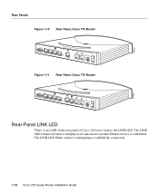
... series routers, the LINK LED. H8502 Rear Panels Figure 1-10 Rear Panel, Cisco 775 Router CONFIG 4 3 10BA2 SET CISCO 775 1 ISDN S/T S0 +-350VV------10.5.2AA++/-/-52%5% Figure 1-11 Rear Panel, Cisco 776 Router CONFIG 4 3 10BA2 SET CISCO 776 1 ISDN S/T ISDN U S0 NT-1 +-350VV------10.5.2AA++/-/-52%5% H7861 Rear-Panel LINK LED There is established. The LINK LED...
... series routers, the LINK LED. H8502 Rear Panels Figure 1-10 Rear Panel, Cisco 775 Router CONFIG 4 3 10BA2 SET CISCO 775 1 ISDN S/T S0 +-350VV------10.5.2AA++/-/-52%5% Figure 1-11 Rear Panel, Cisco 776 Router CONFIG 4 3 10BA2 SET CISCO 776 1 ISDN S/T ISDN U S0 NT-1 +-350VV------10.5.2AA++/-/-52%5% H7861 Rear-Panel LINK LED There is established. The LINK LED...

Installation Guide
Page 34
...Cisco 700 series router package is as follows: • One Cisco 700 series router. • One yellow Ethernet cable. • One red ISDN U cable (Cisco 772 and Cisco 776 routers only). • One orange ISDN S/T cable (Cisco 771 and Cisco... • One black power supply cord. • One Cisco 700 Series Router Installation Guide. • One Documentation CD-ROM set. (The Cisco 700 Series Command Reference is on Disk 2 of the CD...-ROM set.) • One Cisco 700 Quick Reference Guide. • One Cisco Fast Step CD-ROM....
...Cisco 700 series router package is as follows: • One Cisco 700 series router. • One yellow Ethernet cable. • One red ISDN U cable (Cisco 772 and Cisco 776 routers only). • One orange ISDN S/T cable (Cisco 771 and Cisco... • One black power supply cord. • One Cisco 700 Series Router Installation Guide. • One Documentation CD-ROM set. (The Cisco 700 Series Command Reference is on Disk 2 of the CD...-ROM set.) • One Cisco 700 Quick Reference Guide. • One Cisco Fast Step CD-ROM....
Installation Guide
Page 39
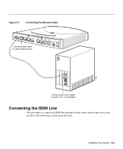
Installing Your Router 3-3 The following sections describe each. Figure 3-1 Connecting the Ethernet Cable CONFIG 4 3 10BA2 SET CISCO 776 1 ISDN S/T ISDN U Connect yellow cable to yellow Ethernet port S0 NT-1 +-350VV------10.5.2AA++/-/-52%5% ETH 17259 SER 0 OK LAN AUX Connect other end of cable to server, PC, or workstation Connecting the ISDN Line The procedure to connect an ISDN line depends on the router and in some cases your location.
Installing Your Router 3-3 The following sections describe each. Figure 3-1 Connecting the Ethernet Cable CONFIG 4 3 10BA2 SET CISCO 776 1 ISDN S/T ISDN U Connect yellow cable to yellow Ethernet port S0 NT-1 +-350VV------10.5.2AA++/-/-52%5% ETH 17259 SER 0 OK LAN AUX Connect other end of cable to server, PC, or workstation Connecting the ISDN Line The procedure to connect an ISDN line depends on the router and in some cases your location.
Installation Guide
Page 42
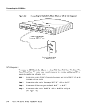
...the ISDN Line Figure 3-2 Connecting to the ISDN S/T Port When an NT1 Is Not Required CONFIG 4 3 10BA2 SET CISCO 776 1 ISDN S/T ISDN U S0 NT-1 +-350VV------10.5.2AA++/-/-52%5% Connect orange cable to orange ISDN S/T port 12760 Connect orange cable to ISDN wall jack NT1 Required To... connect an ISDN line to the S/T port of a Cisco 761, Cisco 762, Cisco 765, Cisco 771, Cisco 772, or Cisco 775 router when your telephone service ...
...the ISDN Line Figure 3-2 Connecting to the ISDN S/T Port When an NT1 Is Not Required CONFIG 4 3 10BA2 SET CISCO 776 1 ISDN S/T ISDN U S0 NT-1 +-350VV------10.5.2AA++/-/-52%5% Connect orange cable to orange ISDN S/T port 12760 Connect orange cable to ISDN wall jack NT1 Required To... connect an ISDN line to the S/T port of a Cisco 761, Cisco 762, Cisco 765, Cisco 771, Cisco 772, or Cisco 775 router when your telephone service ...
Installation Guide
Page 43
.... This will damage your router. Installing Your Router 3-7 Figure 3-3 Connecting to the ISDN S/T Port When an NT1 Is Required CONFIG 4 3 10BA2 SET CISCO 776 1 ISDN S/T ISDN U S0 NT-1 +-350VV------10.5.2AA++/-/-52%5% Connect orange cable to orange ISDN S/T port Connect orange cable to NT1 Connect ISDN U cable to NT1 Connect NT1 power...
.... This will damage your router. Installing Your Router 3-7 Figure 3-3 Connecting to the ISDN S/T Port When an NT1 Is Required CONFIG 4 3 10BA2 SET CISCO 776 1 ISDN S/T ISDN U S0 NT-1 +-350VV------10.5.2AA++/-/-52%5% Connect orange cable to orange ISDN S/T port Connect orange cable to NT1 Connect ISDN U cable to NT1 Connect NT1 power...
Installation Guide
Page 44
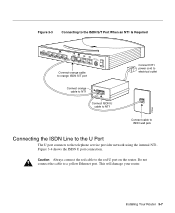
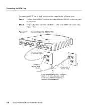
Step 1 Connect the red ISDN U cable to ISDN wall jack 3-8 Cisco 700 Series Router Installation Guide Step 2 Connect the other end of your wall jack has an RJ-11 connector, attach RJ-45-to-RJ-11 ... ISDN U cable to the ISDN wall socket. (See Figure 3-4.) Figure 3-4 Connecting to the ISDN U Port CONFIG 4 3 10BA2 SET CISCO 776 1 ISDN S/T ISDN U S0 NT-1 Connect red cable to red ISDN U port +-350VV------10.5.2AA++/-/-52%5% 17261 Connect red cable to ISDN wall jack RJ-45-to-RJ-11 adapter cable If your...
Step 1 Connect the red ISDN U cable to ISDN wall jack 3-8 Cisco 700 Series Router Installation Guide Step 2 Connect the other end of your wall jack has an RJ-11 connector, attach RJ-45-to-RJ-11 ... ISDN U cable to the ISDN wall socket. (See Figure 3-4.) Figure 3-4 Connecting to the ISDN U Port CONFIG 4 3 10BA2 SET CISCO 776 1 ISDN S/T ISDN U S0 NT-1 Connect red cable to red ISDN U port +-350VV------10.5.2AA++/-/-52%5% 17261 Connect red cable to ISDN wall jack RJ-45-to-RJ-11 adapter cable If your...
Installation Guide
Page 45
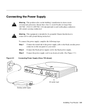
Warning This equipment is intended to an electrical outlet. (See Figure 3-5.) Connecting Power Supply (Cisco 765 shown) H5065 CONFIG 10BASET NODE HUB Link ISDN S/T S0 +-350VV------10.5.2AA++/-/-52%5% Desktop power supply DC power input Installing Your Router 3-9 Step 3 Connect the power supply cord to be grounded. To connect the power supply, ...
Warning This equipment is intended to an electrical outlet. (See Figure 3-5.) Connecting Power Supply (Cisco 765 shown) H5065 CONFIG 10BASET NODE HUB Link ISDN S/T S0 +-350VV------10.5.2AA++/-/-52%5% Desktop power supply DC power input Installing Your Router 3-9 Step 3 Connect the power supply cord to be grounded. To connect the power supply, ...

Installation Guide
Page 46
... the boot process, which takes a few minutes. The CH1 LED also turns on . All the LEDs are not correct, see Chapter 5, "Troubleshooting Cisco 700 Series Routers." On for 1 minute. 3-10 Cisco 700 Series Router Installation Guide If the LEDs do not behave as they relate to the LAN and the WAN. If your...
... the boot process, which takes a few minutes. The CH1 LED also turns on . All the LEDs are not correct, see Chapter 5, "Troubleshooting Cisco 700 Series Routers." On for 1 minute. 3-10 Cisco 700 Series Router Installation Guide If the LEDs do not behave as they relate to the LAN and the WAN. If your...
Installation Guide
Page 51
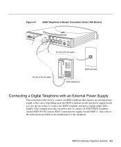
... an AT&T external power supply (model MSP-1). ISDN and Analog Telephone Devices 4-3 Figure 4-1 ISDN Telephone to Router Connection (Cisco 766 Shown) H10772 CONFIG 10BASET NODE HUB Link ISDN S/T ISDN U S0 NT-1 +-350VV------10.5.2AA++/-/-52%5% RJ-45-to-RJ-45 cable RJ-45-to-RJ-45 cable ISDN wall jack ISDN telephone...
... an AT&T external power supply (model MSP-1). ISDN and Analog Telephone Devices 4-3 Figure 4-1 ISDN Telephone to Router Connection (Cisco 766 Shown) H10772 CONFIG 10BASET NODE HUB Link ISDN S/T ISDN U S0 NT-1 +-350VV------10.5.2AA++/-/-52%5% RJ-45-to-RJ-45 cable RJ-45-to-RJ-45 cable ISDN wall jack ISDN telephone...
Installation Guide
Page 53
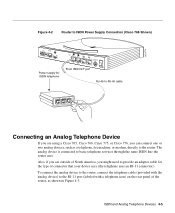
Also, if you are using a Cisco 765, Cisco 766, Cisco 775, or Cisco 776, you might need to provide an adapter cable for ISDN telephone Link ISDN S/T ISDN U S0 NT-1 +-350VV------10.5.2AA++/-/-52%5% From ISDN S/T port RJ-45-to-RJ-45 cable PHONE OTHER LINE Connecting an Analog Telephone Device If ...with the analog device) to basic telephone services through the same ISDN line the router uses. Figure 4-2 Router to ISDN Power Supply Connection (Cisco 766 Shown) H10774 CONFIG 10BASET NODE HUB Power supply for the type of connector that your device uses (the telephone uses an RJ-11...
Also, if you are using a Cisco 765, Cisco 766, Cisco 775, or Cisco 776, you might need to provide an adapter cable for ISDN telephone Link ISDN S/T ISDN U S0 NT-1 +-350VV------10.5.2AA++/-/-52%5% From ISDN S/T port RJ-45-to-RJ-45 cable PHONE OTHER LINE Connecting an Analog Telephone Device If ...with the analog device) to basic telephone services through the same ISDN line the router uses. Figure 4-2 Router to ISDN Power Supply Connection (Cisco 766 Shown) H10774 CONFIG 10BASET NODE HUB Power supply for the type of connector that your device uses (the telephone uses an RJ-11...

Installation Guide
Page 54
... Shown) H10773 CONFIG 10BASET NODE HUB Link ISDN S/T ISDN U S0 NT-1 +-350VV------10.5.2AA++/-/-52%5% Analog telephone RJ-11 telephone cable Supplementary Services This section describes how to configure the Cisco 765, Cisco 766, Cisco 775, and Cisco 776 routers for supported supplementary services. These are the only models that support the following supplementary services...
... Shown) H10773 CONFIG 10BASET NODE HUB Link ISDN S/T ISDN U S0 NT-1 +-350VV------10.5.2AA++/-/-52%5% Analog telephone RJ-11 telephone cable Supplementary Services This section describes how to configure the Cisco 765, Cisco 766, Cisco 775, and Cisco 776 routers for supported supplementary services. These are the only models that support the following supplementary services...
Installation Guide
Page 58
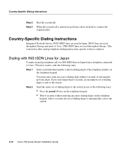
...analog telephone call over INS ISDN lines in Japan from a telephone connected to these countries. This section describes analog telephone dialing instructions specific to Cisco 700 series routers, take the following ways: • Press the pound (#) key on the telephone keypad. • Wait 6 seconds ... of dialing digits is automatically sent to the switch in Japan. Step 2 Send the entire set of dialing digits to the switch. 4-10 Cisco 700 Series Router Installation Guide After 6 seconds, the set of the telephone number on -hook to the switch. You must enter each individual...
...analog telephone call over INS ISDN lines in Japan from a telephone connected to these countries. This section describes analog telephone dialing instructions specific to Cisco 700 series routers, take the following ways: • Press the pound (#) key on the telephone keypad. • Wait 6 seconds ... of dialing digits is automatically sent to the switch in Japan. Step 2 Send the entire set of dialing digits to the switch. 4-10 Cisco 700 Series Router Installation Guide After 6 seconds, the set of the telephone number on -hook to the switch. You must enter each individual...
Installation Guide
Page 72
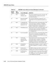
The call resume request contained a Call Identify information element that indicates that an attempt was asked to your ISDN service provider. 5-10 Cisco 700 Series Router Installation Guide The network received a call resume request. Indicates that the call identity is being used for a suspended call. An invalid message ...
The call resume request contained a Call Identify information element that indicates that an attempt was asked to your ISDN service provider. 5-10 Cisco 700 Series Router Installation Guide The network received a call resume request. Indicates that the call identity is being used for a suspended call. An invalid message ...

Installation Guide
Page 88
... the ASCII terminal or PC. The Connection Description window displays. Establishing a Terminal Connection Figure B-1 Console Cable Connection (Cisco 766 Shown) H5063 CONFIG 10BASET NODE HUB Console cable Link ISDN S/T ISDN U S0 NT-1 +-350VV------10.5.2AA++/-/-52%5% Step 2 Connect the other end of the Connection Description window. Set the port as follows: •...
... the ASCII terminal or PC. The Connection Description window displays. Establishing a Terminal Connection Figure B-1 Console Cable Connection (Cisco 766 Shown) H5063 CONFIG 10BASET NODE HUB Console cable Link ISDN S/T ISDN U S0 NT-1 +-350VV------10.5.2AA++/-/-52%5% Step 2 Connect the other end of the Connection Description window. Set the port as follows: •...
