

Hardware Installation Guide
Page 2
... a partnership relationship between Cisco and any interference to radio communications. Cisco Aironet 1100 Series Access Point Hardware Installation Guide © 2006 Cisco Systems, Inc. The following measures: • Turn the television or radio antenna until the interference stops. • Move the equipment to one of its affiliates in the United States and certain other company. (0609R) Any Internet Protocol (IP) addresses used in this product...
... a partnership relationship between Cisco and any interference to radio communications. Cisco Aironet 1100 Series Access Point Hardware Installation Guide © 2006 Cisco Systems, Inc. The following measures: • Turn the television or radio antenna until the interference stops. • Move the equipment to one of its affiliates in the United States and certain other company. (0609R) Any Internet Protocol (IP) addresses used in this product...
Hardware Installation Guide
Page 8
...," describes how to access the document that provides translations of conformity and regulatory information for basic problems with the autonomous access point. Chapter 6, "Troubleshooting Lightweight Access Points," provides troubleshooting procedures for the access point. Appendix C, "Access Point Specifications," lists technical specifications for basic problems with controller information. Appendix F, "Configuring DHCP Option 43 for Lightweight Access Points," describes the procedure to convey instructions and information: Command descriptions use these conventions: •...
...," describes how to access the document that provides translations of conformity and regulatory information for basic problems with the autonomous access point. Chapter 6, "Troubleshooting Lightweight Access Points," provides troubleshooting procedures for the access point. Appendix C, "Access Point Specifications," lists technical specifications for basic problems with controller information. Appendix F, "Configuring DHCP Option 43 for Lightweight Access Points," describes the procedure to convey instructions and information: Command descriptions use these conventions: •...

Hardware Installation Guide
Page 16
... a wide range of general networking, training, and certification titles. Join a discussion at this URL: http://www.cisco.com/discuss/networking • "What's New in Cisco Documentation" at this online publication is updated twice a year and includes the latest Cisco channel product offerings. You can access the Internet Protocol Journal at this URL: http://www.cisco.com/en/US/learning/index.html Cisco Aironet 1100 Series Access Point Hardware Installation Guide xvi...
... a wide range of general networking, training, and certification titles. Join a discussion at this URL: http://www.cisco.com/discuss/networking • "What's New in Cisco Documentation" at this online publication is updated twice a year and includes the latest Cisco channel product offerings. You can access the Internet Protocol Journal at this URL: http://www.cisco.com/en/US/learning/index.html Cisco Aironet 1100 Series Access Point Hardware Installation Guide xvi...
Hardware Installation Guide
Page 17
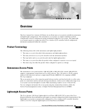
... maintained within the access points. Autonomous Access Points The autonomous access point (models: AIR-AP1120B or AIR-AP1121G) (model: AIR-AP1252) supports a management system based on Cisco IOS software. The lightweight access point is part of the Cisco Integrated Wireless Network Solution and requires no manual configuration before being mounted. Lightweight Access Points The Cisco Aironet 1100 Series Lightweight Access Point (AIR-LAP1121G) is automatically configured by a Cisco wireless LAN controller (hereafter called a controller) using the command-line interface (CLI), the...
... maintained within the access points. Autonomous Access Points The autonomous access point (models: AIR-AP1120B or AIR-AP1121G) (model: AIR-AP1252) supports a management system based on Cisco IOS software. The lightweight access point is part of the Cisco Integrated Wireless Network Solution and requires no manual configuration before being mounted. Lightweight Access Points The Cisco Aironet 1100 Series Lightweight Access Point (AIR-LAP1121G) is automatically configured by a Cisco wireless LAN controller (hereafter called a controller) using the command-line interface (CLI), the...

Hardware Installation Guide
Page 18
... a secure key distribution, using LWAPP discovery mechanisms and then sends it to autonomous mode). When the access point is joined, the access point downloads its software if the versions on the following topics: • Hardware Features, page 1-3 • Network Examples with Autonomous Access Points, page 1-5 • Network Example with Lightweight Access Points, page 1-9 Cisco Aironet 1100 Series Access Point Hardware Installation Guide 1-2 OL-4309-07 LWAPP is tunneled through the controller. In the Cisco Centralized Wireless LAN architecture, access points...
... a secure key distribution, using LWAPP discovery mechanisms and then sends it to autonomous mode). When the access point is joined, the access point downloads its software if the versions on the following topics: • Hardware Features, page 1-3 • Network Examples with Autonomous Access Points, page 1-5 • Network Example with Lightweight Access Points, page 1-9 Cisco Aironet 1100 Series Access Point Hardware Installation Guide 1-2 OL-4309-07 LWAPP is tunneled through the controller. In the Cisco Centralized Wireless LAN architecture, access points...

Hardware Installation Guide
Page 19
... dipole integrated antennas. Key hardware features of the 1100 series access point include: • Single Radio Operation, page 1-3 • Ethernet Port, page 1-3 • LEDs, page 1-4 • Power Sources, page 1-4 • UL 2043 Certification, page 1-5 • Anti-Theft Features, page 1-5 Figure 1-1 shows the location of some of the hardware features of the access point. Ethernet Port The auto-sensing Ethernet port accepts an RJ-45 connector, linking the access point to support new radio technologies...
... dipole integrated antennas. Key hardware features of the 1100 series access point include: • Single Radio Operation, page 1-3 • Ethernet Port, page 1-3 • LEDs, page 1-4 • Power Sources, page 1-4 • UL 2043 Certification, page 1-5 • Anti-Theft Features, page 1-5 Figure 1-1 shows the location of some of the hardware features of the access point. Ethernet Port The auto-sensing Ethernet port accepts an RJ-45 connector, linking the access point to support new radio technologies...
Hardware Installation Guide
Page 20
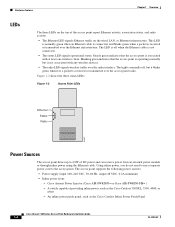
... one wireless client. The access point supports the following power sources: • Power supply (input 100-240 VAC, 50-60 Hz, output 48 VDC, 0.2A minimum) • Inline power from an external power module or through inline power using the Ethernet cable. The LED is off , but is not connected. • The status LED signals operational status. Blinking green indicates that the access point is associated with any wireless devices. • The radio LED signals wireless traffic over the Ethernet infrastructure. A switch capable...
... one wireless client. The access point supports the following power sources: • Power supply (input 100-240 VAC, 50-60 Hz, output 48 VDC, 0.2A minimum) • Inline power from an external power module or through inline power using the Ethernet cable. The LED is off , but is not connected. • The status LED signals operational status. Blinking green indicates that the access point is associated with any wireless devices. • The radio LED signals wireless traffic over the Ethernet infrastructure. A switch capable...
Hardware Installation Guide
Page 21
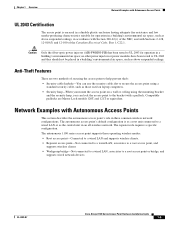
... power injector (AIR-PWRINJ-FIB) has been tested to a root access point or bridge, and supports wired network devices. Anti-Theft Features There are Master Lock models 120T and 121T or equivalent. Network Examples with a padlock. The autonomous 1100 series access point supports these operating wireless modes: • Root access point-Connected to a wired LAN and supports wireless clients. • Repeater access point-Not connected to a wired LAN, associates to a root access point, and supports wireless clients • Workgroup bridge-Not connected to a wired LAN...
... power injector (AIR-PWRINJ-FIB) has been tested to a root access point or bridge, and supports wired network devices. Anti-Theft Features There are Master Lock models 120T and 121T or equivalent. Network Examples with a padlock. The autonomous 1100 series access point supports these operating wireless modes: • Root access point-Connected to a wired LAN and supports wireless clients. • Repeater access point-Not connected to a wired LAN, associates to a root access point, and supports wireless clients • Workgroup bridge-Not connected to a wired LAN...

Hardware Installation Guide
Page 23
... Access Point Hardware Installation Guide 1-7 Consult the Cisco IOS Software Configuration Guide for Cisco Aironet Access Points for the client. Note Non-Cisco client devices might have difficulty communicating with Autonomous Access Points Repeater Unit that Extends Wireless Range An autonomous access point can be configured as a stand-alone repeater to extend the range of your infrastructure or to the wired LAN. Figure 1-4 Access Point as a repeater. The data is sent through the route that blocks radio communication. The repeater forwards traffic between wireless users...
... Access Point Hardware Installation Guide 1-7 Consult the Cisco IOS Software Configuration Guide for Cisco Aironet Access Points for the client. Note Non-Cisco client devices might have difficulty communicating with Autonomous Access Points Repeater Unit that Extends Wireless Range An autonomous access point can be configured as a stand-alone repeater to extend the range of your infrastructure or to the wired LAN. Figure 1-4 Access Point as a repeater. The data is sent through the route that blocks radio communication. The repeater forwards traffic between wireless users...

Hardware Installation Guide
Page 31
... Lightweight Access Points Prior to the access points. Deploying the Access Points on the access point location maps or floor plans to your network planner or manager. OL-4309-07 Cisco Aironet 1100 Series Access Point Hardware Installation Guide 2-5 to create maps for precise wireless system management. When you configure a DHCP server with untagged access ports for later deployment is called priming the access point. Cisco switches support a DHCP server option. The process of storing controller IP addresses in the access point non-volatile...
... Lightweight Access Points Prior to the access points. Deploying the Access Points on the access point location maps or floor plans to your network planner or manager. OL-4309-07 Cisco Aironet 1100 Series Access Point Hardware Installation Guide 2-5 to create maps for precise wireless system management. When you configure a DHCP server with untagged access ports for later deployment is called priming the access point. Cisco switches support a DHCP server option. The process of storing controller IP addresses in the access point non-volatile...

Hardware Installation Guide
Page 32
... Access Point LEDs" section on the Wireless Network Chapter 2 Installing the Access Point Step 4 b. For specific instructions, see the "Connecting the Ethernet and Power Cables" section on page 3-9). d. For additional information, refer to the Mounting on page 3-6). - Deploying the Access Points on page 6-3. A master controller should only be used for configuring access points and not in a working network. Cisco Aironet 1100 Series Access Point Hardware Installation Guide 2-6 OL-4309-07 Mount the access point at the indicated destination using a padlock or security cable...
... Access Point LEDs" section on the Wireless Network Chapter 2 Installing the Access Point Step 4 b. For specific instructions, see the "Connecting the Ethernet and Power Cables" section on page 3-9). d. For additional information, refer to the Mounting on page 3-6). - Deploying the Access Points on page 6-3. A master controller should only be used for configuring access points and not in a working network. Cisco Aironet 1100 Series Access Point Hardware Installation Guide 2-6 OL-4309-07 Mount the access point at the indicated destination using a padlock or security cable...
Hardware Installation Guide
Page 34
...-VDC power port labeled 48VDC on the access point. Using the power injector with other end labeled To Network to the 10/100 Ethernet LAN. Note If you use a power injector to power the access point, you are using a local power source: Step 1 Step 2 Step 3 Step 4 Connect the Ethernet cable to the RJ-45 Ethernet connector labeled Ethernet on the access point. Connect the other Ethernet-ready devices can damage the equipment. Connecting the Ethernet and Power Cables Chapter 2 Installing the Access Point Connecting...
...-VDC power port labeled 48VDC on the access point. Using the power injector with other end labeled To Network to the 10/100 Ethernet LAN. Note If you use a power injector to power the access point, you are using a local power source: Step 1 Step 2 Step 3 Step 4 Connect the Ethernet cable to the RJ-45 Ethernet connector labeled Ethernet on the access point. Connect the other Ethernet-ready devices can damage the equipment. Connecting the Ethernet and Power Cables Chapter 2 Installing the Access Point Connecting...

Hardware Installation Guide
Page 61
... Green - Blinking amber Amber Red Firmware - Red Upgrade Radio LED Green Red Blinking green - Green - - Starting Cisco IOS. Amber Red Amber Blinking amber - Boot environment error. Maximum retries or buffer full occurred on the radio. Ethernet initialization test. Transmitting/receiving radio packets. Blinking amber - check the unit's SSID and WEP settings. No Cisco IOS image file. Association status Amber Green - - Ethernet failure during image recovery. Reset Failure Red Status LED - try disconnecting and reconnecting unit power...
... Green - Blinking amber Amber Red Firmware - Red Upgrade Radio LED Green Red Blinking green - Green - - Starting Cisco IOS. Amber Red Amber Blinking amber - Boot environment error. Maximum retries or buffer full occurred on the radio. Ethernet initialization test. Transmitting/receiving radio packets. Blinking amber - check the unit's SSID and WEP settings. No Cisco IOS image file. Association status Amber Green - - Ethernet failure during image recovery. Reset Failure Red Status LED - try disconnecting and reconnecting unit power...

Hardware Installation Guide
Page 63
..., click Network Interfaces > Radio0-802.11B or Radio0-802.11G and the radio status page displays. The access point default SSID is Cisco. If a wireless client is no default SSID. An Enter Network Password window appears. For example, if you set WEP Key 3 on setting the access point's WEP keys. Security Settings Wireless clients attempting to authenticate with your access point, contact the system administrator for proper security settings in the client adapter and for instructions on your access point and any wireless devices with which it as EAP or LEAP, MAC address...
..., click Network Interfaces > Radio0-802.11B or Radio0-802.11G and the radio status page displays. The access point default SSID is Cisco. If a wireless client is no default SSID. An Enter Network Password window appears. For example, if you set WEP Key 3 on setting the access point's WEP keys. Security Settings Wireless clients attempting to authenticate with your access point, contact the system administrator for proper security settings in the client adapter and for instructions on your access point and any wireless devices with which it as EAP or LEAP, MAC address...

Hardware Installation Guide
Page 65
... that device displays. Click the MAC address of packets to 1400 bytes) in the browser address line. The default username is Cisco and the default password is Cisco. An Enter Network Password window appears. If you may need to use a continuous test, follow these steps: a. Chapter 5 Troubleshooting Autonomous Access Points Running the Ping or Link Test Running the Ping or Link Test You can use the ping or link test to factory defaults, including passwords, WEP keys, the IP address, and the SSID...
... that device displays. Click the MAC address of packets to 1400 bytes) in the browser address line. The default username is Cisco and the default password is Cisco. An Enter Network Password window appears. If you may need to use a continuous test, follow these steps: a. Chapter 5 Troubleshooting Autonomous Access Points Running the Ping or Link Test Running the Ping or Link Test You can use the ping or link test to factory defaults, including passwords, WEP keys, the IP address, and the SSID...

Hardware Installation Guide
Page 66
... the access point. An Enter Network Password window appears. The default username is Cisco and the default password is configured with the factory default values including the IP address (set to 3 seconds), and release the button. Resetting to the Default Configuration Chapter 5 Troubleshooting Autonomous Access Points Using the MODE Button Follow these steps to delete the current configuration and return all access point settings to the factory defaults using the MODE button: Step 1 Step 2 Step 3 Step 4 Disconnect power (the power jack for external power or the Ethernet cable for...
... the access point. An Enter Network Password window appears. The default username is Cisco and the default password is configured with the factory default values including the IP address (set to 3 seconds), and release the button. Resetting to the Default Configuration Chapter 5 Troubleshooting Autonomous Access Points Using the MODE Button Follow these steps to delete the current configuration and return all access point settings to the factory defaults using the MODE button: Step 1 Step 2 Step 3 Step 4 Disconnect power (the power jack for external power or the Ethernet cable for...

Hardware Installation Guide
Page 67
... Web browser interface or by the Status LED blinking green. Using the MODE button You can use the MODE button when the access point has a corrupt firmware image. For additional information, refer to 30 seconds), and release the MODE button. However, you can use must reload the image from an active Trivial File Transfer Protocol (TFTP) server on a PC connected to factory defaults, including passwords, WEP keys, the access point IP address, and SSIDs. Disconnect power (the power jack for external power or the Ethernet cable...
... Web browser interface or by the Status LED blinking green. Using the MODE button You can use the MODE button when the access point has a corrupt firmware image. For additional information, refer to 30 seconds), and release the MODE button. However, you can use must reload the image from an active Trivial File Transfer Protocol (TFTP) server on a PC connected to factory defaults, including passwords, WEP keys, the access point IP address, and SSIDs. Disconnect power (the power jack for external power or the Ethernet cable...

Hardware Installation Guide
Page 74
...1100 Series Access Point Hardware Installation Guide 6-4 OL-4309-07 Checking the Lightweight Access Point LEDs Chapter 6 Troubleshooting Lightweight Access Points Table 6-1 Top Panel LED Signals Message type Ethernet LED Status LED Radio LED Meaning Boot loader status Green - - Blinking green Blinking green Flash memory test. status Green - At least one wireless client device is operational. Green Green - Blinking green - Transmitting/receiving radio packets. Ethernet link is associated with the controller information. 1. Red Errors - Red Red DRAM...
...1100 Series Access Point Hardware Installation Guide 6-4 OL-4309-07 Checking the Lightweight Access Point LEDs Chapter 6 Troubleshooting Lightweight Access Points Table 6-1 Top Panel LED Signals Message type Ethernet LED Status LED Radio LED Meaning Boot loader status Green - - Blinking green Blinking green Flash memory test. status Green - At least one wireless client device is operational. Green Green - Blinking green - Transmitting/receiving radio packets. Ethernet link is associated with the controller information. 1. Red Errors - Red Red DRAM...

Hardware Installation Guide
Page 76
... access point documentation, click Cisco Aironet 1100 Series listed under "Wireless LAN Access." Click IOS. Click WIRELESS LAN for an access point image file, such as 12.3.11.JA. Step 1 Step 2 Step 3 Step 4 Step 5 Step 6 Step 7 Step 8 Step 9 Use your Cisco.com username and password and click OK. On the Enter Network Password window, enter your Internet browser to view and configure the MODE button: 1) config ap rst-button enable /all 2) config ap rst-button disable /all LEDs turning green followed by all 3) show ap config...
... access point documentation, click Cisco Aironet 1100 Series listed under "Wireless LAN Access." Click IOS. Click WIRELESS LAN for an access point image file, such as 12.3.11.JA. Step 1 Step 2 Step 3 Step 4 Step 5 Step 6 Step 7 Step 8 Step 9 Use your Cisco.com username and password and click OK. On the Enter Network Password window, enter your Internet browser to view and configure the MODE button: 1) config ap rst-button enable /all 2) config ap rst-button disable /all LEDs turning green followed by all 3) show ap config...

Hardware Installation Guide
Page 102
... capable switch. c. All the access point LEDs blink simultaneously during the download. Use the CLI, web-browser interface, or Cisco WCS procedures as described in LWAPP Layer 3 mode and ensure its IP address and controller information using DHCP, DNS, OTAP, or IP subnet broadcast. In multi-controller environments, You can set one location, you can use a Cisco WCS server to control, configure, and redistribute all LEDs off), check to ensure that you can optionally use the show network config...
... capable switch. c. All the access point LEDs blink simultaneously during the download. Use the CLI, web-browser interface, or Cisco WCS procedures as described in LWAPP Layer 3 mode and ensure its IP address and controller information using DHCP, DNS, OTAP, or IP subnet broadcast. In multi-controller environments, You can set one location, you can use a Cisco WCS server to control, configure, and redistribute all LEDs off), check to ensure that you can optionally use the show network config...


