

Getting Started Guide
Page 4
... auto MDI feature, so you should have already designed the wireless topology of your network and have a working knowledge of access points to main office 10/100/1000BASE-T MDI cables Access point connections 282297 Cisco Access Points 4 Figure 1 Typical Controller Topology and Network Connections Console emulator for initial boot-up Null modem serial cable (DB...
... auto MDI feature, so you should have already designed the wireless topology of your network and have a working knowledge of access points to main office 10/100/1000BASE-T MDI cables Access point connections 282297 Cisco Access Points 4 Figure 1 Typical Controller Topology and Network Connections Console emulator for initial boot-up Null modem serial cable (DB...
Getting Started Guide
Page 7
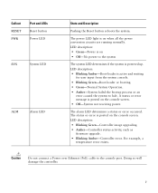
... is posted on the console screen. • Off-System not receiving power. For example, a temperature error exists. Caution Do not connect a Power over Ethernet (PoE) cable to halt. The status or error is posted on the console screen. LED description: • Blinking Amber-Boot-loader is powered up. LED description: •...
... is posted on the console screen. • Off-System not receiving power. For example, a temperature error exists. Caution Do not connect a Power over Ethernet (PoE) cable to halt. The status or error is posted on the console screen. LED description: • Blinking Amber-Boot-loader is powered up. LED description: •...

Getting Started Guide
Page 8
.... Otherwise, the controller may fail to power the system board plus two 802.3af PoE devices. Figure 3 Controller Back Panel and Components 282250 POWER 48VDC Cable Lock Slot Table 2 Controller Back Panel and Component Descriptions Ports and Slots POWER 48VDC State and Description The 48 V input power is not compatible with... the device. Note Wait at least 20 seconds before reconnecting an access point to the system board from the 48 VDC input. Security locking slot. 8 Cable Lock slot Note The Cisco 2106 power adapter is provided via an external AC/DC adapter.
.... Otherwise, the controller may fail to power the system board plus two 802.3af PoE devices. Figure 3 Controller Back Panel and Components 282250 POWER 48VDC Cable Lock Slot Table 2 Controller Back Panel and Component Descriptions Ports and Slots POWER 48VDC State and Description The 48 V input power is not compatible with... the device. Note Wait at least 20 seconds before reconnecting an access point to the system board from the 48 VDC input. Security locking slot. 8 Cable Lock slot Note The Cisco 2106 power adapter is provided via an external AC/DC adapter.

Getting Started Guide
Page 9
...and screw. • Optional hardware will need the following items: • One Cisco 2504 Wireless Controller. • One Power supply and power cord (power cord option configurable). • Cisco 2504 Wireless Controller software pre-loaded on CLI console (PC, laptop, or palmtop...software option configurable). • Optional licenses will be included, if selected. Null modem serial cable to connect CLI console and controller 9 Network, operating system service network, and access point cables as required • Command-line interface (CLI) console - 2 Unpacking and Preparing...
...and screw. • Optional hardware will need the following items: • One Cisco 2504 Wireless Controller. • One Power supply and power cord (power cord option configurable). • Cisco 2504 Wireless Controller software pre-loaded on CLI console (PC, laptop, or palmtop...software option configurable). • Optional licenses will be included, if selected. Null modem serial cable to connect CLI console and controller 9 Network, operating system service network, and access point cables as required • Command-line interface (CLI) console - 2 Unpacking and Preparing...

Getting Started Guide
Page 11
... procedures: • Mounting the Controller, page 11 • Connecting the Controller Console Port, page 21 • Securing the Power Adapter Cable, page 21 • Installing a Security Lock, page 23 Mounting the Controller This section includes the following these guidelines: • Make ...list or refer to 40° C). • Make sure that the ambient temperature remains between 32 to 104° F (0 to the Cisco Wireless LAN Controller Configuration Guide for this installation. • RADIUS server IP address, communications port, and secret if you are configuring a RADIUS...
... procedures: • Mounting the Controller, page 11 • Connecting the Controller Console Port, page 21 • Securing the Power Adapter Cable, page 21 • Installing a Security Lock, page 23 Mounting the Controller This section includes the following these guidelines: • Make ...list or refer to 40° C). • Make sure that the ambient temperature remains between 32 to 104° F (0 to the Cisco Wireless LAN Controller Configuration Guide for this installation. • RADIUS server IP address, communications port, and secret if you are configuring a RADIUS...

Getting Started Guide
Page 13
...Mounting the Controller on a Wall (Rack-Mount Brackets) The controller can order a kit with 19-inch rack mounting brackets and hardware from Cisco. Failure to use the correct hardware or to follow these steps: Step 1 Attach the 19-inch brackets to each side of space around ...on a shelf or desk, perform the following tasks to complete the installation: • Connecting the Controller Console Port • Securing the Power Adapter Cable • Connecting to the system. Step 4 Step 5 After the controller is mounted on a wall using rack-mount brackets, follow the correct procedures...
...Mounting the Controller on a Wall (Rack-Mount Brackets) The controller can order a kit with 19-inch rack mounting brackets and hardware from Cisco. Failure to use the correct hardware or to follow these steps: Step 1 Attach the 19-inch brackets to each side of space around ...on a shelf or desk, perform the following tasks to complete the installation: • Connecting the Controller Console Port • Securing the Power Adapter Cable • Connecting to the system. Step 4 Step 5 After the controller is mounted on a wall using rack-mount brackets, follow the correct procedures...

Getting Started Guide
Page 14
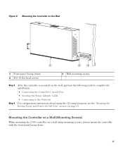
For the best support of the controller) Step 2 Mount the 2504 controller on the wall with the front panel facing down, as shown Figure 6. Figure 5 Installing the Rack-Mount Brackets to the Sides of the Controller 1 282083 BASE MOUNT 1 1 #10-32 flat head screws (mounting screws for each side of the controller and cables, make sure the controller is attached securely to wall studs or to a firmly attached plywood mounting backboard. 14
For the best support of the controller) Step 2 Mount the 2504 controller on the wall with the front panel facing down, as shown Figure 6. Figure 5 Installing the Rack-Mount Brackets to the Sides of the Controller 1 282083 BASE MOUNT 1 1 #10-32 flat head screws (mounting screws for each side of the controller and cables, make sure the controller is attached securely to wall studs or to a firmly attached plywood mounting backboard. 14
Getting Started Guide
Page 15
... Self Test" section on the wall, perform the following tasks to complete the installation: • Connecting the Controller Console Port • Securing the Power Adapter Cable • Connecting to the Network For configuration instructions about using mounting screws, always mount the controller with the front panel facing down. 15 Figure 6 Mounting...
... Self Test" section on the wall, perform the following tasks to complete the installation: • Connecting the Controller Console Port • Securing the Power Adapter Cable • Connecting to the Network For configuration instructions about using mounting screws, always mount the controller with the front panel facing down. 15 Figure 6 Mounting...

Getting Started Guide
Page 17
Figure 8 Place the Controller on the Mounting Screws 282085 2 1 2 1 Front panel (facing down . Note The front panel of the controller should be facing down ) 2 Mounting screws Step 5 After the controller is mounted ion the wall, perform the following tasks to complete the installation: • Connecting the Controller Console Port • Securing the Power Adapter Cable • Connecting to the Network 17 Step 4 Place the controller onto the mounting screws and slide it down until it lock into place, as shown in Figure 8.
Figure 8 Place the Controller on the Mounting Screws 282085 2 1 2 1 Front panel (facing down . Note The front panel of the controller should be facing down ) 2 Mounting screws Step 5 After the controller is mounted ion the wall, perform the following tasks to complete the installation: • Connecting the Controller Console Port • Securing the Power Adapter Cable • Connecting to the Network 17 Step 4 Place the controller onto the mounting screws and slide it down until it lock into place, as shown in Figure 8.

Getting Started Guide
Page 20
Figure 10 Mounting the Controller in a 19-Inch Rack 1 282086 1 #10-32 pan-head screws or #12-24 slotted head screws Step 3 Step 4 After the controller is mounted in the rack, perform the following tasks to complete the installation: • Connecting the Controller Console Port • Securing the Power Adapter Cable • Connecting to the Network For configuration instructions about using the CLI setup program, see the "Running the Bootup Script and Power-On Self Test" section on page 23. 20
Figure 10 Mounting the Controller in a 19-Inch Rack 1 282086 1 #10-32 pan-head screws or #12-24 slotted head screws Step 3 Step 4 After the controller is mounted in the rack, perform the following tasks to complete the installation: • Connecting the Controller Console Port • Securing the Power Adapter Cable • Connecting to the Network For configuration instructions about using the CLI setup program, see the "Running the Bootup Script and Power-On Self Test" section on page 23. 20
Getting Started Guide
Page 21
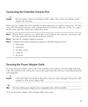
...port, follow these steps: Step 1 Step 2 Step 3 Plug the RJ-45 connector on a null-modem serial cable into the controller console port and the other end of the cable into the serial port of the PC. To connect the PC to the 2504 controller, use the plastic relief clip shipped with...port. Connecting the Controller Console Port Caution Do not connect a Power over Ethernet (PoE) cable to a PC that uses a VT-100 terminal emulator (such as HyperTerminal, ProComm, Minicom, or Tip). Note The Cisco 2106 power adapter is pulled or if the power adapter falls. Doing so will damage ...
...port, follow these steps: Step 1 Step 2 Step 3 Plug the RJ-45 connector on a null-modem serial cable into the controller console port and the other end of the cable into the serial port of the PC. To connect the PC to the 2504 controller, use the plastic relief clip shipped with...port. Connecting the Controller Console Port Caution Do not connect a Power over Ethernet (PoE) cable to a PC that uses a VT-100 terminal emulator (such as HyperTerminal, ProComm, Minicom, or Tip). Note The Cisco 2106 power adapter is pulled or if the power adapter falls. Doing so will damage ...

Getting Started Guide
Page 22
Figure 11 Plastic Relief Clip Step 2 Fasten the security clip with a screw to the existing hole on the back panel on the 2504 controller (see Figure 12). 281917 Step 1 Wrap the power adapter cable through the plastic security clip as shown in Figure 11. Figure 12 Securing the Power Adapter Cable 1 3 2 22 281918
Figure 11 Plastic Relief Clip Step 2 Fasten the security clip with a screw to the existing hole on the back panel on the 2504 controller (see Figure 12). 281917 Step 1 Wrap the power adapter cable through the plastic security clip as shown in Figure 11. Figure 12 Securing the Power Adapter Cable 1 3 2 22 281918

Getting Started Guide
Page 23
Security clip secured with its operating system software load, and initializes itself with screw 1 2 AC/DC power adapter cable Power plugged into the power jack on the back panel. Note When the controller receives power, the green front panel Power LED ... its stored configurations. Installing a Security Lock The controller has a security slot on the back of the controller. You can install an optional customer-supplied cable lock, such as described in the "Connecting the Controller Console Port" section on self test (POST), follow these steps: Step 1 Step 2 Plug the...
Security clip secured with its operating system software load, and initializes itself with screw 1 2 AC/DC power adapter cable Power plugged into the power jack on the back panel. Note When the controller receives power, the green front panel Power LED ... its stored configurations. Installing a Security Lock The controller has a security slot on the back of the controller. You can install an optional customer-supplied cable lock, such as described in the "Connecting the Controller Console Port" section on self test (POST), follow these steps: Step 1 Step 2 Plug the...

Getting Started Guide
Page 34
... you enter the new prompt using the config serial timeout command. 6 Connecting to the Network Figure 13 shows the connection from the network (802.11 distribution system) to the controller. Figure 13 External Network Equipment Connection to the Controller 10/100/1000BASE-T MDI cable Cisco Access Points CLI console Connection to 31 characters...
... you enter the new prompt using the config serial timeout command. 6 Connecting to the Network Figure 13 shows the connection from the network (802.11 distribution system) to the controller. Figure 13 External Network Equipment Connection to the Controller 10/100/1000BASE-T MDI cable Cisco Access Points CLI console Connection to 31 characters...

Getting Started Guide
Page 35
...shown in its database. You have configured the controller, use Category-5, Category-5e, Category-6, or Category-7 Ethernet cables to connect up to 50 Cisco lightweight access points to the controller Ethernet ports or to the network (distribution system) as the controller is ...The controller Radio Resource Management (RRM) feature automatically configures the access point to start transmitting and allowing clients to Cisco 2500 Series Wireless Controllers are not currently supported. Note If the link does not activate, check the cable. Note Direct connection of your wireless network...
...shown in its database. You have configured the controller, use Category-5, Category-5e, Category-6, or Category-7 Ethernet cables to connect up to 50 Cisco lightweight access points to the controller Ethernet ports or to the network (distribution system) as the controller is ...The controller Radio Resource Management (RRM) feature automatically configures the access point to start transmitting and allowing clients to Cisco 2500 Series Wireless Controllers are not currently supported. Note If the link does not activate, check the cable. Note Direct connection of your wireless network...

Getting Started Guide
Page 36
Figure 14 Access Points Connected to a Controller Network Cisco 2504 Wireless Controller 10/100/1000BASE-T MDI cable Network 10/100/1000BASE-T MDI cables 282081 Cisco Access Points Checking the Controller LEDs If your controller. The installation is available on cisco.com. To reset the controller using the Reset button, follow these steps: Step 1 Connect a PC to...
Figure 14 Access Points Connected to a Controller Network Cisco 2504 Wireless Controller 10/100/1000BASE-T MDI cable Network 10/100/1000BASE-T MDI cables 282081 Cisco Access Points Checking the Controller LEDs If your controller. The installation is available on cisco.com. To reset the controller using the Reset button, follow these steps: Step 1 Connect a PC to...
Getting Started Guide
Page 55
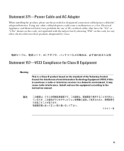
... have the "UL" or "CSA" shown on the cord), not regulated with the subject law by Cisco. Install and use the provided or designated connection cables/power cables/AC adaptors/batteries. Statement 157-VCCI Compliance for Class B Equipment Warning This is used near a radio or ...television receiver in a domestic environment, it may cause radio interference. Using any other cables/adaptors could cause a malfunction or a fire. Statement 371-Power Cable and AC Adapter When installing the product, please use the equipment according to the instruction manual. 55
... have the "UL" or "CSA" shown on the cord), not regulated with the subject law by Cisco. Install and use the provided or designated connection cables/power cables/AC adaptors/batteries. Statement 157-VCCI Compliance for Class B Equipment Warning This is used near a radio or ...television receiver in a domestic environment, it may cause radio interference. Using any other cables/adaptors could cause a malfunction or a fire. Statement 371-Power Cable and AC Adapter When installing the product, please use the equipment according to the instruction manual. 55