
Hardware Installation Guide
Page 2
... THIS REFERENCE. The following information is for FCC compliance of Class A devices: This equipment has been tested and found to this product not authorized by using one side or the other of Class B devices: The equipment described in part 15 of California. These limits are designed to radio communications. NOTWITHSTANDING ANY OTHER WARRANTY HEREIN, ALL DOCUMENT FILES AND SOFTWARE...
... THIS REFERENCE. The following information is for FCC compliance of Class A devices: This equipment has been tested and found to this product not authorized by using one side or the other of Class B devices: The equipment described in part 15 of California. These limits are designed to radio communications. NOTWITHSTANDING ANY OTHER WARRANTY HEREIN, ALL DOCUMENT FILES AND SOFTWARE...
Hardware Installation Guide
Page 6
... PC 2-17 Connecting the Power Supply 2-18 Mounting Your Router 2-18 Mounting on a Table 2-18 Mounting on a Wall 2-19 Verifying Installation 2-20 Where to Go from Here 2-22 Troubleshooting 3-1 Problems During First Startup 3-2 Problems After First Startup 3-3 Problems After Router Is Running 3-5 When Contacting Your Cisco Reseller 3-7 ISDN and IDSL Concepts A-1 Specifications and Cables B-1 System Specifications B-1 Port Connector Pinouts B-2 Cabling Specifications B-6 Ethernet Cable Specifications B-7 Maximum Cable Distances B-7 Cisco 800 Series Routers Hardware Installation Guide vi 78-5373...
... PC 2-17 Connecting the Power Supply 2-18 Mounting Your Router 2-18 Mounting on a Table 2-18 Mounting on a Wall 2-19 Verifying Installation 2-20 Where to Go from Here 2-22 Troubleshooting 3-1 Problems During First Startup 3-2 Problems After First Startup 3-3 Problems After Router Is Running 3-5 When Contacting Your Cisco Reseller 3-7 ISDN and IDSL Concepts A-1 Specifications and Cables B-1 System Specifications B-1 Port Connector Pinouts B-2 Cabling Specifications B-6 Ethernet Cable Specifications B-7 Maximum Cable Distances B-7 Cisco 800 Series Routers Hardware Installation Guide vi 78-5373...

Hardware Installation Guide
Page 7
... Cisco 800 Series Routers Hardware Installation Guide vii The goal of experience in installing routers. Note Means reader take note. Organization This guide contains the following information: • About This Guide-Describes audience, organization, conventions used in this guide. About This Guide This preface discusses the audience, organization, and conventions used in this guide, and how to access related documentation. • Overview-Contains router features and a description of router LEDs, ports...
... Cisco 800 Series Routers Hardware Installation Guide vii The goal of experience in installing routers. Note Means reader take note. Organization This guide contains the following information: • About This Guide-Describes audience, organization, conventions used in this guide. About This Guide This preface discusses the audience, organization, and conventions used in this guide, and how to access related documentation. • Overview-Contains router features and a description of router LEDs, ports...

Hardware Installation Guide
Page 11
... you to use Pretty Good Privacy (PGP) or a compatible product to encrypt any sensitive information that has the most recent creation date in your product serial number before placing a service call. 78-5373-04 Cisco 800 Series Routers Hardware Installation Guide xi Cisco Technical Support Website The Cisco Technical Support Website provides online documents and tools for certain products, by clicking the Tools & Resources link under...
... you to use Pretty Good Privacy (PGP) or a compatible product to encrypt any sensitive information that has the most recent creation date in your product serial number before placing a service call. 78-5373-04 Cisco 800 Series Routers Hardware Installation Guide xi Cisco Technical Support Website The Cisco Technical Support Website provides online documents and tools for certain products, by clicking the Tools & Resources link under...
Hardware Installation Guide
Page 16
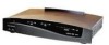
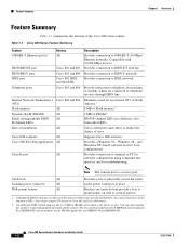
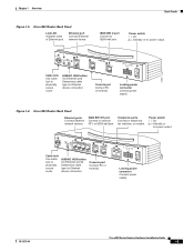
... Flash memory upgrade kit is a service port. Although the ISDN U interfaces on wall or vertical surface. 1. Provides connection to IDSL network. Cisco 800 Series Routers Hardware Installation Guide 1-2 78-5373-04 Provide connection to telephone, fax machine, or modem, which are MEM800-4D and MEM800-8D. You cannot connect S/T devices to reduce the chance of error. Wall-mount feature All Brackets on router bottom provide a way to terminal or PC for software configuration using command-line interface and...
... Flash memory upgrade kit is a service port. Although the ISDN U interfaces on wall or vertical surface. 1. Provides connection to IDSL network. Cisco 800 Series Routers Hardware Installation Guide 1-2 78-5373-04 Provide connection to telephone, fax machine, or modem, which are MEM800-4D and MEM800-8D. You cannot connect S/T devices to reduce the chance of error. Wall-mount feature All Brackets on router bottom provide a way to terminal or PC for software configuration using command-line interface and...
Hardware Installation Guide
Page 18
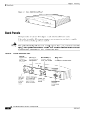
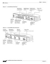
... cable Connect PC or type for Ethernet terminal. Ethernet port Connect Ethernet network device. Connecting the port to a public network that follows the European Union standards. ISDN BRI S/T port Connect to physically secure router. device connection. Power switch l = On. = Standby or no power output. 11666 LINK HUB NO HUB ETHERNET 10 BASE T Cisco 801 CONSOLE ISDN S/T Cable lock Use cable lock to external NT1 or ISDN wall jack. Figure 1-4 Cisco 801 Router Back Panel Link LED Indicates state of Ethernet port. Cisco 800 Series Routers Hardware Installation Guide...
... cable Connect PC or type for Ethernet terminal. Ethernet port Connect Ethernet network device. Connecting the port to a public network that follows the European Union standards. ISDN BRI S/T port Connect to physically secure router. device connection. Power switch l = On. = Standby or no power output. 11666 LINK HUB NO HUB ETHERNET 10 BASE T Cisco 801 CONSOLE ISDN S/T Cable lock Use cable lock to external NT1 or ISDN wall jack. Figure 1-4 Cisco 801 Router Back Panel Link LED Indicates state of Ethernet port. Cisco 800 Series Routers Hardware Installation Guide...
Hardware Installation Guide
Page 19
... T CONSOLE Cisco 802 ISDN U Cable lock Use cable lock to physically secure router. Console port Connect PC or terminal. PHONE 1 2 Locking power connector Connect power supply. 78-5373-04 Cisco 800 Series Routers Hardware Installation Guide 1-5 HUB NO HUB ETHERNET 10 BASE T 0 1 2 3 Cisco 803 CONSOLE ISDN S/T HUB/NO HUB button (for Ethernet port 0) Determines cable type for Ethernet device connection. Power switch l = On. = Standby or no power output. Console port Connect PC or terminal. Chapter 1 Overview Back Panels Figure 1-5 Cisco 802 Router Back Panel Link LED...
... T CONSOLE Cisco 802 ISDN U Cable lock Use cable lock to physically secure router. Console port Connect PC or terminal. PHONE 1 2 Locking power connector Connect power supply. 78-5373-04 Cisco 800 Series Routers Hardware Installation Guide 1-5 HUB NO HUB ETHERNET 10 BASE T 0 1 2 3 Cisco 803 CONSOLE ISDN S/T HUB/NO HUB button (for Ethernet port 0) Determines cable type for Ethernet device connection. Power switch l = On. = Standby or no power output. Console port Connect PC or terminal. Chapter 1 Overview Back Panels Figure 1-5 Cisco 802 Router Back Panel Link LED...
Hardware Installation Guide
Page 20
... IDSL Router Back Panel Link LED Indicates state of Ethernet port. Ethernet port Connect Ethernet network device. LINK TO TO HUB PC ETHERNET 10 BASE T CONSOLE Cisco 802 IDSL IDSL Cable lock Use cable lock to telephone, fax machine, or modem. HUB NO HUB ETHERNET 10 BASE T 0 1 2 3 HUB/NO HUB button (for Ethernet port 0) Determines cable type for Ethernet device connection. Locking power connector Connect power supply. 30771 Cisco 800 Series Routers Hardware Installation Guide 1-6 78-5373-04 Telephone ports Connect to physically secure router. PHONE 1 2 Locking power...
... IDSL Router Back Panel Link LED Indicates state of Ethernet port. Ethernet port Connect Ethernet network device. LINK TO TO HUB PC ETHERNET 10 BASE T CONSOLE Cisco 802 IDSL IDSL Cable lock Use cable lock to telephone, fax machine, or modem. HUB NO HUB ETHERNET 10 BASE T 0 1 2 3 HUB/NO HUB button (for Ethernet port 0) Determines cable type for Ethernet device connection. Locking power connector Connect power supply. 30771 Cisco 800 Series Routers Hardware Installation Guide 1-6 78-5373-04 Telephone ports Connect to physically secure router. PHONE 1 2 Locking power...
Hardware Installation Guide
Page 21
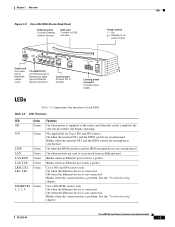
... the "Troubleshooting" chapter. Power switch l = On. = Standby or no power output. 30772 Cable lock Use cable lock to IDSL wall jack. Locking power connector Connect power supply. On when packets are attempting to or received from an Ethernet port. See the "Troubleshooting" chapter. 78-5373-04 Cisco 800 Series Routers Hardware Installation Guide 1-7 Table 1-3 LED Functions LED Color OK Green NT1 Green LINE LAN LAN RXD LAN TXD LKØ, LK1, LK2, LK3 Green Green Green Green Green ETHERNET Green 1, 2, 3, 4 Function On when power is not connected. Blinks when...
... the "Troubleshooting" chapter. Power switch l = On. = Standby or no power output. 30772 Cable lock Use cable lock to IDSL wall jack. Locking power connector Connect power supply. On when packets are attempting to or received from an Ethernet port. See the "Troubleshooting" chapter. 78-5373-04 Cisco 800 Series Routers Hardware Installation Guide 1-7 Table 1-3 LED Functions LED Color OK Green NT1 Green LINE LAN LAN RXD LAN TXD LKØ, LK1, LK2, LK3 Green Green Green Green Green ETHERNET Green 1, 2, 3, 4 Function On when power is not connected. Blinks when...

Hardware Installation Guide
Page 22
... this table. On when a call is connected on the second ISDN B channel. On when basic telephone service is connected. Note On Cisco 802 IDSL and Cisco 804 IDSL routers, either CH1 or CH2 is on if the router has an active data connection and the line speed is 64 kbps. Blinks when packets are received from the first ISDN B channel. Refer to the "Troubleshooting" chapter. On when Ethernet device is in use...
... this table. On when a call is connected on the second ISDN B channel. On when basic telephone service is connected. Note On Cisco 802 IDSL and Cisco 804 IDSL routers, either CH1 or CH2 is on if the router has an active data connection and the line speed is 64 kbps. Blinks when packets are received from the first ISDN B channel. Refer to the "Troubleshooting" chapter. On when Ethernet device is in use...

Hardware Installation Guide
Page 24
... the installation instructions before you must be handled according to user contact. Warning The ISDN connection is connected to telephone-network voltage (TNV) circuits. Warning If the symbol of public network can cause serious burns or weld the metal object to standby and unplug the power cord. Warning Before working on a system that follows the European Union standards. Cisco 800 Series Routers Hardware Installation Guide 2-2 78...
... the installation instructions before you must be handled according to user contact. Warning The ISDN connection is connected to telephone-network voltage (TNV) circuits. Warning If the symbol of public network can cause serious burns or weld the metal object to standby and unplug the power cord. Warning Before working on a system that follows the European Union standards. Cisco 800 Series Routers Hardware Installation Guide 2-2 78...
Hardware Installation Guide
Page 26
...; Connect the color-coded cables supplied by Cisco Systems to a public network that is missing or damaged, contact your router. If any of public network can connect the port directly to the color-coded ports on the back panel. • If you can cause severe injury or damage your router came in. Connecting the port to the Cisco 800 Series Routers Software Configuration Guide. Preventing Router Damage Chapter 2 Installation Preventing Router Damage Use the following : Cisco 800 Series Routers Hardware Installation Guide...
...; Connect the color-coded cables supplied by Cisco Systems to a public network that is missing or damaged, contact your router. If any of public network can connect the port directly to the color-coded ports on the back panel. • If you can cause severe injury or damage your router came in. Connecting the port to the Cisco 800 Series Routers Software Configuration Guide. Preventing Router Damage Chapter 2 Installation Preventing Router Damage Use the following : Cisco 800 Series Routers Hardware Installation Guide...
Hardware Installation Guide
Page 27
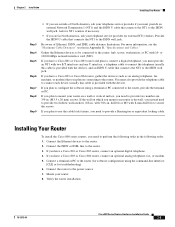
... ISDN wall jack. If you have a Cisco 803 or Cisco 804 router, connect an optional analog telephone, fax, or modem. 5. Installing Your Router To install the Cisco 800 series routers, you plan to provide two hollow wall-anchors (1/8-in. Verify the router installation. 78-5373-04 Cisco 800 Series Routers Hardware Installation Guide 2-5 For more information, see the "Maximum Cable Distances" section in Appendix B, "Specifications and Cables." If you need to configure the software using the command-line interface [CLI...
... ISDN wall jack. If you have a Cisco 803 or Cisco 804 router, connect an optional analog telephone, fax, or modem. 5. Installing Your Router To install the Cisco 800 series routers, you plan to provide two hollow wall-anchors (1/8-in. Verify the router installation. 78-5373-04 Cisco 800 Series Routers Hardware Installation Guide 2-5 For more information, see the "Maximum Cable Distances" section in Appendix B, "Specifications and Cables." If you need to configure the software using the command-line interface [CLI...

Hardware Installation Guide
Page 28
...) MDI-X (OUT) Cisco 800 Series Routers Hardware Installation Guide 2-6 78-5373-04 Table 2-2 Connecting Ethernet Devices Network Device Connected to Router Router Port Hub with equivalent to router HUB/NO HUB button Cisco 801 and 802 routers: Ethernet port Cisco 803 and 804 routers: Ethernet port Ø Hub with equivalent to router HUB/NO HUB button Cisco 801 and 802 routers: Ethernet port Cisco 803 and 804 routers: Ethernet port Ø Hub with equivalent to router TO HUB/TO PC button Cisco 802 IDSL router: Ethernet port Cisco 804 IDSL router: Ethernet port 1 Hub with equivalent...
...) MDI-X (OUT) Cisco 800 Series Routers Hardware Installation Guide 2-6 78-5373-04 Table 2-2 Connecting Ethernet Devices Network Device Connected to Router Router Port Hub with equivalent to router HUB/NO HUB button Cisco 801 and 802 routers: Ethernet port Cisco 803 and 804 routers: Ethernet port Ø Hub with equivalent to router HUB/NO HUB button Cisco 801 and 802 routers: Ethernet port Cisco 803 and 804 routers: Ethernet port Ø Hub with equivalent to router TO HUB/TO PC button Cisco 802 IDSL router: Ethernet port Cisco 804 IDSL router: Ethernet port 1 Hub with equivalent...
Hardware Installation Guide
Page 30
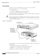
... IDSL router. • Any yellow Ethernet port on the router. Set HUB/NO HUB or TO HUB/TO PC button. Connect cable to the yellow ports on Cisco 803, 804, or 804 IDSL router. If applicable, check setting of hub equivalent of cable to an NT1. Figure 2-1 Connecting a Hub 1. Cisco 800 Series Routers Hardware Installation Guide 2-8 78-5373-04 This figure shows a Cisco 803 router with four Ethernet ports. To verify your router. If the LED is...
... IDSL router. • Any yellow Ethernet port on the router. Set HUB/NO HUB or TO HUB/TO PC button. Connect cable to the yellow ports on Cisco 803, 804, or 804 IDSL router. If applicable, check setting of hub equivalent of cable to an NT1. Figure 2-1 Connecting a Hub 1. Cisco 800 Series Routers Hardware Installation Guide 2-8 78-5373-04 This figure shows a Cisco 803 router with four Ethernet ports. To verify your router. If the LED is...
Hardware Installation Guide
Page 31
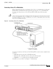
... panel. • ETHERNET 1, 2, 3, or 4 LED on the router. Connecting the cable to a Cisco 800 series ISDN or IDSL router, follow the steps in Chapter 3, "Troubleshooting." 78-5373-04 Cisco 800 Series Routers Hardware Installation Guide 2-9 Set HUB/NO HUB or TO HUB/TO PC button. PC ETH SER 0 OK LAN 11675 AUX 3. Figure 2-2 Connecting a Server, PC, or Workstation 1. Ensure that one of the following LEDs is not on Cisco 803, Cisco 804, or Cisco 804 IDSL router. Connect cable...
... panel. • ETHERNET 1, 2, 3, or 4 LED on the router. Connecting the cable to a Cisco 800 series ISDN or IDSL router, follow the steps in Chapter 3, "Troubleshooting." 78-5373-04 Cisco 800 Series Routers Hardware Installation Guide 2-9 Set HUB/NO HUB or TO HUB/TO PC button. PC ETH SER 0 OK LAN 11675 AUX 3. Figure 2-2 Connecting a Server, PC, or Workstation 1. Ensure that one of the following LEDs is not on Cisco 803, Cisco 804, or Cisco 804 IDSL router. Connect cable...
Hardware Installation Guide
Page 42
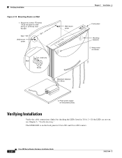
Place power supply on the back panel of Cisco 801 and Cisco 802 routers. 2-20 Cisco 800 Series Routers Hardware Installation Guide 78-5373-04 Secure two screws 7 5 8 inches (19.35 cm) apart in a wall and 1 8 in. (0.32 cm) from the wall. 758 in. (19.35 cm) Wall Wall-mount screw Wall-mount screw Wall 1 8 in Table 2-4. Verifying Installation Verify the cable connections (links) by checking the LEDs listed in . (0.32 cm) Screw Maximum...
Place power supply on the back panel of Cisco 801 and Cisco 802 routers. 2-20 Cisco 800 Series Routers Hardware Installation Guide 78-5373-04 Secure two screws 7 5 8 inches (19.35 cm) apart in a wall and 1 8 in. (0.32 cm) from the wall. 758 in. (19.35 cm) Wall Wall-mount screw Wall-mount screw Wall 1 8 in Table 2-4. Verifying Installation Verify the cable connections (links) by checking the LEDs listed in . (0.32 cm) Screw Maximum...

Hardware Installation Guide
Page 47
...; To make sure you have cabled the devices correctly, see Table 2-2 in parts of Europe, you have set buttons correctly, see Table 2-2 in Appendix B, "Specifications and Cables," to Cisco 801 and Cisco 803 Routers" section in the following tasks in Chapter 2, "Installation." 78-5373-04 Cisco 800 Series Routers Hardware Installation Guide 3-3 Damaged cable. • If you supply your Cisco reseller. No link to ISDN or IDSL network. (NT1, LINE, CH1, CH1 RXD, CH1 TXD, CH2...
...; To make sure you have cabled the devices correctly, see Table 2-2 in parts of Europe, you have set buttons correctly, see Table 2-2 in Appendix B, "Specifications and Cables," to Cisco 801 and Cisco 803 Routers" section in the following tasks in Chapter 2, "Installation." 78-5373-04 Cisco 800 Series Routers Hardware Installation Guide 3-3 Damaged cable. • If you supply your Cisco reseller. No link to ISDN or IDSL network. (NT1, LINE, CH1, CH1 RXD, CH1 TXD, CH2...

Hardware Installation Guide
Page 64
... you use to connect an Ethernet device. GL-2 Cisco 800 Series Routers Hardware Installation Guide 78-5373-04 F Flash memory The nonvolatile storage that can be electrically erased and reprogrammed so that data can be stored, booted, and rewritten as an operator and a piece of this button determines the cable type (straight-through or crossover) that provides network communication capabilities to carry data, voice, and other source traffic...
... you use to connect an Ethernet device. GL-2 Cisco 800 Series Routers Hardware Installation Guide 78-5373-04 F Flash memory The nonvolatile storage that can be electrically erased and reprogrammed so that data can be stored, booted, and rewritten as an operator and a piece of this button determines the cable type (straight-through or crossover) that provides network communication capabilities to carry data, voice, and other source traffic...
Hardware Installation Guide
Page 69
...router 2-4, ?? Index S S/T interface A-1 safety warnings 2-2 server, connecting 2-9 settings, network devices 2-6 to 2-7 specifications cabling B-6 system B-1 startup problems 3-2 T table mounting 2-18 telephone connecting 2-14, 2-15 ports described 1-2 illustrated 1-5, 1-6 temperature specifications B-1 terminal, connecting 2-17 TO HUB/TO PC button illustrated 1-6 to 1-7 settings 2-6 to 2-20 warnings, installation 2-2 weight specifications B-1 workstation, connecting 2-9 U U interface A-1 United Kingdom master sockets 2-16 78-5373-04 Cisco 800 Series Routers Hardware Installation Guide...
...router 2-4, ?? Index S S/T interface A-1 safety warnings 2-2 server, connecting 2-9 settings, network devices 2-6 to 2-7 specifications cabling B-6 system B-1 startup problems 3-2 T table mounting 2-18 telephone connecting 2-14, 2-15 ports described 1-2 illustrated 1-5, 1-6 temperature specifications B-1 terminal, connecting 2-17 TO HUB/TO PC button illustrated 1-6 to 1-7 settings 2-6 to 2-20 warnings, installation 2-2 weight specifications B-1 workstation, connecting 2-9 U U interface A-1 United Kingdom master sockets 2-16 78-5373-04 Cisco 800 Series Routers Hardware Installation Guide...


