
Installation Guide
Page 6
Chapter 2 Ethernet Ports 1-22 Line Cards 1-22 Alarm Card 1-23 Switch Fabric 1-25 Power Supplies 1-28 AC-Input Power Supply 1-29 DC-Input power Supply 1-30 Power Distribution 1-32 Blower Module 1-34 Air Filter...10 Power Guidelines 2-11 AC-Powered Systems 2-12 DC-Powered Systems 2-14 System Grounding Connection Guidelines 2-15 Site Wiring Guidelines 2-15 SONET Connection Guidelines 2-16 Power Budget 2-17 Approximating the Line Card Power Margin 2-18 Multimode Power Budget Example with Sufficient Power for Transmission 2-20 vi Cisco 12012 Gigabit Switch Router Installation and Configuration Guide
Chapter 2 Ethernet Ports 1-22 Line Cards 1-22 Alarm Card 1-23 Switch Fabric 1-25 Power Supplies 1-28 AC-Input Power Supply 1-29 DC-Input power Supply 1-30 Power Distribution 1-32 Blower Module 1-34 Air Filter...10 Power Guidelines 2-11 AC-Powered Systems 2-12 DC-Powered Systems 2-14 System Grounding Connection Guidelines 2-15 Site Wiring Guidelines 2-15 SONET Connection Guidelines 2-16 Power Budget 2-17 Approximating the Line Card Power Margin 2-18 Multimode Power Budget Example with Sufficient Power for Transmission 2-20 vi Cisco 12012 Gigabit Switch Router Installation and Configuration Guide
Installation Guide
Page 7
... SONET Single-Mode Power Budget Example 2-21 Using Statistics to Estimate the Power Budget 2-22 Tools for Installation 2-22 Unpacking the Cisco 12012 2-23 Checking the Shipping Packaging Contents 2-23 Site Log 2-24 Installing a Cisco 12012 3-1 Installing the Brace Bar 3-3 Removing the Cisco 12012 Components before Installing the Frame 3-4 Removing the Blower Modules 3-5 Removing Cards from the Card Cage...
... SONET Single-Mode Power Budget Example 2-21 Using Statistics to Estimate the Power Budget 2-22 Tools for Installation 2-22 Unpacking the Cisco 12012 2-23 Checking the Shipping Packaging Contents 2-23 Site Log 2-24 Installing a Cisco 12012 3-1 Installing the Brace Bar 3-3 Removing the Cisco 12012 Components before Installing the Frame 3-4 Removing the Blower Modules 3-5 Removing Cards from the Card Cage...

Installation Guide
Page 8
...4-1 Checking Connections in Preparation for System Startup 4-2 Starting the System and Observing Initial Conditions 4-3 Manually Booting the System 4-7 Configuring the Cisco 12012 4-8 Performing a Basic Manual Configuration Using the Setup Facility or the setup Command 4-8 Configuring the Global Parameters 4-9 Configuring Interfaces 4-15 ... 4-27 Configuration Register Bit Meanings 4-28 Recovering a Lost Password 4-31 Using Flash Memory Cards in the RP 4-34 Installing and Removing the Flash Memory Card in a RP 4-34 viii Cisco 12012 Gigabit Switch Router Installation and Configuration Guide
...4-1 Checking Connections in Preparation for System Startup 4-2 Starting the System and Observing Initial Conditions 4-3 Manually Booting the System 4-7 Configuring the Cisco 12012 4-8 Performing a Basic Manual Configuration Using the Setup Facility or the setup Command 4-8 Configuring the Global Parameters 4-9 Configuring Interfaces 4-15 ... 4-27 Configuration Register Bit Meanings 4-28 Recovering a Lost Password 4-31 Using Flash Memory Cards in the RP 4-34 Installing and Removing the Flash Memory Card in a RP 4-34 viii Cisco 12012 Gigabit Switch Router Installation and Configuration Guide
Installation Guide
Page 9
... 5-4 Troubleshooting the Power Subsystem 5-7 Troubleshooting the Processor Subsystem 5-9 Troubleshooting the RP 5-10 Troubleshooting the Line Cards 5-12 Troubleshooting Using the Alarm Card 5-14 Troubleshooting the Cooling Subsystem 5-15 Additional Reference Information for Troubleshooting 5-17 Running Diagnostics on the Cisco 12012 6-1 Diagnostic Test Overview 6-1 Using the diag Command 6-3 Diagnostic Testing Sequence 6-4 Loading and Running Diagnostics...
... 5-4 Troubleshooting the Power Subsystem 5-7 Troubleshooting the Processor Subsystem 5-9 Troubleshooting the RP 5-10 Troubleshooting the Line Cards 5-12 Troubleshooting Using the Alarm Card 5-14 Troubleshooting the Cooling Subsystem 5-15 Additional Reference Information for Troubleshooting 5-17 Running Diagnostics on the Cisco 12012 6-1 Diagnostic Test Overview 6-1 Using the diag Command 6-3 Diagnostic Testing Sequence 6-4 Loading and Running Diagnostics...

Installation Guide
Page 10
... Alarm Card from the Upper Card Cage 7-37 Removing the Cards from the Lower Card Cage 7-38 Removing the System Grounding 7-38 Removing the Card Cage Assembly 7-39 Installing a New Card Cage Assembly 7-39 Replacing the Cards in the Lower Card Cage 7-40 Replacing the Cards in the Upper Card Cage 7-40 Reattaching the System Grounding 7-41 x Cisco 12012 Gigabit Switch Router Installation...
... Alarm Card from the Upper Card Cage 7-37 Removing the Cards from the Lower Card Cage 7-38 Removing the System Grounding 7-38 Removing the Card Cage Assembly 7-39 Installing a New Card Cage Assembly 7-39 Replacing the Cards in the Lower Card Cage 7-40 Replacing the Cards in the Upper Card Cage 7-40 Reattaching the System Grounding 7-41 x Cisco 12012 Gigabit Switch Router Installation...

Installation Guide
Page 11
... Processor 7-42 Removing and Replacing an Alarm Card 7-43 Removing and Replacing a Clock and Scheduler Card or Switch Fabric Card 7-45 Upgrading RP and Line Card Memory 7-45 Repackaging the Cisco 12012 A-1 Tools Required A-2 Safety Recommendations A-2 Removing the Cisco 12012 from a Rack A-3 Powering Down the Cisco 12012 A-3 Removing the Blower Modules A-3 Removing the Card Cage Assembly A-3 Removing the Frame from the...
... Processor 7-42 Removing and Replacing an Alarm Card 7-43 Removing and Replacing a Clock and Scheduler Card or Switch Fabric Card 7-45 Upgrading RP and Line Card Memory 7-45 Repackaging the Cisco 12012 A-1 Tools Required A-2 Safety Recommendations A-2 Removing the Cisco 12012 from a Rack A-3 Powering Down the Cisco 12012 A-3 Removing the Blower Modules A-3 Removing the Card Cage Assembly A-3 Removing the Frame from the...
Installation Guide
Page 13
...) 1-8 Performance Route Processor (Front Panel View, Horizontal Orientation Shown) 1-14 PRP (Horizontal Orientation) 1-16 Alarm Card Faceplate LEDs, Switches, and Connectors 1-25 Lower Card Cage 1-26 AC-Input Power Supply 1-30 DC-Input Power Supply 1-32 Cisco 12012 Power Distribution 1-33 Blower Module (Shown without the Blower Module Front Cover) 1-34 Internal Air Flow...
...) 1-8 Performance Route Processor (Front Panel View, Horizontal Orientation Shown) 1-14 PRP (Horizontal Orientation) 1-16 Alarm Card Faceplate LEDs, Switches, and Connectors 1-25 Lower Card Cage 1-26 AC-Input Power Supply 1-30 DC-Input Power Supply 1-32 Cisco 12012 Power Distribution 1-33 Blower Module (Shown without the Blower Module Front Cover) 1-34 Internal Air Flow...
Installation Guide
Page 14
... Hole Groups 3-20 Installing the Frame in the Rack 3-22 Attaching an Interface Cable to a Line Card 3-32 Console and Auxiliary Port Connections 3-33 RJ-45 and MII Ethernet Connections 3-37 Ethernet MII Receptacle... (Connecting MDI Ethernet Port to MDI-X Wiring) 3-46 Crossover Cable Pinout (for Connecting Two PRPs) 3-46 Alarm Card Connectors 3-48 System Grounding Receptacles 3-51 Attaching a Grounding Lug to the Grounding Receptacles 3-52 Connecting Source AC to... RP Alphanumeric LED Displays (Partial Front Panel View) 4-3 xiv Cisco 12012 Gigabit Switch Router Installation and Configuration Guide
... Hole Groups 3-20 Installing the Frame in the Rack 3-22 Attaching an Interface Cable to a Line Card 3-32 Console and Auxiliary Port Connections 3-33 RJ-45 and MII Ethernet Connections 3-37 Ethernet MII Receptacle... (Connecting MDI Ethernet Port to MDI-X Wiring) 3-46 Crossover Cable Pinout (for Connecting Two PRPs) 3-46 Alarm Card Connectors 3-48 System Grounding Receptacles 3-51 Attaching a Grounding Lug to the Grounding Receptacles 3-52 Connecting Source AC to... RP Alphanumeric LED Displays (Partial Front Panel View) 4-3 xiv Cisco 12012 Gigabit Switch Router Installation and Configuration Guide

Installation Guide
Page 15
...Figure 7-9 Figure 7-10 Figure 7-11 Figure 7-12 Figure 7-13 Figure 7-14 Figure 7-15 Figure A-1 Figure A-2 Installing and Removing a Flash Memory Card 4-36 Connecting an ESD-Preventive Strap to the Cisco 12012 7-4 Removing the Air Filter 7-6 Removing the Screws from the Old Air Filter Tray 7-8 New Air Filter Hinge Holes and Chassis Holes...DC-Input Power Supply 7-24 DC Power Cable Lug 7-26 Installing a DC-Input Power Supply 7-29 Removing the Interface Cables from a Line Card 7-36 Removing an Alarm Card 7-44 Removing the Frame from the Rack A-5 Cisco 12012 Shipping Packaging A-9 List of Figures xv
...Figure 7-9 Figure 7-10 Figure 7-11 Figure 7-12 Figure 7-13 Figure 7-14 Figure 7-15 Figure A-1 Figure A-2 Installing and Removing a Flash Memory Card 4-36 Connecting an ESD-Preventive Strap to the Cisco 12012 7-4 Removing the Air Filter 7-6 Removing the Screws from the Old Air Filter Tray 7-8 New Air Filter Hinge Holes and Chassis Holes...DC-Input Power Supply 7-24 DC Power Cable Lug 7-26 Installing a DC-Input Power Supply 7-29 Removing the Interface Cables from a Line Card 7-36 Removing an Alarm Card 7-44 Removing the Frame from the Rack A-5 Cisco 12012 Shipping Packaging A-9 List of Figures xv
Installation Guide
Page 18
...-Mbps Transmission 3-47 IEEE 802.3u Physical Characteristics 3-47 Alarm 1 and Alarm 2 Connector Pinout 3-49 RP Alphanumeric LED Display Sequences 4-4 Line Card Alphanumeric LED Display Sequences 4-4 Software Configuration Register Bit Meanings 4-25 Explanation of Boot Field (Configuration Register Bits 00 to 03) 4-25 Default Boot... for Broadcast Address Destination 4-30 System Console Terminal Transmission Rate Settings 4-30 RP Alphanumeric LED Display Messages 5-10 Line Card Alphanumeric LED Display Messages 5-13 xviii Cisco 12012 Gigabit Switch Router Installation and Configuration Guide
...-Mbps Transmission 3-47 IEEE 802.3u Physical Characteristics 3-47 Alarm 1 and Alarm 2 Connector Pinout 3-49 RP Alphanumeric LED Display Sequences 4-4 Line Card Alphanumeric LED Display Sequences 4-4 Software Configuration Register Bit Meanings 4-25 Explanation of Boot Field (Configuration Register Bits 00 to 03) 4-25 Default Boot... for Broadcast Address Destination 4-30 System Console Terminal Transmission Rate Settings 4-30 RP Alphanumeric LED Display Messages 5-10 Line Card Alphanumeric LED Display Messages 5-13 xviii Cisco 12012 Gigabit Switch Router Installation and Configuration Guide
Installation Guide
Page 25
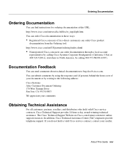
... Headquarters (California, USA) at this URL: http://www.cisco.com/univercd/cc/td/doc/es_inpck/pdi.htm You can order Cisco documentation in North America, by calling 800 553-NETS (6387). You can submit comments by using the response card (if present) behind the front cover of your document ...or by writing to bug-doc@cisco.com. If you do not hold valid Cisco service contracts, Cisco Technical Support provides 24-hour-a-day, award-winning technical assistance. About ...
... Headquarters (California, USA) at this URL: http://www.cisco.com/univercd/cc/td/doc/es_inpck/pdi.htm You can order Cisco documentation in North America, by calling 800 553-NETS (6387). You can submit comments by using the response card (if present) behind the front cover of your document ...or by writing to bug-doc@cisco.com. If you do not hold valid Cisco service contracts, Cisco Technical Support provides 24-hour-a-day, award-winning technical assistance. About ...
Installation Guide
Page 29
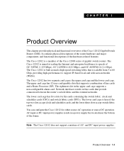
... line cards that is keyed; It contains physical descriptions of the router hardware and major components, and functional descriptions of line cards and a Route Processor (RP). the upper card cage and the lower card cage. The lower card cage is scalable from 5 to 60 Gbps,...source DC operation. The Cisco 12012 is a member of the Cisco 12000 series of the Cisco 12012 Gigabit Switch Router (GSR). You can configure the Cisco 12012 for the cards containing the switch fabric: clock and scheduler cards (CSCs) and switch fabric cards (SFCs). The Cisco 12012 is aimed at scaling ...
... line cards that is keyed; It contains physical descriptions of the router hardware and major components, and functional descriptions of line cards and a Route Processor (RP). the upper card cage and the lower card cage. The lower card cage is scalable from 5 to 60 Gbps,...source DC operation. The Cisco 12012 is a member of the Cisco 12000 series of the Cisco 12012 Gigabit Switch Router (GSR). You can configure the Cisco 12012 for the cards containing the switch fabric: clock and scheduler cards (CSCs) and switch fabric cards (SFCs). The Cisco 12012 is aimed at scaling ...
Installation Guide
Page 30
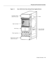
... that mounts in the frame support the other three major components: a card cage assembly and two blower modules. All three components are tied together electrically through a passive system backplane in the card cage. 1-2 Cisco 12012 Gigabit Switch Router Installation and Configuration Guide The upper card cage has 12 vertical slots for the switch fabric. Physical and...
... that mounts in the frame support the other three major components: a card cage assembly and two blower modules. All three components are tied together electrically through a passive system backplane in the card cage. 1-2 Cisco 12012 Gigabit Switch Router Installation and Configuration Guide The upper card cage has 12 vertical slots for the switch fabric. Physical and...
Installation Guide
Page 31
...Overviews Figure 1-1 Cisco 12012 (Front View, AC-Input Power Supplies Shown) Top blower module (behind front cover) Frame 0 ACTIVCEARRRIXERPKT EJECT SSLLOOTT--01 RESET AUX 1 ACTIVCEARRRIXERCELL 0 ACTIVCEARRRIXERCELL 0 CRITICALMAJORMINOR ACTIVCEARRRIXERPKT 2 CONSOLE ALARM 1 ACO/LT ACTIVCEARRRIXERPKT 3 ACTIVCEARRRIXERPKT COLL RX LINK TX Upper card cage RJ-...behind front cover) ~ INPUT: 200 -240V 10 A 50/60 HZ 2000 W ~ INPUT: 200 -240V 10 A 50/60 HZ 2000 W ~ INPUT: 200 -240V 10 A 50/60 HZ 2000 W ~ INPUT: 200 -240V 10 A 50/60 HZ 2000 W AC OK OUTPUT FAIL AC OK OUTPUT FAIL...
...Overviews Figure 1-1 Cisco 12012 (Front View, AC-Input Power Supplies Shown) Top blower module (behind front cover) Frame 0 ACTIVCEARRRIXERPKT EJECT SSLLOOTT--01 RESET AUX 1 ACTIVCEARRRIXERCELL 0 ACTIVCEARRRIXERCELL 0 CRITICALMAJORMINOR ACTIVCEARRRIXERPKT 2 CONSOLE ALARM 1 ACO/LT ACTIVCEARRRIXERPKT 3 ACTIVCEARRRIXERPKT COLL RX LINK TX Upper card cage RJ-...behind front cover) ~ INPUT: 200 -240V 10 A 50/60 HZ 2000 W ~ INPUT: 200 -240V 10 A 50/60 HZ 2000 W ~ INPUT: 200 -240V 10 A 50/60 HZ 2000 W ~ INPUT: 200 -240V 10 A 50/60 HZ 2000 W AC OK OUTPUT FAIL AC OK OUTPUT FAIL...
Installation Guide
Page 32
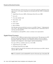
... support, and line card monitoring. The RP also performs general maintenance functions, such as the primary RP. 1-4 Cisco 12012 Gigabit Switch Router Installation and Configuration Guide Chapter 7, "Maintaining the Cisco 12012," and separate documents called configuration notes contain instructions for the Cisco 12012 GSR: • .... Note If you install a second, redundant RP, it must be of the Cisco 12012 provides access to all system components, making the system easy to the Cisco Express Forwarding (CEF) tables on ordering FRUs, contact a customer service representative. All...
... support, and line card monitoring. The RP also performs general maintenance functions, such as the primary RP. 1-4 Cisco 12012 Gigabit Switch Router Installation and Configuration Guide Chapter 7, "Maintaining the Cisco 12012," and separate documents called configuration notes contain instructions for the Cisco 12012 GSR: • .... Note If you install a second, redundant RP, it must be of the Cisco 12012 provides access to all system components, making the system easy to the Cisco Express Forwarding (CEF) tables on ordering FRUs, contact a customer service representative. All...
Installation Guide
Page 33
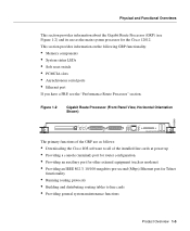
... Figure 1-2) and its use as modems) • Providing an IEEE 802.3, 10/100-megabits-per-second (Mbps) Ethernet port for the Cisco 12012. Figure 1-2 Gigabit Route Processor (Front Panel View, Horizontal Orientation Shown) H10548 EJECT SSLLOOTT--01 RESET AUX CONSOLE COLL RX LINK TX RJ-45... PROCESSOR The primary functions of the GRP are as follows: • Downloading the Cisco IOS software to all of the installed line cards at power up • Providing a console (terminal) port for router configuration • Providing an auxiliary port for other external equipment (such as the...
... Figure 1-2) and its use as modems) • Providing an IEEE 802.3, 10/100-megabits-per-second (Mbps) Ethernet port for the Cisco 12012. Figure 1-2 Gigabit Route Processor (Front Panel View, Horizontal Orientation Shown) H10548 EJECT SSLLOOTT--01 RESET AUX CONSOLE COLL RX LINK TX RJ-45... PROCESSOR The primary functions of the GRP are as follows: • Downloading the Cisco IOS software to all of the installed line cards at power up • Providing a console (terminal) port for router configuration • Providing an auxiliary port for other external equipment (such as the...
Installation Guide
Page 34
...to remotely download, store, and boot from software images resident in -line memory module (SIMM), and on two, 60-nanosecond (ns), dual in-line memory modules (DIMMs); 64 MB of DRAM is the minimum shipping configuration. •...Cisco IOS image. 1-6 Cisco 12012 Gigabit Switch Router Installation and Configuration Guide The Cisco 12012 supports downloadable system software for packets that insert in the two PCMCIA slots (slot 0 and slot 1) on the GRP in the form of the GRP. (See Figure 1-2.) Storing the Cisco IOS images in Flash memory enables you to two Personal Computer Memory Card...
...to remotely download, store, and boot from software images resident in -line memory module (SIMM), and on two, 60-nanosecond (ns), dual in-line memory modules (DIMMs); 64 MB of DRAM is the minimum shipping configuration. •...Cisco IOS image. 1-6 Cisco 12012 Gigabit Switch Router Installation and Configuration Guide The Cisco 12012 supports downloadable system software for packets that insert in the two PCMCIA slots (slot 0 and slot 1) on the GRP in the form of the GRP. (See Figure 1-2.) Storing the Cisco IOS images in Flash memory enables you to two Personal Computer Memory Card...
Installation Guide
Page 35
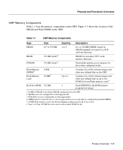
NVRAM is the default shipping configuration for the Cisco 12012. 6. SRAM for main Cisco IOS software functions. Product Overview 1-7 Flash Memory (SIMM)4 Flash Memory (card) 8 MB 20 MB5 1 Up to 2 Contains Cisco IOS software images and other user-defined files on up to 256 MB Quantity 1 or 2 512 KB (...or field upgradeable. 3. or 128-MB DIMMs (based on the GRP. Type 1 or Type 2 PCMCIA cards can be used in either PCMCIA slot. Contains Cisco IOS software images and other user-defined files on DRAM required) for secondary CPU cache memory functions. Nonvolatile ...
NVRAM is the default shipping configuration for the Cisco 12012. 6. SRAM for main Cisco IOS software functions. Product Overview 1-7 Flash Memory (SIMM)4 Flash Memory (card) 8 MB 20 MB5 1 Up to 2 Contains Cisco IOS software images and other user-defined files on up to 256 MB Quantity 1 or 2 512 KB (...or field upgradeable. 3. or 128-MB DIMMs (based on the GRP. Type 1 or Type 2 PCMCIA cards can be used in either PCMCIA slot. Contains Cisco IOS software images and other user-defined files on DRAM required) for secondary CPU cache memory functions. Nonvolatile ...
Installation Guide
Page 37
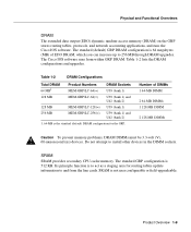
...1 64-MB DIMM 2 64-MB DIMMs 1 128-MB DIMM 2 128-MB DIMMs Caution To prevent memory problems, DRAM DIMMs must be 3.3-volt (V), 60-nanosecond (ns) devices. Number of EDO DRAM, which you can increase up to 256 MB through DRAM upgrades. SRAM is 512 KB. Product Overview 1-9... The Cisco IOS software runs from the line cards. Table 1-2 lists the DRAM configurations and upgrades. SRAM SRAM provides secondary CPU cache memory. Physical and Functional Overviews DRAM The...
...1 64-MB DIMM 2 64-MB DIMMs 1 128-MB DIMM 2 128-MB DIMMs Caution To prevent memory problems, DRAM DIMMs must be 3.3-volt (V), 60-nanosecond (ns) devices. Number of EDO DRAM, which you can increase up to 256 MB through DRAM upgrades. SRAM is 512 KB. Product Overview 1-9... The Cisco IOS software runs from the line cards. Table 1-2 lists the DRAM configurations and upgrades. SRAM SRAM provides secondary CPU cache memory. Physical and Functional Overviews DRAM The...
Installation Guide
Page 38
...or to reenter the entire configuration manually. The LEDs indicate link activity, collision detection, data transmission, and data reception. 1-10 Cisco 12012 Gigabit Switch Router Installation and Configuration Guide Flash memory also functions as a TFTP server to allow you are temporarily removing a GRP; Two PCMCIA ...can download a new image over the network or from the switched slot voltage. - Flash Memory Both the onboard and PCMCIA card-based Flash memory allow other servers to Flash memory or replace the existing files. You can retrieve it later. System Status LEDs...
...or to reenter the entire configuration manually. The LEDs indicate link activity, collision detection, data transmission, and data reception. 1-10 Cisco 12012 Gigabit Switch Router Installation and Configuration Guide Flash memory also functions as a TFTP server to allow you are temporarily removing a GRP; Two PCMCIA ...can download a new image over the network or from the switched slot voltage. - Flash Memory Both the onboard and PCMCIA card-based Flash memory allow other servers to Flash memory or replace the existing files. You can retrieve it later. System Status LEDs...
