
Installation Guide
Page 29
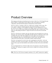
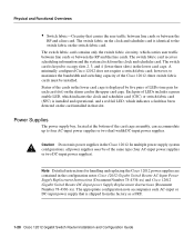
...reside on line cards that support a combination of gigabit switch routers. You can configure the Cisco 12012 for the cards containing the switch fabric: clock and scheduler cards (CSCs) and switch fabric cards (SFCs). Product Overview 1-1 The Cisco 12012 is built around a high-speed switching fabric that is ...and DC-input power supplies. The lower card cage is scalable from 5 to 60 Gbps, providing high-performance to speeds of AC- The Cisco 12012 has two separate card cages; The Cisco 12012 is aimed at scaling the Internet and enterprise backbones to support IP-based local and...
...reside on line cards that support a combination of gigabit switch routers. You can configure the Cisco 12012 for the cards containing the switch fabric: clock and scheduler cards (CSCs) and switch fabric cards (SFCs). Product Overview 1-1 The Cisco 12012 is built around a high-speed switching fabric that is ...and DC-input power supplies. The lower card cage is scalable from 5 to 60 Gbps, providing high-performance to speeds of AC- The Cisco 12012 has two separate card cages; The Cisco 12012 is aimed at scaling the Internet and enterprise backbones to support IP-based local and...
Installation Guide
Page 31
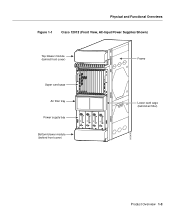
Physical and Functional Overviews Figure 1-1 Cisco 12012 (Front View, AC-Input Power Supplies Shown) Top blower module (behind front cover) Frame 0 ACTIVCEARRRIXERPKT EJECT SSLLOOTT--01 RESET AUX 1 ACTIVCEARRRIXERCELL 0 ACTIVCEARRRIXERCELL 0 CRITICALMAJORMINOR ACTIVCEARRRIXERPKT 2 CONSOLE ... 2000 W ~ INPUT: 200 -240V 10 A 50/60 HZ 2000 W ~ INPUT: 200 -240V 10 A 50/60 HZ 2000 W ~ INPUT: 200 -240V 10 A 50/60 HZ 2000 W AC OK OUTPUT FAIL AC OK OUTPUT FAIL AC OK OUTPUT FAIL AC OK OUTPUT FAIL SFC 12 ALARM CSC 10 FAIL ENABLED 0 ALARM 2 Lower card cage (behind air...
Physical and Functional Overviews Figure 1-1 Cisco 12012 (Front View, AC-Input Power Supplies Shown) Top blower module (behind front cover) Frame 0 ACTIVCEARRRIXERPKT EJECT SSLLOOTT--01 RESET AUX 1 ACTIVCEARRRIXERCELL 0 ACTIVCEARRRIXERCELL 0 CRITICALMAJORMINOR ACTIVCEARRRIXERPKT 2 CONSOLE ... 2000 W ~ INPUT: 200 -240V 10 A 50/60 HZ 2000 W ~ INPUT: 200 -240V 10 A 50/60 HZ 2000 W ~ INPUT: 200 -240V 10 A 50/60 HZ 2000 W AC OK OUTPUT FAIL AC OK OUTPUT FAIL AC OK OUTPUT FAIL AC OK OUTPUT FAIL SFC 12 ALARM CSC 10 FAIL ENABLED 0 ALARM 2 Lower card cage (behind air...
Installation Guide
Page 53
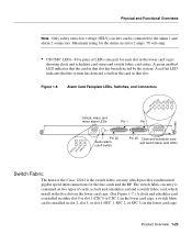
... 1 H10900 CRITICALMAJORMINOR CRITICALMAJORMINOR ALARM 1 ACO/LT Pin 25 Audio alarm cutoff switch ALARM 2 CSC SFC FAIL ENABLED 0 1 0 12 ALARM Pin 25 Clock and scheduler card and switch fabric card LEDs Switch Fabric The heart of the Cisco 12012 is the switch fabric circuity, which install in the five slots in the lower card...
... 1 H10900 CRITICALMAJORMINOR CRITICALMAJORMINOR ALARM 1 ACO/LT Pin 25 Audio alarm cutoff switch ALARM 2 CSC SFC FAIL ENABLED 0 1 0 12 ALARM Pin 25 Clock and scheduler card and switch fabric card LEDs Switch Fabric The heart of the Cisco 12012 is the switch fabric circuity, which install in the five slots in the lower card...
Installation Guide
Page 54
... OC-12/STM-4 ATM Q OC-3/STM-POS GIGABIT ROUTE PROCESSOR CSC 10 SFC 12 ALARM Lower card cage slot 0 Lower card cage slot 4 H11017 1-26 Cisco 12012 Gigabit Switch Router Installation and Configuration Guide You can add switching capacity (up to 60 Gbps) and redundancy by increasing the number of switch cards (to operate. Physical...
... OC-12/STM-4 ATM Q OC-3/STM-POS GIGABIT ROUTE PROCESSOR CSC 10 SFC 12 ALARM Lower card cage slot 0 Lower card cage slot 4 H11017 1-26 Cisco 12012 Gigabit Switch Router Installation and Configuration Guide You can add switching capacity (up to 60 Gbps) and redundancy by increasing the number of switch cards (to operate. Physical...
Installation Guide
Page 56
... and the line cards. The switch fabric card receives scheduling information and the system clock from the factory as a FRU. 1-28 Cisco 12012 Gigabit Switch Router Installation and Configuration Guide The switch card is keyed to the switch fabric on the card installed in the upper card cage. Status...lower card cage is installed and operational, and a red fail LED, which indicates the clock and scheduler card (CSC) or switch fabric card (SFC) is displayed by five pairs of LEDs includes a green enable LED, which indicates a fault has been detected on the switch fabric card. Each...
... and the line cards. The switch fabric card receives scheduling information and the system clock from the factory as a FRU. 1-28 Cisco 12012 Gigabit Switch Router Installation and Configuration Guide The switch card is keyed to the switch fabric on the card installed in the upper card cage. Status...lower card cage is installed and operational, and a red fail LED, which indicates the clock and scheduler card (CSC) or switch fabric card (SFC) is displayed by five pairs of LEDs includes a green enable LED, which indicates a fault has been detected on the switch fabric card. Each...
Installation Guide
Page 66
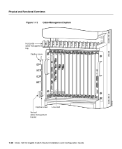
H10733 CRITICALMAJORMINOR ALARM 1 ACO/LT ALARM 2 FAIL ENABLED 0 CSC 10 SFC 12 ALARM 1-38 Cisco 12012 Gigabit Switch Router Installation and Configuration Guide Line card Captive screw Vertical cable-management bracket Physical and Functional Overviews Figure 1-13 Cable-Management System Horizontal cable-management tray ...
H10733 CRITICALMAJORMINOR ALARM 1 ACO/LT ALARM 2 FAIL ENABLED 0 CSC 10 SFC 12 ALARM 1-38 Cisco 12012 Gigabit Switch Router Installation and Configuration Guide Line card Captive screw Vertical cable-management bracket Physical and Functional Overviews Figure 1-13 Cable-Management System Horizontal cable-management tray ...
Installation Guide
Page 101
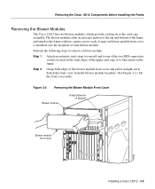
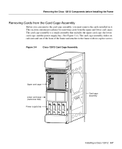
...-12/STM-4 POS OC-12/STM-4 ATM Q OC-3/STM-POS ROUTE PROCESSOR CSC 10 SFC 12 ALARM Installing a Cisco 12012 3-5 A snap-on the front edges of each . Removing the Cisco 12012 Components before Installing the Frame Removing the Blower Modules The Cisco 12012 has two blower modules, which provide cooling air to the frame with two captive...
...-12/STM-4 POS OC-12/STM-4 ATM Q OC-3/STM-POS ROUTE PROCESSOR CSC 10 SFC 12 ALARM Installing a Cisco 12012 3-5 A snap-on the front edges of each . Removing the Cisco 12012 Components before Installing the Frame Removing the Blower Modules The Cisco 12012 has two blower modules, which provide cooling air to the frame with two captive...
Installation Guide
Page 102
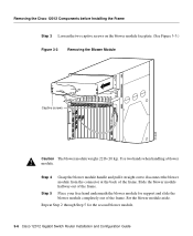
... back of the frame. Step 5 Place your free hand underneath the blower module for the second blower module. 3-6 Cisco 12012 Gigabit Switch Router Installation and Configuration Guide Removing the Cisco 12012 Components before Installing the Frame Step 3 Loosen the two captive screws on the blower module faceplate. (See Figure 3-3.) ...H10655 RJ-45 MII ALARM 2 FAIL ENABLED 0 OC-12/STM-4 POS OC-12/STM-4 ATM Q OC-3/STM-POS ROUTE PROCESSOR CSC 10 SFC 12 ALARM Caution The blower module weighs 22 lb (10 kg). Use two hands when handling a blower module. Repeat Step 2 through Step 5...
... back of the frame. Step 5 Place your free hand underneath the blower module for the second blower module. 3-6 Cisco 12012 Gigabit Switch Router Installation and Configuration Guide Removing the Cisco 12012 Components before Installing the Frame Step 3 Loosen the two captive screws on the blower module faceplate. (See Figure 3-3.) ...H10655 RJ-45 MII ALARM 2 FAIL ENABLED 0 OC-12/STM-4 POS OC-12/STM-4 ATM Q OC-3/STM-POS ROUTE PROCESSOR CSC 10 SFC 12 ALARM Caution The blower module weighs 22 lb (10 kg). Use two hands when handling a blower module. Repeat Step 2 through Step 5...
Installation Guide
Page 103
... 2000 W ~ INPUT: 200 -240V 10 A 50/60 HZ 2000 W ~ INPUT: 200 -240V 10 A 50/60 HZ 2000 W AC OK OUTPUT FAIL AC OK OUTPUT FAIL AC OK OUTPUT FAIL AC OK OUTPUT FAIL SFC 12 ALARM CSC 10 FAIL ENABLED 0 ALARM 2 Card cage assembly H10662 Installing a Cisco 12012 3-7 This section contains procedures for removing cards...
... 2000 W ~ INPUT: 200 -240V 10 A 50/60 HZ 2000 W ~ INPUT: 200 -240V 10 A 50/60 HZ 2000 W AC OK OUTPUT FAIL AC OK OUTPUT FAIL AC OK OUTPUT FAIL AC OK OUTPUT FAIL SFC 12 ALARM CSC 10 FAIL ENABLED 0 ALARM 2 Card cage assembly H10662 Installing a Cisco 12012 3-7 This section contains procedures for removing cards...
Installation Guide
Page 105
...MII ALARM 2 FAIL ENABLED 0 CSC 10 OC-12/STM-4 POS OC-12/STM-4 ATM Q OC-3/STM-POS GIGABIT ROUTE PROCESSOR COLL RX LINK TX SFC 12 ALARM RJ-45 MII H10704 GIGABIT ROUTE PROCESSOR b Pivot ejector levers away from the backplane connector. (See Figure 3-5b.) Grasp the card carrier edge... slide card out of slot Repeat Step 3 through Step 5 for the rest of the slot and place it immediately on the antistatic mat. Removing the Cisco 12012 Components before Installing the Frame Step 3 Step 4 Step 5 Starting from slot 0 (left side of the upper card cage), select a card and loosen the two...
...MII ALARM 2 FAIL ENABLED 0 CSC 10 OC-12/STM-4 POS OC-12/STM-4 ATM Q OC-3/STM-POS GIGABIT ROUTE PROCESSOR COLL RX LINK TX SFC 12 ALARM RJ-45 MII H10704 GIGABIT ROUTE PROCESSOR b Pivot ejector levers away from the backplane connector. (See Figure 3-5b.) Grasp the card carrier edge... slide card out of slot Repeat Step 3 through Step 5 for the rest of the slot and place it immediately on the antistatic mat. Removing the Cisco 12012 Components before Installing the Frame Step 3 Step 4 Step 5 Starting from slot 0 (left side of the upper card cage), select a card and loosen the two...
Installation Guide
Page 107
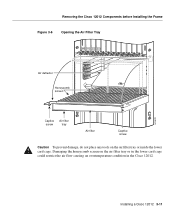
... filter tray or inside the lower card cage. Removing the Cisco 12012 Components before Installing the Frame Figure 3-6 Opening the Air Filter Tray FAIL ENABLED 0 OC-12/STM-4 POS OC-12/STM-4 ATM Q OC-3/STM-POS GIGABIT ROUTE PROCESSOR CSC 10 SFC 12 ALARM Air deflector Honeycomb screen H10472 Captive Air filter screw...
... filter tray or inside the lower card cage. Removing the Cisco 12012 Components before Installing the Frame Figure 3-6 Opening the Air Filter Tray FAIL ENABLED 0 OC-12/STM-4 POS OC-12/STM-4 ATM Q OC-3/STM-POS GIGABIT ROUTE PROCESSOR CSC 10 SFC 12 ALARM Air deflector Honeycomb screen H10472 Captive Air filter screw...
Installation Guide
Page 108
... ENABLED 0 OC-12/STM-4 POS OC-12/STM-4 ATM Q OC-3/STM-POS GIGABIT ROUTE PROCESSOR CSC 10 SFC 12 ALARM H10473 Air filter tray 3-12 Cisco 12012 Gigabit Switch Router Installation and Configuration Guide Removing the Cisco 12012 Components before Installing the Frame Step 3 To access the cards in the lower card cage, you must first...
... ENABLED 0 OC-12/STM-4 POS OC-12/STM-4 ATM Q OC-3/STM-POS GIGABIT ROUTE PROCESSOR CSC 10 SFC 12 ALARM H10473 Air filter tray 3-12 Cisco 12012 Gigabit Switch Router Installation and Configuration Guide Removing the Cisco 12012 Components before Installing the Frame Step 3 To access the cards in the lower card cage, you must first...

Installation Guide
Page 109
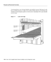
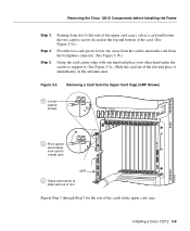
Grasp the two card ejector levers and simultaneously pivot both ejector levers 90 degrees away from the sides of the cards in the lower card cage. Removing the Cisco 12012 Components before Installing the Frame Step 4 Select one of the card cage to unseat the card from the backplane connector. (See Figure 3-8.) Figure 3-8 Removing Cards from the Lower Card Cage Card ejector lever Card ejector lever FAIL ENABLED 0 OC-12/STM-4 POS OC-12/STM-4 ATM Q OC-3/STM-POS GIGABIT ROUTE PROCESSOR CSC 10 SFC 12 ALARM Lower card cage Switch fabric card H10474 Installing a Cisco 12012 3-13
Grasp the two card ejector levers and simultaneously pivot both ejector levers 90 degrees away from the sides of the cards in the lower card cage. Removing the Cisco 12012 Components before Installing the Frame Step 4 Select one of the card cage to unseat the card from the backplane connector. (See Figure 3-8.) Figure 3-8 Removing Cards from the Lower Card Cage Card ejector lever Card ejector lever FAIL ENABLED 0 OC-12/STM-4 POS OC-12/STM-4 ATM Q OC-3/STM-POS GIGABIT ROUTE PROCESSOR CSC 10 SFC 12 ALARM Lower card cage Switch fabric card H10474 Installing a Cisco 12012 3-13
Installation Guide
Page 144
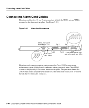
... SFC FAIL ENABLED 0 1 0 12 ALARM Pin 25 Clock and scheduler card and switch fabric card LEDs The alarm card connectors enable you to connect the Cisco 12012 to a site alarm maintenance system. Critical, major, and minor alarms generated in the Cisco 12012 system are accessible through the two alarm card connectors. 3-48 Cisco 12012 Gigabit Switch Router Installation...
... SFC FAIL ENABLED 0 1 0 12 ALARM Pin 25 Clock and scheduler card and switch fabric card LEDs The alarm card connectors enable you to connect the Cisco 12012 to a site alarm maintenance system. Critical, major, and minor alarms generated in the Cisco 12012 system are accessible through the two alarm card connectors. 3-48 Cisco 12012 Gigabit Switch Router Installation...
Installation Guide
Page 147
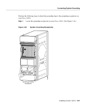
... following steps to attach the grounding lugs to the grounding receptacles on your Cisco 12012: Step 1 Locate the grounding receptacles on your Cisco 12012. (See Figure 3-24.) Figure 3-24 System Grounding Receptacles H10899 CRITICALMAJORMINOR ALARM 1 ACO/LT ALARM 2 FAIL ENABLED 0 CSC 10 SFC 12 ALARM System grounding receptacles ACTIVCEARRRIXERCELL 0 ACTIVCEARRRIXERCELL 0 ACTIVCEARRRIXERPKT ACTIVCEARRRIXERPKT ACTIVCEARRRIXERPKT ACTIVCEARRRIXERPKT 0 1 2 3 EJECT...
... following steps to attach the grounding lugs to the grounding receptacles on your Cisco 12012: Step 1 Locate the grounding receptacles on your Cisco 12012. (See Figure 3-24.) Figure 3-24 System Grounding Receptacles H10899 CRITICALMAJORMINOR ALARM 1 ACO/LT ALARM 2 FAIL ENABLED 0 CSC 10 SFC 12 ALARM System grounding receptacles ACTIVCEARRRIXERCELL 0 ACTIVCEARRRIXERCELL 0 ACTIVCEARRRIXERPKT ACTIVCEARRRIXERPKT ACTIVCEARRRIXERPKT ACTIVCEARRRIXERPKT 0 1 2 3 EJECT...
Installation Guide
Page 232
....0ST, the default download method changes from the mbus to pass traffic normally. Note You can use on operational, business-critical routers. If multiple cards are running, the line card being tested is controlled by default when an error is encountered. Diagnostics take ... cards (CSCs) and the switch fabric cards (SFCs), which may temporarily drop throughput on the card being tested; It takes about 1-minute to obtain test results from the mbus. The diagnostics affect just the line card being tested. 6-2 Cisco 12012 Gigabit Switch Router Installation and Configuration Guide
....0ST, the default download method changes from the mbus to pass traffic normally. Note You can use on operational, business-critical routers. If multiple cards are running, the line card being tested is controlled by default when an error is encountered. Diagnostics take ... cards (CSCs) and the switch fabric cards (SFCs), which may temporarily drop throughput on the card being tested; It takes about 1-minute to obtain test results from the mbus. The diagnostics affect just the line card being tested. 6-2 Cisco 12012 Gigabit Switch Router Installation and Configuration Guide
Installation Guide
Page 244
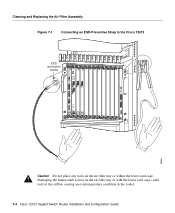
... lower card cage could restrict the airflow causing an overtemperature condition in the router. 7-4 Cisco 12012 Gigabit Switch Router Installation and Configuration Guide Connecting an ESD-Preventive Strap to the Cisco 12012 OOOOOOOOOOOOOOOOOOOOOOOOOOOOOOOOOOOOOOOOOOOOOOOOOOOOOOOOOOOOOOOOOOOOOOOOOOOOOOOOOOOOOOOOOOOOOO 46596 CRITICALMAJORMINOR ALARM 1 ACO/LT ALARM 2 FAIL ENABLED 0 CSC 10 SFC 12 ALARM ESD connection socket Figure 7-1 Cleaning and Replacing the Air Filter Assembly...
... lower card cage could restrict the airflow causing an overtemperature condition in the router. 7-4 Cisco 12012 Gigabit Switch Router Installation and Configuration Guide Connecting an ESD-Preventive Strap to the Cisco 12012 OOOOOOOOOOOOOOOOOOOOOOOOOOOOOOOOOOOOOOOOOOOOOOOOOOOOOOOOOOOOOOOOOOOOOOOOOOOOOOOOOOOOOOOOOOOOOO 46596 CRITICALMAJORMINOR ALARM 1 ACO/LT ALARM 2 FAIL ENABLED 0 CSC 10 SFC 12 ALARM ESD connection socket Figure 7-1 Cleaning and Replacing the Air Filter Assembly...
Installation Guide
Page 246
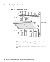
... Q OC-3/STM-POS GIGABIT ROUTE PROCESSOR CSC 10 SFC 12 ALARM Air filter Captive screw Air filter tray ~ INPUT: 200 -240V 10 A 50/60 HZ 2000 W ~ INPUT: 200 -240V 10 A 50/60 HZ 2000 W ~ INPUT: 200 -240V 10 A 50/60 HZ 2000 W ~ INPUT: 200 -240V 10 A 50/60 HZ 2000 W 46034 AC OK AC OK...; If the air filter appears dirty, you must replace it . For instructions on replacing the air filter assembly, see "Cleaning the Air Filter" on page 7. 7-6 Cisco 12012 Gigabit Switch Router Installation and Configuration Guide
... Q OC-3/STM-POS GIGABIT ROUTE PROCESSOR CSC 10 SFC 12 ALARM Air filter Captive screw Air filter tray ~ INPUT: 200 -240V 10 A 50/60 HZ 2000 W ~ INPUT: 200 -240V 10 A 50/60 HZ 2000 W ~ INPUT: 200 -240V 10 A 50/60 HZ 2000 W ~ INPUT: 200 -240V 10 A 50/60 HZ 2000 W 46034 AC OK AC OK...; If the air filter appears dirty, you must replace it . For instructions on replacing the air filter assembly, see "Cleaning the Air Filter" on page 7. 7-6 Cisco 12012 Gigabit Switch Router Installation and Configuration Guide
Installation Guide
Page 251
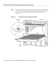
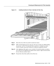
... filter tray against the chassis. Step 9 With one quarter turn to ensure a tight seal between the new air filter tray and the chassis. Maintaining the Cisco 12012 7-11 Step 10 After tightening both captive screws with the 3/16-inch flat-blade screwdriver, give each screw an additional one hand apply pressure to... Filter in the New Air Filter Tray FAIL ENABLED 0 OC-12/STM-4 POS OC-12/STM-4 ATM Q OC-3/STM-POS GIGABIT ROUTE PROCESSOR CSC 10 SFC 12 ALARM 46031 Step 8 Raise the new air filter tray until it touches the chassis.
... filter tray against the chassis. Step 9 With one quarter turn to ensure a tight seal between the new air filter tray and the chassis. Maintaining the Cisco 12012 7-11 Step 10 After tightening both captive screws with the 3/16-inch flat-blade screwdriver, give each screw an additional one hand apply pressure to... Filter in the New Air Filter Tray FAIL ENABLED 0 OC-12/STM-4 POS OC-12/STM-4 ATM Q OC-3/STM-POS GIGABIT ROUTE PROCESSOR CSC 10 SFC 12 ALARM 46031 Step 8 Raise the new air filter tray until it touches the chassis.
Installation Guide
Page 284
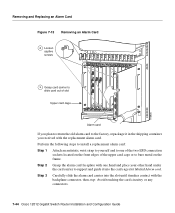
... slide card out of the upper card cage or to bare metal on the frame. Avoid touching the card circuitry or any connectors. 7-44 Cisco 12012 Gigabit Switch Router Installation and Configuration Guide Step 3 Carefully slide the alarm card carrier into the card cage slot labeled Alarm card. Step 2 Grasp the alarm card... of slot Upper card cage ALARM 1 ACO/LT OC-12/STM-4 POS OC-12/STM-4 ATM Q OC-3/STM-POS ALARM 2 FAIL ENABLED 0 H10906 CSC 10 SFC 12 ALARM Alarm card If you received with the backplane connector, then stop.
... slide card out of the upper card cage or to bare metal on the frame. Avoid touching the card circuitry or any connectors. 7-44 Cisco 12012 Gigabit Switch Router Installation and Configuration Guide Step 3 Carefully slide the alarm card carrier into the card cage slot labeled Alarm card. Step 2 Grasp the alarm card... of slot Upper card cage ALARM 1 ACO/LT OC-12/STM-4 POS OC-12/STM-4 ATM Q OC-3/STM-POS ALARM 2 FAIL ENABLED 0 H10906 CSC 10 SFC 12 ALARM Alarm card If you received with the backplane connector, then stop.