

Hardware Installation Guide
Page 3
...-2CS Switch Front Panel 1-5 10/100 Ports (Only the Cisco ME-3400-24TS Switches) 1-6 Dual-Purpose Ports (Only the Cisco ME 3400G-12CS and Cisco ME 3400G-2CS Switches) 1-6 SFP Module Ports 1-7 SFP Modules 1-7 SFP Module Patch Cable 1-8 LEDs 1-8 System LED 1-8 Power Supply LEDs (Only Cisco ME 3400G-12CS Switches) 1-10 Port LEDs 1-10 Dual-Purpose Port LEDs...
...-2CS Switch Front Panel 1-5 10/100 Ports (Only the Cisco ME-3400-24TS Switches) 1-6 Dual-Purpose Ports (Only the Cisco ME 3400G-12CS and Cisco ME 3400G-2CS Switches) 1-6 SFP Module Ports 1-7 SFP Modules 1-7 SFP Module Patch Cable 1-8 LEDs 1-8 System LED 1-8 Power Supply LEDs (Only Cisco ME 3400G-12CS Switches) 1-10 Port LEDs 1-10 Dual-Purpose Port LEDs...
Hardware Installation Guide
Page 4
... Hardware Installation Guide iv OL-7677-04 Contents 2 C H A P T E R Power Supply Features 1-13 Cisco ME AC Switch Power Supply 1-14 Cisco ME DC Switch Power Supply 1-14 Management Options 1-14 Network Configurations 1-14 Switch Installation 2-1 Preparing for Installation 2-1 Warnings 2-1 Cisco ME 3400-24TS Switches 2-4 Cisco ME 3400G-12CS Switches 2-4 Installation Guidelines 2-4 Verifying Switch Operation 2-5 Powering Off the Switch 2-5 Installing the Switch 2-5 Rack-Mounting...
... Hardware Installation Guide iv OL-7677-04 Contents 2 C H A P T E R Power Supply Features 1-13 Cisco ME AC Switch Power Supply 1-14 Cisco ME DC Switch Power Supply 1-14 Management Options 1-14 Network Configurations 1-14 Switch Installation 2-1 Preparing for Installation 2-1 Warnings 2-1 Cisco ME 3400-24TS Switches 2-4 Cisco ME 3400G-12CS Switches 2-4 Installation Guidelines 2-4 Verifying Switch Operation 2-5 Powering Off the Switch 2-5 Installing the Switch 2-5 Rack-Mounting...

Hardware Installation Guide
Page 11
...Panel Description, page 1-12 • Power Supply Features, page 1-13 • Management Options, page 1-14 Setting up your model, the switches support either AC or DC power. This chapter provides a functional overview of the Cisco ME switch. Switch Models The Cisco ME switch can connect other network devices..., such as routers, other network devices. OL-7677-04 Cisco ME 3400 Ethernet Access Switch Hardware ...
...Panel Description, page 1-12 • Power Supply Features, page 1-13 • Management Options, page 1-14 Setting up your model, the switches support either AC or DC power. This chapter provides a functional overview of the Cisco ME switch. Switch Models The Cisco ME switch can connect other network devices..., such as routers, other network devices. OL-7677-04 Cisco ME 3400 Ethernet Access Switch Hardware ...
Hardware Installation Guide
Page 14
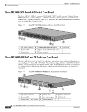
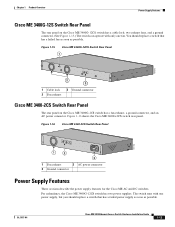
...Cisco ME 3400G-12CS-AC Ethernet Access Switch Front Panel 191302 SYSTEM 1A-01.0R50AA-2,T45IN00GV-60~ HZ 1A-01.0R50AA-2,T45IN00GV-60~ HZ PS 1 PS 2 CONSOLE 1 34 1 2 3 4 5 6 7 8 9 10 11 12 5 Cisco ME 3400 SERIES 13 15 14 16 67 8 1 AC power connectors 4 Console port 7 Ground connectors 2 System LED 5 Dual-purpose ports 8 Cable lock 3 Power supply... 1 and 2 LEDs 6 SFP module ports Cisco ME 3400 Ethernet Access...
...Cisco ME 3400G-12CS-AC Ethernet Access Switch Front Panel 191302 SYSTEM 1A-01.0R50AA-2,T45IN00GV-60~ HZ 1A-01.0R50AA-2,T45IN00GV-60~ HZ PS 1 PS 2 CONSOLE 1 34 1 2 3 4 5 6 7 8 9 10 11 12 5 Cisco ME 3400 SERIES 13 15 14 16 67 8 1 AC power connectors 4 Console port 7 Ground connectors 2 System LED 5 Dual-purpose ports 8 Cable lock 3 Power supply... 1 and 2 LEDs 6 SFP module ports Cisco ME 3400 Ethernet Access...
Hardware Installation Guide
Page 15
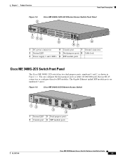
... Figure 1-5 2 Cisco ME 3400G-12CS-DC Ethernet Access Switch Front Panel CINUPR+AURTE-N36TB+-2 -72 V - 1A CINUPR+AURTE-N36TB+-2 -72 V - 1A SYSTEM PS 1 PS 2 CONSOLE 1 34 1 2 3 4 5 6 7 8 9 10 11 12 5 Cisco ME 3400 SERIES 13 15 14 16 67 8 1 DC power connectors 4 Console port 7 Ground connectors 2 System LED 5 Dual-purpose ports 8 Cable lock 3 Power supply 1 and 2 LEDs...
... Figure 1-5 2 Cisco ME 3400G-12CS-DC Ethernet Access Switch Front Panel CINUPR+AURTE-N36TB+-2 -72 V - 1A CINUPR+AURTE-N36TB+-2 -72 V - 1A SYSTEM PS 1 PS 2 CONSOLE 1 34 1 2 3 4 5 6 7 8 9 10 11 12 5 Cisco ME 3400 SERIES 13 15 14 16 67 8 1 DC power connectors 4 Console port 7 Ground connectors 2 System LED 5 Dual-purpose ports 8 Cable lock 3 Power supply 1 and 2 LEDs...

Hardware Installation Guide
Page 18
...LED, page 1-8 • Power Supply LEDs (Only Cisco ME 3400G-12CS Switches), page 1-10 • Port LEDs, page 1-10 • Dual-Purpose Port LEDs, page 1-11 These illustrations show the location of the System LED: • Figure 1-8 on page 1-9, Cisco ME 3400-24TS and Cisco ME 3400-24FS Switches •...; Figure 1-9 on page 1-9, Cisco ME 3400-12CS Switch • Figure 1-10 on page 1-9, Cisco ME 3400G-2CS Switch Cisco ME 3400 Ethernet Access Switch Hardware Installation Guide 1-8 OL-7677...
...LED, page 1-8 • Power Supply LEDs (Only Cisco ME 3400G-12CS Switches), page 1-10 • Port LEDs, page 1-10 • Dual-Purpose Port LEDs, page 1-11 These illustrations show the location of the System LED: • Figure 1-8 on page 1-9, Cisco ME 3400-24TS and Cisco ME 3400-24FS Switches •...; Figure 1-9 on page 1-9, Cisco ME 3400-12CS Switch • Figure 1-10 on page 1-9, Cisco ME 3400G-2CS Switch Cisco ME 3400 Ethernet Access Switch Hardware Installation Guide 1-8 OL-7677...
Hardware Installation Guide
Page 20
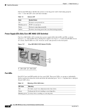
...interpret the port LED colors. The lit LED shows which power supply is sending or receiving data. 1-10 Cisco ME 3400 Ethernet Access Switch Hardware Installation Guide OL-7677-04 Figure 1-11 Cisco ME 3400G-12CS Switch PS LEDs Port LEDs PS1 PS2 SYSTEM 1A-01....Panel Description Chapter 1 Product Overview The System LED shows whether the system is receiving power and is operating normally. Power Supply LEDs (Only Cisco ME 3400G-12CS Switches) The Cisco ME 3400G-12CS switches have power supply LEDs labeled PS1 and PS2, as a group or individually, display information about the...
...interpret the port LED colors. The lit LED shows which power supply is sending or receiving data. 1-10 Cisco ME 3400 Ethernet Access Switch Hardware Installation Guide OL-7677-04 Figure 1-11 Cisco ME 3400G-12CS Switch PS LEDs Port LEDs PS1 PS2 SYSTEM 1A-01....Panel Description Chapter 1 Product Overview The System LED shows whether the system is receiving power and is operating normally. Power Supply LEDs (Only Cisco ME 3400G-12CS Switches) The Cisco ME 3400G-12CS switches have power supply LEDs labeled PS1 and PS2, as a group or individually, display information about the...
Hardware Installation Guide
Page 23
... exhaust 3 AC power connector 2 Ground connector Power Supply Features These sections describe the power supply features for the Cisco ME AC and DC switches. OL-7677-04 Cisco ME 3400 Ethernet Access Switch Hardware Installation Guide 1-13 You should replace a switch that has a failed fan as soon as possible. For redundancy, the Cisco ME 3400G-12CS switch has two power supplies.
... exhaust 3 AC power connector 2 Ground connector Power Supply Features These sections describe the power supply features for the Cisco ME AC and DC switches. OL-7677-04 Cisco ME 3400 Ethernet Access Switch Hardware Installation Guide 1-13 You should replace a switch that has a failed fan as soon as possible. For redundancy, the Cisco ME 3400G-12CS switch has two power supplies.

Hardware Installation Guide
Page 24
...part number 1757035, www.phoenixcontact.com Management Options These management options are interconnected through an internal power supply. See the switch command reference on connecting the Cisco ME DC switches. See the CiscoView documentation for more information. • SNMP network management You... switch supports a comprehensive set configuration parameters and to view switch status and performance information. Cisco ME DC Switch Power Supply The Cisco ME DC switch internal power supplies support input voltages between 100 and 240 VAC. You can be a standalone application or ...
...part number 1757035, www.phoenixcontact.com Management Options These management options are interconnected through an internal power supply. See the switch command reference on connecting the Cisco ME DC switches. See the CiscoView documentation for more information. • SNMP network management You... switch supports a comprehensive set configuration parameters and to view switch status and performance information. Cisco ME DC Switch Power Supply The Cisco ME DC switch internal power supplies support input voltages between 100 and 240 VAC. You can be a standalone application or ...

Hardware Installation Guide
Page 27
...national laws and regulations. Statement 1073 Warning Installation of the equipment must be removed to be allowed to all switches except the Cisco ME 3400G-2CS switch: Warning Only trained and qualified personnel should be handled according to install, replace, or service this ... with the Telcordia GR-1089 Network Equipment Building Systems (NEBS) standard for Installation Warning This unit might have more than one power supply connection. Statement 1045 Warning When installing or replacing the unit, the ground connection must be made first and disconnected last. Install...
...national laws and regulations. Statement 1073 Warning Installation of the equipment must be removed to be allowed to all switches except the Cisco ME 3400G-2CS switch: Warning Only trained and qualified personnel should be handled according to install, replace, or service this ... with the Telcordia GR-1089 Network Equipment Building Systems (NEBS) standard for Installation Warning This unit might have more than one power supply connection. Statement 1045 Warning When installing or replacing the unit, the ground connection must be made first and disconnected last. Install...
Hardware Installation Guide
Page 38
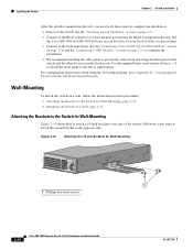
...using the CLI setup program, go to the left or right bracket. Use the supplied black screw shown in Figure 2-8 to attach the cable guide to Appendix D, ... Figure 2-10 Attaching the 19-inch Brackets for instructions. • Connect to complete the installation: • Power on the switch. Wall-Mounting To install the switch on a wall, follow the instructions in these tasks to...the rack. See the Cisco ME 3400 and ME 2400 Ethernet Access Switches Getting Started Guide for Wall-Mounting 132690 Cisco ME 2400 SERIES 1 2 1 1 Phillips flat-head screws 2-14 Cisco ME 3400 Ethernet Access ...
...using the CLI setup program, go to the left or right bracket. Use the supplied black screw shown in Figure 2-8 to attach the cable guide to Appendix D, ... Figure 2-10 Attaching the 19-inch Brackets for instructions. • Connect to complete the installation: • Power on the switch. Wall-Mounting To install the switch on a wall, follow the instructions in these tasks to...the rack. See the Cisco ME 3400 and ME 2400 Ethernet Access Switches Getting Started Guide for Wall-Mounting 132690 Cisco ME 2400 SERIES 1 2 1 1 Phillips flat-head screws 2-14 Cisco ME 3400 Ethernet Access ...
Hardware Installation Guide
Page 39
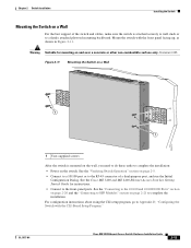
... make sure the switch is mounted on the wall, you need to do these tasks to complete the installation: • Power on the switch. OL-7677-04 Cisco ME 3400 Ethernet Access Switch Hardware Installation Guide 2-15 Statement 345 Figure 2-11 Mounting the Switch on a Wall Catalyst 3750 ...SERIES 2X 14X 13X SYST 2X 132673 1 1 1 User-supplied screws After the switch is attached securely to wall studs or to Appendix D, ...
... make sure the switch is mounted on the wall, you need to do these tasks to complete the installation: • Power on the switch. OL-7677-04 Cisco ME 3400 Ethernet Access Switch Hardware Installation Guide 2-15 Statement 345 Figure 2-11 Mounting the Switch on a Wall Catalyst 3750 ...SERIES 2X 14X 13X SYST 2X 132673 1 1 1 User-supplied screws After the switch is attached securely to wall studs or to Appendix D, ...
Hardware Installation Guide
Page 72
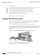
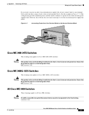
... the circuit boards are not receiving power from an internal power supply, the software sends a message like this alert if power fails on the ME 3400G-12CS-DC switch with two power feeds, we recommend that an internal power supply is not providing power. Repeat these steps: Step 1... 1 PS 2 CONSOLE 1 Primary power feed 2 Secondary (redundant) power feed 191863 Cisco ME 3400 Ethernet Access Switch Hardware Installation Guide C-6 OL-7677-04 Wiring the DC-Input Power Source Appendix C Connecting to the console: 00:06:54: %POWER_SUPPLIES-3-PWR_FAIL: Power supply 2 is not functioning 00:06:...
... the circuit boards are not receiving power from an internal power supply, the software sends a message like this alert if power fails on the ME 3400G-12CS-DC switch with two power feeds, we recommend that an internal power supply is not providing power. Repeat these steps: Step 1... 1 PS 2 CONSOLE 1 Primary power feed 2 Secondary (redundant) power feed 191863 Cisco ME 3400 Ethernet Access Switch Hardware Installation Guide C-6 OL-7677-04 Wiring the DC-Input Power Source Appendix C Connecting to the console: 00:06:54: %POWER_SUPPLIES-3-PWR_FAIL: Power supply 2 is not functioning 00:06:...
Hardware Installation Guide
Page 73
...that the protective device is rated not greater than : 5 A Statement 1005 Cisco ME 3400G-12CS Switches This warning only applies to Cisco ME 3400G-12CS switches: Warning This product relies on the building's installation for short-circuit (...overcurrent) protection. Figure C-7 Connecting Feeds from there connect feeds to the second terminal block. (See the example in the fixed wiring. However, the software does not send a message to you want to receive an alert if an external power supply...
...that the protective device is rated not greater than : 5 A Statement 1005 Cisco ME 3400G-12CS Switches This warning only applies to Cisco ME 3400G-12CS switches: Warning This product relies on the building's installation for short-circuit (...overcurrent) protection. Figure C-7 Connecting Feeds from there connect feeds to the second terminal block. (See the example in the fixed wiring. However, the software does not send a message to you want to receive an alert if an external power supply...
Hardware Installation Guide
Page 74
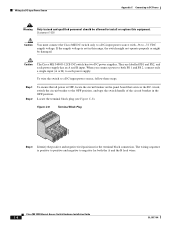
...PS2, and each power supply. Wiring the DC-Input Power Source Appendix C Connecting to DC Power Warning Only trained and qualified personnel should be damaged. Locate the terminal block plug (see Figure C-8). Caution The Cisco ME 3400G-12CS-DC switch has two DC power supplies. When you connect power to both the A... and the B feed wires. Statement 1030 Caution You must connect the Cisco ME DC switch only to a DC-input power source with -36 to install or...
...PS2, and each power supply. Wiring the DC-Input Power Source Appendix C Connecting to DC Power Warning Only trained and qualified personnel should be damaged. Locate the terminal block plug (see Figure C-8). Caution The Cisco ME 3400G-12CS-DC switch has two DC power supplies. When you connect power to both the A... and the B feed wires. Statement 1030 Caution You must connect the Cisco ME DC switch only to a DC-input power source with -36 to install or...
Hardware Installation Guide
Page 76
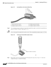
...Input Power Source Figure C-11 Inserting Wires in the Terminal Block Plug 1 2 3 4 Appendix C Connecting to DC Power 132849 1 Return (positive) Feed A 2 Supply (negative) Feed A 3 Return (positive) Feed B 4 Supply (...negative) Feed B Step 6 Use a ratcheting torque screwdriver to torque the terminal block captive screw (above the installed wire lead) to 4.5 lbf-in. (72 ozf-in.) 60533 Step 7 Repeat Steps 4 and 5 for the remaining three DC-input power source wires. C-10 Cisco...
...Input Power Source Figure C-11 Inserting Wires in the Terminal Block Plug 1 2 3 4 Appendix C Connecting to DC Power 132849 1 Return (positive) Feed A 2 Supply (negative) Feed A 3 Return (positive) Feed B 4 Supply (...negative) Feed B Step 6 Use a ratcheting torque screwdriver to torque the terminal block captive screw (above the installed wire lead) to 4.5 lbf-in. (72 ozf-in.) 60533 Step 7 Repeat Steps 4 and 5 for the remaining three DC-input power source wires. C-10 Cisco...

Hardware Installation Guide
Page 82
... using Telnet. After you complete the setup program, the switch can run the default configuration that the second power supply is not operating. Enter your selection [2]:2 Make your selection, and press Return. To use it in NVRAM by using a Cisco ME 3400-12CS switch with the CLI-Based Setup Program ! interface FastEthernet1/0/2 interface FastEthernet1/0/3 ! ...
... using Telnet. After you complete the setup program, the switch can run the default configuration that the second power supply is not operating. Enter your selection [2]:2 Make your selection, and press Return. To use it in NVRAM by using a Cisco ME 3400-12CS switch with the CLI-Based Setup Program ! interface FastEthernet1/0/2 interface FastEthernet1/0/3 ! ...
Hardware Installation Guide
Page 85
...-inch racks 2-8 to 2-9 attaching to 23-inch racks 2-10 attaching to 24-inch racks 2-11 attaching to ETSI racks 2-12 multiple power supply warning 2-3 N NEBS compliance 2-3 network configuration examples 1-1 Network Equipment Building Systems See NEBS compliance noise, electrical 2-4 O overcurrent protection warning 2-4, C-7 overheating warning 2-3 Cisco ME 3400 Ethernet Access Switch Hardware Installation Guide IN-3
...-inch racks 2-8 to 2-9 attaching to 23-inch racks 2-10 attaching to 24-inch racks 2-11 attaching to ETSI racks 2-12 multiple power supply warning 2-3 N NEBS compliance 2-3 network configuration examples 1-1 Network Equipment Building Systems See NEBS compliance noise, electrical 2-4 O overcurrent protection warning 2-4, C-7 overheating warning 2-3 Cisco ME 3400 Ethernet Access Switch Hardware Installation Guide IN-3
Hardware Installation Guide
Page 86
...dual-purpose ports 1-4 to 1-5 numbering of SFP module slots 1-3 to 1-5 SFP module 1-7 POST LEDs 3-1 running at power on 3-1 power connecting to AC 2-5, D-2 connecting to DC 2-5, D-2 power on 2-5, D-2 power source warning 2-2 power supply, AC power outlet 1-14 procedures connection 2-20 to 2-23 installation 2-5 to 2-16 product disposal warning 2-3 PS1 and PS2 LEDs 1-10...-BX 1-7 100BASE-FX 1-7 100BASE-LX 1-7 bale-clasp latch removal 2-18 cables B-4 connecting to 2-21 to 2-23 connectors B-3 CWDM 1-7 described 1-7 IN-4 Cisco ME 3400 Ethernet Access Switch Hardware Installation Guide OL-7677-04
...dual-purpose ports 1-4 to 1-5 numbering of SFP module slots 1-3 to 1-5 SFP module 1-7 POST LEDs 3-1 running at power on 3-1 power connecting to AC 2-5, D-2 connecting to DC 2-5, D-2 power on 2-5, D-2 power source warning 2-2 power supply, AC power outlet 1-14 procedures connection 2-20 to 2-23 installation 2-5 to 2-16 product disposal warning 2-3 PS1 and PS2 LEDs 1-10...-BX 1-7 100BASE-FX 1-7 100BASE-LX 1-7 bale-clasp latch removal 2-18 cables B-4 connecting to 2-21 to 2-23 connectors B-3 CWDM 1-7 described 1-7 IN-4 Cisco ME 3400 Ethernet Access Switch Hardware Installation Guide OL-7677-04

Hardware Installation Guide
Page 87
...twisted-pair 1000BASE-T ports B-6 two twisted-pair 10/100 ports B-5 SunNet Manager 1-14 switch models illustrated 1-3 switch powering on 2-5, D-2 system LED 1-10 T table-mounting 2-16 technical specifications A-1 to A-3 telco racks 2-6 Telnet,... activity 2-2 multiple power supply 2-3 no user-serviceable parts 2-3 overcurrent protection 2-4 overheating 2-3 plug-socket combination 2-2 power source 2-2 rack-mounting 2-2 restricted access area 2-2, C-1 shield Ethernet cables 2-2 short-circuit (overcurrent) protection 2-4, C-7 short-circuit protection 2-3 to 2-4 Cisco ME 3400 Ethernet Access...
...twisted-pair 1000BASE-T ports B-6 two twisted-pair 10/100 ports B-5 SunNet Manager 1-14 switch models illustrated 1-3 switch powering on 2-5, D-2 system LED 1-10 T table-mounting 2-16 technical specifications A-1 to A-3 telco racks 2-6 Telnet,... activity 2-2 multiple power supply 2-3 no user-serviceable parts 2-3 overcurrent protection 2-4 overheating 2-3 plug-socket combination 2-2 power source 2-2 rack-mounting 2-2 restricted access area 2-2, C-1 shield Ethernet cables 2-2 short-circuit (overcurrent) protection 2-4, C-7 short-circuit protection 2-3 to 2-4 Cisco ME 3400 Ethernet Access...


