Quick Start Guide
Page 2
Part of the market-leading Cisco PIX 500 series, the Cisco PIX 515E security appliance provides a wide range of all sizes. About the Cisco PIX 515E Security Appliance 132235 POWER ACT NETWORK PIX Firewall SERIES The Cisco PIX 515E security appliance delivers enterprise-class security for use in a VPN or DMZ deployment. For more information, refer to -deploy, high-performance solution. Ranging from compact...
Part of the market-leading Cisco PIX 500 series, the Cisco PIX 515E security appliance provides a wide range of all sizes. About the Cisco PIX 515E Security Appliance 132235 POWER ACT NETWORK PIX Firewall SERIES The Cisco PIX 515E security appliance delivers enterprise-class security for use in a VPN or DMZ deployment. For more information, refer to -deploy, high-performance solution. Ranging from compact...
Quick Start Guide
Page 3
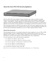
... Verify the contents of the packing box to ensure that you have received all items necessary to install and configure your PIX 515E security appliance. PC terminal adapter (74-0495-01) PIX-515E DO NOT INSTALL INTERFACE CARDS WITH POWER APPLIED 100 Mbps Link FDX 100 Mbps Link FDX 10/100 ETHERNET 1 10/...100 ETHERNET 0 PIX 515E FAILOVER CONSOLE Blue console cable (72-1259-01) Yellow Ethernet cable (72-1482-01) Failover serial cable (74-1213-01) Power cable Rubber feet ...
... Verify the contents of the packing box to ensure that you have received all items necessary to install and configure your PIX 515E security appliance. PC terminal adapter (74-0495-01) PIX-515E DO NOT INSTALL INTERFACE CARDS WITH POWER APPLIED 100 Mbps Link FDX 100 Mbps Link FDX 10/100 ETHERNET 1 10/...100 ETHERNET 0 PIX 515E FAILOVER CONSOLE Blue console cable (72-1259-01) Yellow Ethernet cable (72-1482-01) Failover serial cable (74-1213-01) Power cable Rubber feet ...
Quick Start Guide
Page 4
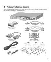
.... Attach the brackets to the equipment rack. Attach the chassis to the chassis with the supplied screws. Connect one of the PIX 515E security appliance and the other provided yellow Ethernet cable (72-1482-01) to connect the inside 10/100 Ethernet interface, Ethernet ...Step 3 Step 4 Step 5 Mount the chassis in Figure 1. b. Use the other end to a power outlet. 2 Installing the PIX 515E Security Appliance This section describes how to install your PIX 515E security appliance into your own network, which might resemble the model in a rack by performing the following steps: a.
.... Attach the brackets to the equipment rack. Attach the chassis to the chassis with the supplied screws. Connect one of the PIX 515E security appliance and the other provided yellow Ethernet cable (72-1482-01) to connect the inside 10/100 Ethernet interface, Ethernet ...Step 3 Step 4 Step 5 Mount the chassis in Figure 1. b. Use the other end to a power outlet. 2 Installing the PIX 515E Security Appliance This section describes how to install your PIX 515E security appliance into your own network, which might resemble the model in a rack by performing the following steps: a.
Quick Start Guide
Page 8
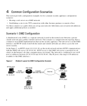
... most DMZ implementations that use an IP pool of IP addresses available to the DMZ interface.) Figure 2 Network Layout for DMZ Configuration Scenario HTTP client PIX 515E Inside 10.10.10.0 Outside 209.165.156.10 10.10.10.10 DMZ 30.30.30.0 Internet HTTP client HTTP client 97999 Web server...
... most DMZ implementations that use an IP pool of IP addresses available to the DMZ interface.) Figure 2 Network Layout for DMZ Configuration Scenario HTTP client PIX 515E Inside 10.10.10.0 Outside 209.165.156.10 10.10.10.10 DMZ 30.30.30.0 Internet HTTP client HTTP client 97999 Web server...
Quick Start Guide
Page 29
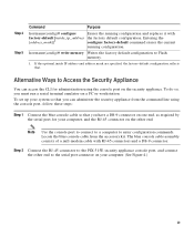
... for administration using the console port, follow these steps: Step 1 Connect the blue console cable so that . Step 2 Connect the RJ-45 connector to the PIX 515E security appliance console port, and connect the other end. hostname(config)# write memory Writes the factory default configuration to enter configuration commands. Note Use the...
... for administration using the console port, follow these steps: Step 1 Connect the blue console cable so that . Step 2 Connect the RJ-45 connector to the PIX 515E security appliance console port, and connect the other end. hostname(config)# write memory Writes the factory default configuration to enter configuration commands. Note Use the...
Quick Start Guide
Page 30
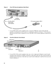
... so that the top circuit board is Ethernet 2 and the bottom circuit board is required to access the PIX 515E security appliance unrestricted license. PIX-515 99547 Figure 4 Cisco PIX Security Appliance Back Panel 100 Mbps Link FDX 10/100 ETHERNET 0/0 FAILOVER CONSOLE Console port (RJ-45) RJ...-45 to DB-9 serial cable (null-modem) PC terminal adapter DB-9 • If your PIX 515E security appliance has one ...
... so that the top circuit board is Ethernet 2 and the bottom circuit board is required to access the PIX 515E security appliance unrestricted license. PIX-515 99547 Figure 4 Cisco PIX Security Appliance Back Panel 100 Mbps Link FDX 10/100 ETHERNET 0/0 FAILOVER CONSOLE Console port (RJ-45) RJ...-45 to DB-9 serial cable (null-modem) PC terminal adapter DB-9 • If your PIX 515E security appliance has one ...
Quick Start Guide
Page 31
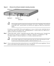
... PIX-515 99545 Ethernet 3 DO NOT INSTALL INTERFACE CARDS WITH POWER APPLIED 100 Mbps Link FDX 100 Mbps Link FDX 10/100 ETHERNET 0/0 10/100 ETHERNET 0/0 FAILOVER CONSOLE Ethernet 1 Ethernet 0 Note If you have a second PIX 515E security appliance to the "Installing a Circuit Board in the PIX 515E" section in the Cisco PIX Security... board because the maximum number of allowed interfaces is six. Note Do not add a single-port circuit board in the Cisco PIX Security Appliance Hardware Installation Guide. The maximum number of allowed interfaces is six with an unrestricted license.
... PIX-515 99545 Ethernet 3 DO NOT INSTALL INTERFACE CARDS WITH POWER APPLIED 100 Mbps Link FDX 100 Mbps Link FDX 10/100 ETHERNET 0/0 10/100 ETHERNET 0/0 FAILOVER CONSOLE Ethernet 1 Ethernet 0 Note If you have a second PIX 515E security appliance to the "Installing a Circuit Board in the PIX 515E" section in the Cisco PIX Security... board because the maximum number of allowed interfaces is six. Note Do not add a single-port circuit board in the Cisco PIX Security Appliance Hardware Installation Guide. The maximum number of allowed interfaces is six with an unrestricted license.
Quick Start Guide
Page 32
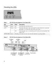
... when the unit has power. If failover is not enabled, this light is the active failover unit. On On when the unit is off. Figure 7 PIX 515E Security Appliance Front Panel LEDs 100 Mbps LED ACT LED DO NOT INSTALL INTERFACE CARDS WITH POWER APPLIED 100 Mbps LED LINK ACT LED LED... USB LINK LED PIX-515 97784 100 Mbps ACT LINK 100 Mbps ACT LINK 10/100 ETHERNET 1 10/100 ETHERNET 0 FAILOVER USB CONSOLE 10/100BaseTX 10/100BaseTX Console Power switch...
... when the unit has power. If failover is not enabled, this light is the active failover unit. On On when the unit is off. Figure 7 PIX 515E Security Appliance Front Panel LEDs 100 Mbps LED ACT LED DO NOT INSTALL INTERFACE CARDS WITH POWER APPLIED 100 Mbps LED LINK ACT LED LED... USB LINK LED PIX-515 97784 100 Mbps ACT LINK 100 Mbps ACT LINK 10/100 ETHERNET 1 10/100 ETHERNET 0 FAILOVER USB CONSOLE 10/100BaseTX 10/100BaseTX Console Power switch...

