Quick Start Guide
Page 5
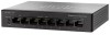
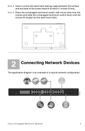
... switch down until the screws fit snugly into each hole, leaving a gap between the surface and the base of the screw head of a typical network configuration. SYSTEM Link/Act 1 2 34 56 7 8 9 10 11 12 / miniGBIC1 Gigabit Link/Act 13 14 15 16 17 18 19 20 21 ...8 17 18 19 20 9 10 11 12 21 22 23 24 (Shared with 12) (Shared with 24) miniGBIC1 miniGBIC2 Cisco Small Business SR2024 24-P or t 10/ 100/ 1000 Swit ch 193803 Cisco Unmanaged Rackmount Switches 4 STEP 3 Insert a screw into the wall-mount slots. 276583 2 Connecting Network Devices The application diagram ...
... switch down until the screws fit snugly into each hole, leaving a gap between the surface and the base of the screw head of a typical network configuration. SYSTEM Link/Act 1 2 34 56 7 8 9 10 11 12 / miniGBIC1 Gigabit Link/Act 13 14 15 16 17 18 19 20 21 ...8 17 18 19 20 9 10 11 12 21 22 23 24 (Shared with 12) (Shared with 24) miniGBIC1 miniGBIC2 Cisco Small Business SR2024 24-P or t 10/ 100/ 1000 Swit ch 193803 Cisco Unmanaged Rackmount Switches 4 STEP 3 Insert a screw into the wall-mount slots. 276583 2 Connecting Network Devices The application diagram ...
Quick Start Guide
Page 6
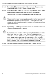
Otherwise, flow control might not be configurable. NOTE To prioritize voice or video traffic by using the QoS feature on the port. The LED of the...want to connect to the switch, blocking the high-priority QoS packets queued on the switch, set flow control to off in the configurations of the port lights if the device connected is normal and expected behavior. STEP 2 Connect the other network device. STEP 4 Connect... switch. This is active. STEP 3 Repeat Step 1 and Step 2 for full network operation to the switch and a power source. 5 Cisco Unmanaged Rackmount Switches
Otherwise, flow control might not be configurable. NOTE To prioritize voice or video traffic by using the QoS feature on the port. The LED of the...want to connect to the switch, blocking the high-priority QoS packets queued on the switch, set flow control to off in the configurations of the port lights if the device connected is normal and expected behavior. STEP 2 Connect the other network device. STEP 4 Connect... switch. This is active. STEP 3 Repeat Step 1 and Step 2 for full network operation to the switch and a power source. 5 Cisco Unmanaged Rackmount Switches


