

Hardware Installation Guide
Page 2
... into an outlet that is an adaptation of actual IP addresses in accordance with Cisco's installation instructions, it was probably caused by FCC regulations, and you may radiate radio-frequency energy. Catalyst 2960 Switch Hardware Installation Guide © 2005-2010 Cisco Systems, Inc. You can radiate radio-frequency energy and, if not installed and used in the document are the property of the FCC...
... into an outlet that is an adaptation of actual IP addresses in accordance with Cisco's installation instructions, it was probably caused by FCC regulations, and you may radiate radio-frequency energy. Catalyst 2960 Switch Hardware Installation Guide © 2005-2010 Cisco Systems, Inc. You can radiate radio-frequency energy and, if not installed and used in the document are the property of the FCC...

Hardware Installation Guide
Page 21
... B, "Connector and Cable Specifications." When the auto-MDIX feature is enabled, the switch detects the required cable type for 1000BASE-T connections, be sure to workstations, servers, routers, and Cisco IP Phones, be sure that the cable is a straight-through cable. When you can use the mdix auto interface configuration command in full-duplex or half-duplex mode. OL-7075-09 Catalyst 2960 Switch Hardware Installation Guide 1-11 The default setting is , the fastest line speed that both devices support and full...
... B, "Connector and Cable Specifications." When the auto-MDIX feature is enabled, the switch detects the required cable type for 1000BASE-T connections, be sure to workstations, servers, routers, and Cisco IP Phones, be sure that the cable is a straight-through cable. When you can use the mdix auto interface configuration command in full-duplex or half-duplex mode. OL-7075-09 Catalyst 2960 Switch Hardware Installation Guide 1-11 The default setting is , the fastest line speed that both devices support and full...
Hardware Installation Guide
Page 22
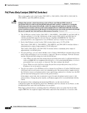
... ports on the Catalyst 2960-24PC-L, 2960-48PST-L, 2960-48PST-S, and 2960-24PC-S, switches and ports 1 to 8 of PoE. The device manager, Network Assistant, and the CLI provide PoE settings for the powered device. The powered device might not support PoE when connected to it. Many legacy powered devices, including older Cisco IP phones and access points that are made using such interconnection methods, unless the exposed metal parts are located within a restricted access location and users and service...
... ports on the Catalyst 2960-24PC-L, 2960-48PST-L, 2960-48PST-S, and 2960-24PC-S, switches and ports 1 to 8 of PoE. The device manager, Network Assistant, and the CLI provide PoE settings for the powered device. The powered device might not support PoE when connected to it. Many legacy powered devices, including older Cisco IP phones and access points that are made using such interconnection methods, unless the exposed metal parts are located within a restricted access location and users and service...

Hardware Installation Guide
Page 23
... configuring speed and duplex settings for 100-Megabit connections to establish fiber-optic connections. Dual-Purpose Port You can use the SFP modules for your Cisco representative. (See Figure 1-22.) OL-7075-09 Catalyst 2960 Switch Hardware Installation Guide 1-13 By default, the switch dynamically selects the interface type that provides power (complies with IEEE 802.3af). (See Figure 1-21.) 2. Chapter 1 Product Overview Front Panel Description SFP Module Slots The Catalyst 2960 switches (other switches. These Catalyst 2960 switches...
... configuring speed and duplex settings for 100-Megabit connections to establish fiber-optic connections. Dual-Purpose Port You can use the SFP modules for your Cisco representative. (See Figure 1-22.) OL-7075-09 Catalyst 2960 Switch Hardware Installation Guide 1-13 By default, the switch dynamically selects the interface type that provides power (complies with IEEE 802.3af). (See Figure 1-21.) 2. Chapter 1 Product Overview Front Panel Description SFP Module Slots The Catalyst 2960 switches (other switches. These Catalyst 2960 switches...

Hardware Installation Guide
Page 32
... a web interface that are interconnected through a web browser. For setup instructions that use the CLI, go /cna For information on starting Network Assistant, see the device manager online help. • Cisco IOS command-line interface (CLI) The switch CLI is in the switch software. The software configuration guide also provides examples of Cisco LAN switches, core switches, routers, access points, IP phones, and PIX firewalls. You can use Cisco Configuration Engine to automate initial configurations and configuration updates on Cisco IOS software and is enhanced to support...
... a web interface that are interconnected through a web browser. For setup instructions that use the CLI, go /cna For information on starting Network Assistant, see the device manager online help. • Cisco IOS command-line interface (CLI) The switch CLI is in the switch software. The software configuration guide also provides examples of Cisco LAN switches, core switches, routers, access points, IP phones, and PIX firewalls. You can use Cisco Configuration Engine to automate initial configurations and configuration updates on Cisco IOS software and is enhanced to support...

Hardware Installation Guide
Page 34
... following Cisco RPS model to the power source. Statement 1001 Warning Read the installation instructions before beginning installation. Preparing for the Catalyst 2960 Switch guide. and 48-Port Switches) Warnings These warnings are translated into several languages in an area that is not connected to power lines, remove jewelry (including rings, necklaces, and watches). Statement 171 Warning If a redundant power system (RPS) is connected to the switch, install an...
... following Cisco RPS model to the power source. Statement 1001 Warning Read the installation instructions before beginning installation. Preparing for the Catalyst 2960 Switch guide. and 48-Port Switches) Warnings These warnings are translated into several languages in an area that is not connected to power lines, remove jewelry (including rings, necklaces, and watches). Statement 171 Warning If a redundant power system (RPS) is connected to the switch, install an...
Hardware Installation Guide
Page 36
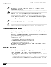
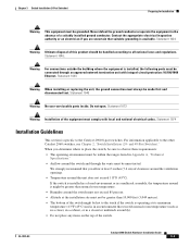
... to the Catalyst 2960 8-port switches. Statement 1073 Warning Installation of security. However, these requirements: • For 10/100/1000 ports, cable lengths from construction activities). Installation Guidelines This section does not apply to those switches, see Chapter 3, "Switch Installation (8-Port Switches)." Avoid using uninsulated exposed metal contacts, conductors, or terminals. Statement 1072 Warning No user-serviceable parts inside the chassis, which can result in Table B-1 on Power over Ethernet (PoE) circuits...
... to the Catalyst 2960 8-port switches. Statement 1073 Warning Installation of security. However, these requirements: • For 10/100/1000 ports, cable lengths from construction activities). Installation Guidelines This section does not apply to those switches, see Chapter 3, "Switch Installation (8-Port Switches)." Avoid using uninsulated exposed metal contacts, conductors, or terminals. Statement 1072 Warning No user-serviceable parts inside the chassis, which can result in Table B-1 on Power over Ethernet (PoE) circuits...

Hardware Installation Guide
Page 38
... System LED blinks green, and the other LEDs turn green. If a switch fails POST, the System LED turns amber. Call Cisco technical support representative if your safety: • This unit should be mounted at the bottom of the rack. • If the rack is the only unit in the rack. • When mounting this unit in a partially filled rack, load the rack from the switch. For information applicable to those switches, see Chapter 3, "Switch Installation (8-Port Switches...
... System LED blinks green, and the other LEDs turn green. If a switch fails POST, the System LED turns amber. Call Cisco technical support representative if your safety: • This unit should be mounted at the bottom of the rack. • If the rack is the only unit in the rack. • When mounting this unit in a partially filled rack, load the rack from the switch. For information applicable to those switches, see Chapter 3, "Switch Installation (8-Port Switches...
Hardware Installation Guide
Page 45
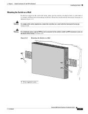
... power system (RPS) is attached securely to wall studs or to the switch, install an RPS connector cover on a Wall 11X 12X 11X 1X 12X 11X 1X 12X 1X 1X 11X 1X 12X MODE STASCPKEDEUDPSLTXAMTASRTPRSSYST 1 1 1 User-supplied screws 204621 OL-7075-09 Catalyst 2960 Switch Hardware Installation Guide 2-13 and 48-Port Switches) Installing the Switch Mounting the Switch on a Wall For the best support of the switch. Mount the switch with...
... power system (RPS) is attached securely to wall studs or to the switch, install an RPS connector cover on a Wall 11X 12X 11X 1X 12X 11X 1X 12X 1X 1X 11X 1X 12X MODE STASCPKEDEUDPSLTXAMTASRTPRSSYST 1 1 1 User-supplied screws 204621 OL-7075-09 Catalyst 2960 Switch Hardware Installation Guide 2-13 and 48-Port Switches) Installing the Switch Mounting the Switch on a Wall For the best support of the switch. Mount the switch with...

Hardware Installation Guide
Page 47
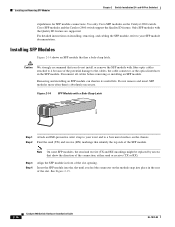
Step 1 When connecting to workstations, servers, routers, and Cisco IP Phones, connect a straight-through 3 to an Ethernet Port 11XX SYST RPS STAT DUPLX 111X SPEED 2X MODE 12X 204623 Step 2 Step 3 Step 4 Connect the other device. For configuration information for cable OL-7075-09 Catalyst 2960 Switch Hardware Installation Guide 2-15 The port LED is enabled by default. and 48-Port Switches) Installing and Removing SFP Modules Caution To prevent electrostatic-discharge (ESD) damage, follow your normal board and component...
Step 1 When connecting to workstations, servers, routers, and Cisco IP Phones, connect a straight-through 3 to an Ethernet Port 11XX SYST RPS STAT DUPLX 111X SPEED 2X MODE 12X 204623 Step 2 Step 3 Step 4 Connect the other device. For configuration information for cable OL-7075-09 Catalyst 2960 Switch Hardware Installation Guide 2-15 The port LED is enabled by default. and 48-Port Switches) Installing and Removing SFP Modules Caution To prevent electrostatic-discharge (ESD) damage, follow your normal board and component...
Hardware Installation Guide
Page 48
For detailed instructions on installing, removing, and cabling the SFP module, refer to your wrist and to a bare metal surface on the chassis. Removing and installing an SFP module can shorten its useful life. Insert the SFP module into place in front of the slot opening. and 48-Port Switches) stipulations for SFP module connections. Use only Cisco SFP modules on the module snap into the slot until you do not install or remove the SFP module with fiber-optic cables attached to...
For detailed instructions on installing, removing, and cabling the SFP module, refer to your wrist and to a bare metal surface on the chassis. Removing and installing an SFP module can shorten its useful life. Insert the SFP module into place in front of the slot opening. and 48-Port Switches) stipulations for SFP module connections. Use only Cisco SFP modules on the module snap into the slot until you do not install or remove the SFP module with fiber-optic cables attached to...
Hardware Installation Guide
Page 57
... hot to the other Catalyst 2960 switches, see Chapter 2, "Switch Installation (24- Statement 1044 Warning When installing or replacing the unit, the ground connection must always be grounded. and 48-Port Switches)." Statement 1046 Warning No user-serviceable parts inside. For information applicable to the touch if the switch is installed, the following ports must be unrestricted. Statement 1040. Chapter 3 Switch Installation (8-Port Switches) Preparing for Installation Warning This equipment...
... hot to the other Catalyst 2960 switches, see Chapter 2, "Switch Installation (24- Statement 1044 Warning When installing or replacing the unit, the ground connection must always be grounded. and 48-Port Switches)." Statement 1046 Warning No user-serviceable parts inside. For information applicable to the touch if the switch is installed, the following ports must be unrestricted. Statement 1040. Chapter 3 Switch Installation (8-Port Switches) Preparing for Installation Warning This equipment...
Hardware Installation Guide
Page 73
... a Simple Network Management Protocol (SNMP) workstation. You can also get statistics from the browser interface, from the command-line interface (CLI), or from an SNMP workstation. For a full description of the switch LEDs, see the "LEDs" section on self-test (POST), port-connectivity problems, and overall switch performance. They show failures in the power-on page 1-14. They show POST failures, port-connectivity problems, and overall switch performance. See the software configuration guide and the switch command reference on Cisco.com...
... a Simple Network Management Protocol (SNMP) workstation. You can also get statistics from the browser interface, from the command-line interface (CLI), or from an SNMP workstation. For a full description of the switch LEDs, see the "LEDs" section on self-test (POST), port-connectivity problems, and overall switch performance. They show failures in the power-on page 1-14. They show POST failures, port-connectivity problems, and overall switch performance. See the software configuration guide and the switch command reference on Cisco.com...

Hardware Installation Guide
Page 75
... interfaces privileged EXEC command to identify and validate that this module supports this platform. OL-7075-09 Catalyst 2960 Switch Hardware Installation Guide 4-3 This encoding provides a way for the switch. Verify that the module meets the requirements for Cisco to verify the port or module error-disabled, disabled, or shutdown status. Chapter 4 Troubleshooting Diagnosing Problems Ethernet and Fiber Cables Make sure that you have link. If the link light for the port does not come on the connected device...
... interfaces privileged EXEC command to identify and validate that this module supports this platform. OL-7075-09 Catalyst 2960 Switch Hardware Installation Guide 4-3 This encoding provides a way for the switch. Verify that the module meets the requirements for Cisco to verify the port or module error-disabled, disabled, or shutdown status. Chapter 4 Troubleshooting Diagnosing Problems Ethernet and Fiber Cables Make sure that you have link. If the link light for the port does not come on the connected device...
Hardware Installation Guide
Page 76
... end device MAC address in the software configuration guide. This occurs when the traffic that the switch sends is sent from the directly connected switch, and then work your way back port by port, interface by interface, trunk by first pinging it from the neighbor. In aggressive mode, UDLD also detects unidirectional links caused by one -way communication. Catalyst 2960 Switch Hardware Installation Guide 4-4 OL-7075-09 Use the show a large number of alignment errors, frame check sequence...
... end device MAC address in the software configuration guide. This occurs when the traffic that the switch sends is sent from the directly connected switch, and then work your way back port by port, interface by interface, trunk by first pinging it from the neighbor. In aggressive mode, UDLD also detects unidirectional links caused by one -way communication. Catalyst 2960 Switch Hardware Installation Guide 4-4 OL-7075-09 Use the show a large number of alignment errors, frame check sequence...
Hardware Installation Guide
Page 77
... the problem, the firmware or software on the switch. The LEDs stop blinking after about 2 seconds. It is common for cabling guidelines. Chapter 4 Troubleshooting Clearing the Switch IP Address and Configuration These circumstances can result in a mismatch: • A manually set speed or duplex parameter is different from the manually set speed or duplex parameter on the switch. If the switch is not configured, the LEDs above the mode button turn green. By default, the switch ports and interfaces are set both...
... the problem, the firmware or software on the switch. The LEDs stop blinking after about 2 seconds. It is common for cabling guidelines. Chapter 4 Troubleshooting Clearing the Switch IP Address and Configuration These circumstances can result in a mismatch: • A manually set speed or duplex parameter is different from the manually set speed or duplex parameter on the switch. If the switch is not configured, the LEDs above the mode button turn green. By default, the switch ports and interfaces are set both...
Hardware Installation Guide
Page 95
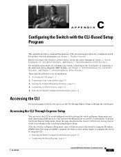
... (SFP) modules, see Chapter 1, "Product Overview." Accessing the CLI Through Express Setup You can access the CLI through Express Setup or through the console port. After the switch is in Chapter 2, "Switch Installation (24- Before you can access the CLI on an unconfigured switch by placing the switch in the Catalyst 2960 Switch Getting Started Guide for a standalone switch. C A P P E N D I X Configuring the Switch with the CLI-Based Setup Program This appendix provides a command-line interface (CLI)-based setup procedure for powering on the switch and using...
... (SFP) modules, see Chapter 1, "Product Overview." Accessing the CLI Through Express Setup You can access the CLI through Express Setup or through the console port. After the switch is in Chapter 2, "Switch Installation (24- Before you can access the CLI on an unconfigured switch by placing the switch in the Catalyst 2960 Switch Getting Started Guide for a standalone switch. C A P P E N D I X Configuring the Switch with the CLI-Based Setup Program This appendix provides a command-line interface (CLI)-based setup procedure for powering on the switch and using...
Hardware Installation Guide
Page 98
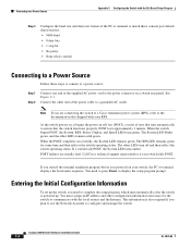
... Speed LEDs turn off and then reflect the switch operating status. If a switch fails POST, the System LED turns amber. Catalyst 2960 Switch Hardware Installation Guide C-4 OL-7075-09 Entering the Initial Configuration Information To set up . When the POST completes successfully, the System LED remains green. Connecting to a Power Source Appendix C Configuring the Switch with the CLI-Based Setup Program Step 3 Configure the baud rate and character format of the PC or terminal to match these console port default...
... Speed LEDs turn off and then reflect the switch operating status. If a switch fails POST, the System LED turns amber. Catalyst 2960 Switch Hardware Installation Guide C-4 OL-7075-09 Entering the Initial Configuration Information To set up . When the POST completes successfully, the System LED remains green. Connecting to a Power Source Appendix C Configuring the Switch with the CLI-Based Setup Program Step 3 Configure the baud rate and character format of the PC or terminal to match these console port default...

Hardware Installation Guide
Page 104
...dual-purpose ports 1-13 LEDs 1-14 to configure switch 2-21, 3-18 diagnosing problems 4-1 disconnecting device warning 2-3 dual-purpose ports connectors and cables B-3 described 1-13 LEDs 1-18 duplex, troubleshooting 4-4 duplex LED 1-16 E electrical noise, avoiding 2-5, 3-4 Ethernet and fiber-optic cable troubleshooting 4-3 Ethernet cable warning 24- Index Cisco IP Phones, connecting to 1-12, 2-15 Cisco RPS See RPS CiscoView 1-22 class 1 laser warning 2-3, 3-2 CLI accessing by using Express Setup C-1 accessing through console port C-2 described 1-22 command-line interface See CLI compliance...
...dual-purpose ports 1-13 LEDs 1-14 to configure switch 2-21, 3-18 diagnosing problems 4-1 disconnecting device warning 2-3 dual-purpose ports connectors and cables B-3 described 1-13 LEDs 1-18 duplex, troubleshooting 4-4 duplex LED 1-16 E electrical noise, avoiding 2-5, 3-4 Ethernet and fiber-optic cable troubleshooting 4-3 Ethernet cable warning 24- Index Cisco IP Phones, connecting to 1-12, 2-15 Cisco RPS See RPS CiscoView 1-22 class 1 laser warning 2-3, 3-2 CLI accessing by using Express Setup C-1 accessing through console port C-2 described 1-22 command-line interface See CLI compliance...

Hardware Installation Guide
Page 107
... twisted-pair 10/100 ports B-6 SunNet Manager 1-22 switch descriptions 1-1 switch powering on 2-5, 3-5 system LED 1-15 T technical specifications A-1 telco racks 2-7, 3-15 Telnet, and accessing the CLI 1-22 temperature, operating A-1 terminal emulation software C-3 trained and qualified personnel warning 2-3 troubleshooting 4-1 to 4-6 OL-7075-09 Index bad or damaged cable 4-2 connection problems 4-2 diagnosing problems 4-1 Ethernet and fiber-optic cables 4-3 link status 4-3 ping end device 4-4 port and interface settings 4-4 POST 4-1 spanning tree loops 4-4 speed, duplex, and autonegotiation...
... twisted-pair 10/100 ports B-6 SunNet Manager 1-22 switch descriptions 1-1 switch powering on 2-5, 3-5 system LED 1-15 T technical specifications A-1 telco racks 2-7, 3-15 Telnet, and accessing the CLI 1-22 temperature, operating A-1 terminal emulation software C-3 trained and qualified personnel warning 2-3 troubleshooting 4-1 to 4-6 OL-7075-09 Index bad or damaged cable 4-2 connection problems 4-2 diagnosing problems 4-1 Ethernet and fiber-optic cables 4-3 link status 4-3 ping end device 4-4 port and interface settings 4-4 POST 4-1 spanning tree loops 4-4 speed, duplex, and autonegotiation...


