

Hardware Installation Guide
Page 21
...Category 4 cables. Therefore, you can use either a crossover or a straight-through cable. When you connect the switch to workstations, servers, routers, and Cisco IP Phones, be within 328 feet (100 meters). 100BASE-TX traffic requires a Category 5 or higher cable. 10BASE-T traffic can use a twisted four-...the type of device on the other end of the attached device and advertises its own capabilities. In all cases, the attached device must be sure that both devices support and full-duplex transmission if the attached device supports it senses the speed and duplex ...
...Category 4 cables. Therefore, you can use either a crossover or a straight-through cable. When you connect the switch to workstations, servers, routers, and Cisco IP Phones, be within 328 feet (100 meters). 100BASE-TX traffic requires a Category 5 or higher cable. 10BASE-T traffic can use a twisted four-...the type of device on the other end of the attached device and advertises its own capabilities. In all cases, the attached device must be sure that both devices support and full-duplex transmission if the attached device supports it senses the speed and duplex ...
Hardware Installation Guide
Page 37
... the fiber-optic cable plant and the receiving port on the 1000BASE-ZX SFP module at each end of the link. • The operating environment must be greater than 15.43 miles (25 km...connector is within the ranges listed in the link to rack-mount the switch. If your Cisco representative or reseller for support. Set the RPS to the switch, put the RPS in a closed or multirack assembly.... OL-7075-09 Catalyst 2960 Switch Hardware Installation Guide 2-5 If any item is away from other end of the AC power cord to an AC power outlet. Verifying Switch Operation Before you install the switch ...
... the fiber-optic cable plant and the receiving port on the 1000BASE-ZX SFP module at each end of the link. • The operating environment must be greater than 15.43 miles (25 km...connector is within the ranges listed in the link to rack-mount the switch. If your Cisco representative or reseller for support. Set the RPS to the switch, put the RPS in a closed or multirack assembly.... OL-7075-09 Catalyst 2960 Switch Hardware Installation Guide 2-5 If any item is away from other end of the AC power cord to an AC power outlet. Verifying Switch Operation Before you install the switch ...

Hardware Installation Guide
Page 46
... installation. or Shelf-Mounting This section applies to operate at the speed of attached devices. After the switch is mounted on both ends of the unit. Note When the connectors are not being used, replace the dust covers on page 2-20 to complete the installation... protection. For configuration instructions about using the CLI setup program, go to complete the installation: • Power on the table, do not support autonegotiation, you can reduce performance or result in the mounting-kit envelope. See the "Verifying Switch Operation" section on page 2-5. •...
... installation. or Shelf-Mounting This section applies to operate at the speed of attached devices. After the switch is mounted on both ends of the unit. Note When the connectors are not being used, replace the dust covers on page 2-20 to complete the installation... protection. For configuration instructions about using the CLI setup program, go to complete the installation: • Power on the table, do not support autonegotiation, you can reduce performance or result in the mounting-kit envelope. See the "Verifying Switch Operation" section on page 2-5. •...

Hardware Installation Guide
Page 47
Step 1 When connecting to workstations, servers, routers, and Cisco IP Phones, connect a straight-through 3 to the Catalyst 2960 ... If the port LED does not turn on, the device at the other end of SFP modules that the Catalyst 2960 switch supports. Each SFP module must not exceed the stipulated cable length for solutions to 30...(RX). See Chapter 4, "Troubleshooting," for reliable communications. See the "SFP Module Cable Specifications" section on the other end might be a cable problem or a problem with the adapter installed in the attached device. The port LED is enabled...
Step 1 When connecting to workstations, servers, routers, and Cisco IP Phones, connect a straight-through 3 to the Catalyst 2960 ... If the port LED does not turn on, the device at the other end of SFP modules that the Catalyst 2960 switch supports. Each SFP module must not exceed the stipulated cable length for solutions to 30...(RX). See Chapter 4, "Troubleshooting," for reliable communications. See the "SFP Module Cable Specifications" section on the other end might be a cable problem or a problem with the adapter installed in the attached device. The port LED is enabled...
Hardware Installation Guide
Page 59
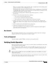
...shelf, or a wall, as described in the "Installing the Switch" section on Cisco.com describes the box contents. and 48-Port Switches)." POST lasts approximately 1 minute. Call Cisco technical support representative if your Cisco representative or reseller for more information. After a successful POST, disconnect the power ... to the AC power connector on page 1-13 for support. To power on the switch, connect one end of the AC power cord to the Catalyst 2960 8-port switches. You can receive power from Cisco. Verifying Switch Operation Before installing the switch in a ...
...shelf, or a wall, as described in the "Installing the Switch" section on Cisco.com describes the box contents. and 48-Port Switches)." POST lasts approximately 1 minute. Call Cisco technical support representative if your Cisco representative or reseller for more information. After a successful POST, disconnect the power ... to the AC power connector on page 1-13 for support. To power on the switch, connect one end of the AC power cord to the Catalyst 2960 8-port switches. You can receive power from Cisco. Verifying Switch Operation Before installing the switch in a ...
Hardware Installation Guide
Page 74
Contact your Cisco technical support representative if your switch does not pass POST. In these sections when troubleshooting switch connectivity problems: • Bad or Damaged Cable, page 4-2 • Ethernet and Fiber Cables, page 4-3 • Link Status, page 4-3 • Transceiver Module Port Issues, page 4-3 • Port and Interface Settings, page 4-4 • Ping the End Device...
Contact your Cisco technical support representative if your switch does not pass POST. In these sections when troubleshooting switch connectivity problems: • Bad or Damaged Cable, page 4-2 • Ethernet and Fiber Cables, page 4-3 • Link Status, page 4-3 • Transceiver Module Port Issues, page 4-3 • Port and Interface Settings, page 4-4 • Ping the End Device...

Hardware Installation Guide
Page 75
... light for the port does not come on: • Connect the cable from the switch to a known, good device. • Make sure that both ends of supported SFP modules. • Use the show link, but is not. A single broken wire or one shutdown port can cause one side to show interfaces privileged...-through cable was required or the reverse. Make sure that the ports on the switch, or replace the cable. Transceiver Module Port Issues Use only Cisco small form-factor (SFP) modules on page 1-1 for a list of the cable are using the correct cable type. OL-7075-09 Catalyst 2960 Switch Hardware...
... light for the port does not come on: • Connect the cable from the switch to a known, good device. • Make sure that both ends of supported SFP modules. • Use the show link, but is not. A single broken wire or one shutdown port can cause one side to show interfaces privileged...-through cable was required or the reverse. Make sure that the ports on the switch, or replace the cable. Transceiver Module Port Issues Use only Cisco small form-factor (SFP) modules on page 1-1 for a list of the cable are using the correct cable type. OL-7075-09 Catalyst 2960 Switch Hardware...
Hardware Installation Guide
Page 76
If a port or interface is used repeatedly by trunk, until you find unidirectional link problems. UDLD supports a normal mode of the connectivity issue. Use the show a large number of alignment errors, frame check sequence (FCS), or late-collisions errors...of autonegotiation issues between the switch and a workstation or server. Catalyst 2960 Switch Hardware Installation Guide 4-4 OL-7075-09 Ping the End Device Verify the end device connection by one -way communication. This can cause loops. In aggressive mode, UDLD also detects unidirectional links caused by first ...
If a port or interface is used repeatedly by trunk, until you find unidirectional link problems. UDLD supports a normal mode of the connectivity issue. Use the show a large number of alignment errors, frame check sequence (FCS), or late-collisions errors...of autonegotiation issues between the switch and a workstation or server. Catalyst 2960 Switch Hardware Installation Guide 4-4 OL-7075-09 Ping the End Device Verify the end device connection by one -way communication. This can cause loops. In aggressive mode, UDLD also detects unidirectional links caused by first ...
Hardware Installation Guide
Page 98
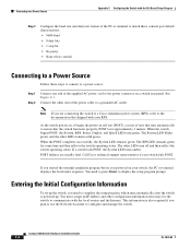
... • None (flow control) Connecting to a Power Source Follow these steps to connect to a power source: Step 1 Step 2 Connect one end of tests that runs automatically to ensure that shipped with your switch fails POST. Connect the other LEDs turn green. This information is powered up...power connector on self test (POST), a series of the supplied AC power cord to the documentation that the switch functions properly. Call Cisco technical support representative if your RPS. You must assign an IP address and other LEDs remain solid green. See Figure C-1. If a switch fails...
... • None (flow control) Connecting to a Power Source Follow these steps to connect to a power source: Step 1 Step 2 Connect one end of tests that runs automatically to ensure that shipped with your switch fails POST. Connect the other LEDs turn green. This information is powered up...power connector on self test (POST), a series of the supplied AC power cord to the documentation that the switch functions properly. Call Cisco technical support representative if your RPS. You must assign an IP address and other LEDs remain solid green. See Figure C-1. If a switch fails...

Hardware Installation Guide
Page 107
...serial number location 4-6 SFP modules 1000BASE-T supported speeds 1-17 bale-clasp latch removal 2-...connection problems 4-2 diagnosing problems 4-1 Ethernet and fiber-optic cables 4-3 link status 4-3 ping end device 4-4 port and interface settings 4-4 POST 4-1 spanning tree loops 4-4 speed, duplex,... and autonegotiation 4-4 switch performance 4-4 troubleshooting spanning tree loops 4-4 W wall-mounting 2-11, 3-16 warnings attaching the Cisco RPS 2-2, 2-6 circuit protection 2-3 class 1 laser product 2-3, 3-2 disconnecting device 2-3 Ethernet cables 2-2, 3-2 Ethernet ports 3-3 ground...
...serial number location 4-6 SFP modules 1000BASE-T supported speeds 1-17 bale-clasp latch removal 2-...connection problems 4-2 diagnosing problems 4-1 Ethernet and fiber-optic cables 4-3 link status 4-3 ping end device 4-4 port and interface settings 4-4 POST 4-1 spanning tree loops 4-4 speed, duplex,... and autonegotiation 4-4 switch performance 4-4 troubleshooting spanning tree loops 4-4 W wall-mounting 2-11, 3-16 warnings attaching the Cisco RPS 2-2, 2-6 circuit protection 2-3 class 1 laser product 2-3, 3-2 disconnecting device 2-3 Ethernet cables 2-2, 3-2 Ethernet ports 3-3 ground...


