

Hardware Installation Guide
Page 2
... between Cisco and any interference to cause harmful interference, in which case users will not occur in accordance with the instruction manual, may be limited by using one side or the other trademarks mentioned in a commercial environment. THE SPECIFICATIONS AND INFORMATION REGARDING THE PRODUCTS IN THIS MANUAL ARE SUBJECT TO CHANGE WITHOUT NOTICE. Catalyst 2960 Switch Hardware Installation Guide © 2005-2010 Cisco Systems...
... between Cisco and any interference to cause harmful interference, in which case users will not occur in accordance with the instruction manual, may be limited by using one side or the other trademarks mentioned in a commercial environment. THE SPECIFICATIONS AND INFORMATION REGARDING THE PRODUCTS IN THIS MANUAL ARE SUBJECT TO CHANGE WITHOUT NOTICE. Catalyst 2960 Switch Hardware Installation Guide © 2005-2010 Cisco Systems...

Hardware Installation Guide
Page 21
...-T SFP module port on the switch, regardless of the type of device on the other end of the attached device and advertises its own capabilities. When you connect the switch to workstations, servers, routers, and Cisco IP Phones, be within 328 feet (100 meters). 100BASE-TX and 1000BASE-T traffic requires a Category 5 or higher cable. 10BASE-T traffic can also set these ports for this feature, see the switch software configuration guide or the switch command reference...
...-T SFP module port on the switch, regardless of the type of device on the other end of the attached device and advertises its own capabilities. When you connect the switch to workstations, servers, routers, and Cisco IP Phones, be within 328 feet (100 meters). 100BASE-TX and 1000BASE-T traffic requires a Category 5 or higher cable. 10BASE-T traffic can also set these ports for this feature, see the switch software configuration guide or the switch command reference...
Hardware Installation Guide
Page 22
The Catalyst 2960-24PC-L, 2960-48PST-L, 2960-48PST-S, and 2960-24PC-S switches deliver a maximum power output of security. The device manager, Network Assistant, and the CLI provide PoE settings for the powered device. Never: When you select the Never setting, the port does not provide power even if a Cisco IP phone or an access point is the default. - In that do not fully support IEEE 802.3af, might not support PoE when connected to an...
The Catalyst 2960-24PC-L, 2960-48PST-L, 2960-48PST-S, and 2960-24PC-S switches deliver a maximum power output of security. The device manager, Network Assistant, and the CLI provide PoE settings for the powered device. Never: When you select the Never setting, the port does not provide power even if a Cisco IP phone or an access point is the default. - In that do not fully support IEEE 802.3af, might not support PoE when connected to an...

Hardware Installation Guide
Page 23
... use Category 5 or higher cable with IEEE 802.3af). (See Figure 1-21.) 2. However, you insert an SFP module. Chapter 1 Product Overview Front Panel Description SFP Module Slots The Catalyst 2960 switches (other switches. For more information about configuring speed and duplex settings for Gigabit uplink connections to other than those listed) use the media-type interface configuration command to manually select the RJ-45 connector or the SFP module connector. Each uplink port has two LEDs...
... use Category 5 or higher cable with IEEE 802.3af). (See Figure 1-21.) 2. However, you insert an SFP module. Chapter 1 Product Overview Front Panel Description SFP Module Slots The Catalyst 2960 switches (other switches. For more information about configuring speed and duplex settings for Gigabit uplink connections to other than those listed) use the media-type interface configuration command to manually select the RJ-45 connector or the SFP module connector. Each uplink port has two LEDs...

Hardware Installation Guide
Page 32
..., can be downloaded from the CLI. The software configuration guide also provides examples of network configuration concepts. For more information, see the Getting Started with centralized management of Cisco LAN switches, core switches, routers, access points, IP phones, and PIX firewalls. See the Catalyst 2960 Switch Command Reference on Cisco.com for more information. • SNMP network management You can use SNMP management applications such as HP OpenView or SunNet Manager. The Cisco Configuration Engine is a network management device that works with the CLI-Based Setup Program...
..., can be downloaded from the CLI. The software configuration guide also provides examples of network configuration concepts. For more information, see the Getting Started with centralized management of Cisco LAN switches, core switches, routers, access points, IP phones, and PIX firewalls. See the Catalyst 2960 Switch Command Reference on Cisco.com for more information. • SNMP network management You can use SNMP management applications such as HP OpenView or SunNet Manager. The Cisco Configuration Engine is a network management device that works with the CLI-Based Setup Program...

Hardware Installation Guide
Page 34
... system. If the chassis falls, it in a central office environment. Statement 48 Warning Ethernet cables must be shielded when used in an area that is not connected to power lines, remove jewelry (including rings, necklaces, and watches). Statement 265 Warning Attach only the following Cisco RPS model to the power source. Statement 1001 Warning Read the installation instructions before beginning installation. To prevent airflow...
... system. If the chassis falls, it in a central office environment. Statement 48 Warning Ethernet cables must be shielded when used in an area that is not connected to power lines, remove jewelry (including rings, necklaces, and watches). Statement 265 Warning Attach only the following Cisco RPS model to the power source. Statement 1001 Warning Read the installation instructions before beginning installation. To prevent airflow...
Hardware Installation Guide
Page 36
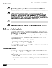
... a restricted access location and users and service people who are authorized within the restricted access location are equipped with local and national electrical codes. Catalyst 2960 Switch Hardware Installation Guide 2-4 OL-7075-09 Statement 1072 Warning No user-serviceable parts inside the chassis, which lists the cable specifications for 1000BASE-X and 100BASE-X SFP modules for the Catalyst 2960-8TC-L, 2960-8TC-S, 2960G-8TC-L, and 2960PD-8TT-L switches. Preparing for Particulate Matter Cisco Ethernet switches are...
... a restricted access location and users and service people who are authorized within the restricted access location are equipped with local and national electrical codes. Catalyst 2960 Switch Hardware Installation Guide 2-4 OL-7075-09 Statement 1072 Warning No user-serviceable parts inside the chassis, which lists the cable specifications for 1000BASE-X and 100BASE-X SFP modules for the Catalyst 2960-8TC-L, 2960-8TC-S, 2960G-8TC-L, and 2960PD-8TT-L switches. Preparing for Particulate Matter Cisco Ethernet switches are...

Hardware Installation Guide
Page 38
... filled rack, load the rack from the switch. The following Cisco RPS model to those switches, see Chapter 3, "Switch Installation (8-Port Switches)." LEDs can blink during the test. The System LED blinks green, and the other LEDs turn green. The RPS LED remains green for some time and then reflects the switch operating status. and 48-port switches. This section describes these installation procedures: • Rack-Mounting, page 2-6 • Wall-Mounting, page 2-11 • Table- Warning To prevent bodily injury when mounting or servicing...
... filled rack, load the rack from the switch. The following Cisco RPS model to those switches, see Chapter 3, "Switch Installation (8-Port Switches)." LEDs can blink during the test. The System LED blinks green, and the other LEDs turn green. The RPS LED remains green for some time and then reflects the switch operating status. and 48-port switches. This section describes these installation procedures: • Rack-Mounting, page 2-6 • Wall-Mounting, page 2-11 • Table- Warning To prevent bodily injury when mounting or servicing...
Hardware Installation Guide
Page 45
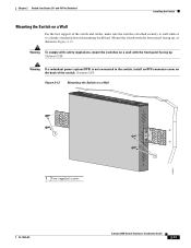
...-Port Switches) Installing the Switch Mounting the Switch on the back of the switch. Chapter 2 Switch Installation (24- Mount the switch with the front panel facing up , as shown in Figure 2-12. Statement 266 Warning If a redundant power system (RPS) is attached securely to wall studs or to the switch, install an RPS connector cover on a Wall For the best support of the switch and cables, make sure the switch...
...-Port Switches) Installing the Switch Mounting the Switch on the back of the switch. Chapter 2 Switch Installation (24- Mount the switch with the front panel facing up , as shown in Figure 2-12. Statement 266 Warning If a redundant power system (RPS) is attached securely to wall studs or to the switch, install an RPS connector cover on a Wall For the best support of the switch and cables, make sure the switch...

Hardware Installation Guide
Page 47
...2X MODE 12X 204623 Step 2 Step 3 Step 4 Connect the other end of SFP modules that the Catalyst 2960 switch supports. The port LED turns on page B-4 for this feature, see the switch software configuration guide or the switch command reference. Refer to the Catalyst 2960 switch release notes for the list of the cable to cabling problems. Reconfigure and reboot the connected device if necessary. See Chapter 4, "Troubleshooting," for cable OL-7075-09 Catalyst 2960 Switch Hardware Installation Guide 2-15 Chapter 2 Switch Installation (24- and 48-Port Switches) Installing...
...2X MODE 12X 204623 Step 2 Step 3 Step 4 Connect the other end of SFP modules that the Catalyst 2960 switch supports. The port LED turns on page B-4 for this feature, see the switch software configuration guide or the switch command reference. Refer to the Catalyst 2960 switch release notes for the list of the cable to cabling problems. Reconfigure and reboot the connected device if necessary. See Chapter 4, "Troubleshooting," for cable OL-7075-09 Catalyst 2960 Switch Hardware Installation Guide 2-15 Chapter 2 Switch Installation (24- and 48-Port Switches) Installing...
Hardware Installation Guide
Page 48
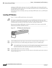
For detailed instructions on installing, removing, and cabling the SFP module, refer to a bare metal surface on the chassis. Insert the SFP module into place in front of the slot opening. See Figure 2-15. 2-16 Catalyst 2960 Switch Hardware Installation Guide OL-7075-09 Caution We strongly recommend that identify the top side of the connection, either send or receive (TX or RX). Note On some SFP modules, the send...
For detailed instructions on installing, removing, and cabling the SFP module, refer to a bare metal surface on the chassis. Insert the SFP module into place in front of the slot opening. See Figure 2-15. 2-16 Catalyst 2960 Switch Hardware Installation Guide OL-7075-09 Caution We strongly recommend that identify the top side of the connection, either send or receive (TX or RX). Note On some SFP modules, the send...
Hardware Installation Guide
Page 57
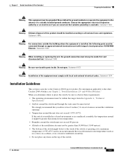
OL-7075-09 Catalyst 2960 Switch Hardware Installation Guide 3-3 Statement 1040. Statement 1046 Warning No user-serviceable parts inside. Statement 1074 Installation Guidelines This section is specific to the touch if the switch is operating at its maximum temperature 113°F (45°C) and is installed in a multirack assembly, the temperature around it might be greater than normal room temperature. • Humidity around...
OL-7075-09 Catalyst 2960 Switch Hardware Installation Guide 3-3 Statement 1040. Statement 1046 Warning No user-serviceable parts inside. Statement 1074 Installation Guidelines This section is specific to the touch if the switch is operating at its maximum temperature 113°F (45°C) and is installed in a multirack assembly, the temperature around it might be greater than normal room temperature. • Humidity around...
Hardware Installation Guide
Page 73
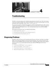
... Catalyst 2960 Switch Hardware Installation Guide 4-1 This chapter describes these topics for details. Troubleshooting 4 C H A P T E R The LEDs on the front panel provide troubleshooting information about the switch. You can also get statistics from the browser interface, from the command-line interface (CLI), or from an SNMP workstation. They show failures in the power-on page 1-14. See the software configuration guide, the switch command reference guide on Cisco.com, or the documentation that came with your SNMP application for troubleshooting problems...
... Catalyst 2960 Switch Hardware Installation Guide 4-1 This chapter describes these topics for details. Troubleshooting 4 C H A P T E R The LEDs on the front panel provide troubleshooting information about the switch. You can also get statistics from the browser interface, from the command-line interface (CLI), or from an SNMP workstation. They show failures in the power-on page 1-14. See the software configuration guide, the switch command reference guide on Cisco.com, or the documentation that came with your SNMP application for troubleshooting problems...

Hardware Installation Guide
Page 75
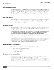
... both devices have power. • Verify that you are using the correct cable type. If the link light for the port does not come on the switch, or replace the cable. Exchange the suspect module with security information. Transceiver Module Port Issues Use only Cisco small form-factor (SFP) modules on the connected device match and that they use Category 3 copper cable for 10 Mb/s unshielded twisted pair (UTP) connections. Chapter 4 Troubleshooting Diagnosing Problems Ethernet and Fiber Cables Make...
... both devices have power. • Verify that you are using the correct cable type. If the link light for the port does not come on the switch, or replace the cable. Exchange the suspect module with security information. Transceiver Module Port Issues Use only Cisco small form-factor (SFP) modules on the connected device match and that they use Category 3 copper cable for 10 Mb/s unshielded twisted pair (UTP) connections. Chapter 4 Troubleshooting Diagnosing Problems Ethernet and Fiber Cables Make...
Hardware Installation Guide
Page 76
... its Content-Addressable Memory (CAM) table. Diagnosing Problems Chapter 4 Troubleshooting Port and Interface Settings An obvious but the switch does not receive the traffic that each switch can identify the end device MAC address in the software configuration guide. A broken fiber-optic cable, other cabling, or a port issue could cause this situation, the switch bandwidth is manually shut down on one -way communication. If a port or interface is used repeatedly by trunk, until you troubleshoot switch performance problems: • Speed, Duplex...
... its Content-Addressable Memory (CAM) table. Diagnosing Problems Chapter 4 Troubleshooting Port and Interface Settings An obvious but the switch does not receive the traffic that each switch can identify the end device MAC address in the software configuration guide. A broken fiber-optic cable, other cabling, or a port issue could cause this situation, the switch bandwidth is manually shut down on one -way communication. If a port or interface is used repeatedly by trunk, until you troubleshoot switch performance problems: • Speed, Duplex...
Hardware Installation Guide
Page 77
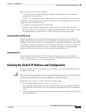
... cable distance from the switch to manually set both sides of the connection. • If a remote device does not autonegotiate, configure the duplex settings on the switch. The switch LEDs begin blinking after an additional 8 seconds, and then the switch reboots. The LEDs stop blinking after about 2 seconds. Upgrade the NIC card driver to the factory default settings: 1. You can omit this does not solve the problem, the firmware or software on your switch to the latest version...
... cable distance from the switch to manually set both sides of the connection. • If a remote device does not autonegotiate, configure the duplex settings on the switch. The switch LEDs begin blinking after an additional 8 seconds, and then the switch reboots. The LEDs stop blinking after about 2 seconds. Upgrade the NIC card driver to the factory default settings: 1. You can omit this does not solve the problem, the firmware or software on your switch to the latest version...
Hardware Installation Guide
Page 95
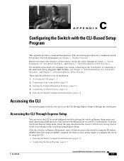
... the Catalyst 2960 Switch Getting Started Guide for powering on an unconfigured switch by using the IP address 10.0.0.1. Connecting to a Power Source, page C-4 5. Accessing the CLI Through Express Setup You can access the CLI through Express Setup or through the console port. After the switch is in this chapter to the small form-factor pluggable (SFP) modules, see Chapter 1, "Product Overview." See these sections in Express Setup mode, open a Telnet session to the Ethernet port of your switch, connecting...
... the Catalyst 2960 Switch Getting Started Guide for powering on an unconfigured switch by using the IP address 10.0.0.1. Connecting to a Power Source, page C-4 5. Accessing the CLI Through Express Setup You can access the CLI through Express Setup or through the console port. After the switch is in this chapter to the small form-factor pluggable (SFP) modules, see Chapter 1, "Product Overview." See these sections in Express Setup mode, open a Telnet session to the Ethernet port of your switch, connecting...
Hardware Installation Guide
Page 98
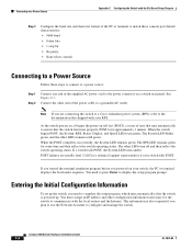
... these console port default characteristics: • 9600 baud • 8 data bits • 1 stop bit • No parity • None (flow control) Connecting to a Power Source Follow these steps to connect to a power source: Step 1 Step 2 Connect one end of the power cable to a grounded AC outlet. Catalyst 2960 Switch Hardware Installation Guide C-4 OL-7075-09 You must assign an IP address and other LEDs remain solid green. The System LED blinks green...
... these console port default characteristics: • 9600 baud • 8 data bits • 1 stop bit • No parity • None (flow control) Connecting to a Power Source Follow these steps to connect to a power source: Step 1 Step 2 Connect one end of the power cable to a grounded AC outlet. Catalyst 2960 Switch Hardware Installation Guide C-4 OL-7075-09 You must assign an IP address and other LEDs remain solid green. The System LED blinks green...

Hardware Installation Guide
Page 104
...dual-purpose ports 1-13 LEDs 1-14 to configure switch 2-21, 3-18 diagnosing problems 4-1 disconnecting device warning 2-3 dual-purpose ports connectors and cables B-3 described 1-13 LEDs 1-18 duplex, troubleshooting 4-4 duplex LED 1-16 E electrical noise, avoiding 2-5, 3-4 Ethernet and fiber-optic cable troubleshooting 4-3 Ethernet cable warning 24- Index Cisco IP Phones, connecting to 1-12, 2-15 Cisco RPS See RPS CiscoView 1-22 class 1 laser warning 2-3, 3-2 CLI accessing by using Express Setup C-1 accessing through console port C-2 described 1-22 command-line interface See CLI compliance...
...dual-purpose ports 1-13 LEDs 1-14 to configure switch 2-21, 3-18 diagnosing problems 4-1 disconnecting device warning 2-3 dual-purpose ports connectors and cables B-3 described 1-13 LEDs 1-18 duplex, troubleshooting 4-4 duplex LED 1-16 E electrical noise, avoiding 2-5, 3-4 Ethernet and fiber-optic cable troubleshooting 4-3 Ethernet cable warning 24- Index Cisco IP Phones, connecting to 1-12, 2-15 Cisco RPS See RPS CiscoView 1-22 class 1 laser warning 2-3, 3-2 CLI accessing by using Express Setup C-1 accessing through console port C-2 described 1-22 command-line interface See CLI compliance...

Hardware Installation Guide
Page 107
... twisted-pair 10/100 ports B-6 SunNet Manager 1-22 switch descriptions 1-1 switch powering on 2-5, 3-5 system LED 1-15 T technical specifications A-1 telco racks 2-7, 3-15 Telnet, and accessing the CLI 1-22 temperature, operating A-1 terminal emulation software C-3 trained and qualified personnel warning 2-3 troubleshooting 4-1 to 4-6 OL-7075-09 Index bad or damaged cable 4-2 connection problems 4-2 diagnosing problems 4-1 Ethernet and fiber-optic cables 4-3 link status 4-3 ping end device 4-4 port and interface settings 4-4 POST 4-1 spanning tree loops 4-4 speed, duplex, and autonegotiation...
... twisted-pair 10/100 ports B-6 SunNet Manager 1-22 switch descriptions 1-1 switch powering on 2-5, 3-5 system LED 1-15 T technical specifications A-1 telco racks 2-7, 3-15 Telnet, and accessing the CLI 1-22 temperature, operating A-1 terminal emulation software C-3 trained and qualified personnel warning 2-3 troubleshooting 4-1 to 4-6 OL-7075-09 Index bad or damaged cable 4-2 connection problems 4-2 diagnosing problems 4-1 Ethernet and fiber-optic cables 4-3 link status 4-3 ping end device 4-4 port and interface settings 4-4 POST 4-1 spanning tree loops 4-4 speed, duplex, and autonegotiation...


