

Hardware Installation Guide
Page 4
... Matter 2-4 Installation Guidelines 2-4 Box Contents 2-5 Tools and Equipment 2-5 Verifying Switch Operation 2-5 Installing the Switch 2-6 Rack-Mounting 2-6 Removing Screws from the Switch 2-7 Attaching Brackets to the Catalyst 2960 Switch 2-7 Mounting the Switch in a Rack 2-10 Attaching the Cable Guide 2-11 Wall-Mounting 2-11 Attaching the Brackets to Go Next 2-21 Switch Installation (8-Port Switches) 3-1 Preparing for...
... Matter 2-4 Installation Guidelines 2-4 Box Contents 2-5 Tools and Equipment 2-5 Verifying Switch Operation 2-5 Installing the Switch 2-6 Rack-Mounting 2-6 Removing Screws from the Switch 2-7 Attaching Brackets to the Catalyst 2960 Switch 2-7 Mounting the Switch in a Rack 2-10 Attaching the Cable Guide 2-11 Wall-Mounting 2-11 Attaching the Brackets to Go Next 2-21 Switch Installation (8-Port Switches) 3-1 Preparing for...

Hardware Installation Guide
Page 5
... P T E R A A P P E N D I X B A P P E N D I X OL-7075-09 Desk- or Shelf-Mounting (with Rack-Mount Brackets) 3-16 Where to Go Next 3-18 Troubleshooting 4-1 Diagnosing Problems 4-1 Verify Switch POST Results 4-2 Monitor Switch LEDs 4-2 Verify Switch Connections 4-2 Bad or ... 2960 Switch Hardware Installation Guide v or Shelf-Mounting (with Mounting Screws) 3-8 Wall-Mounting (with Mounting Screws) 3-11 Magnet Mounting 3-14 Rack-Mounting 3-15 Attaching Brackets to the Switch 3-15 Mounting the Switch in a 19-Inch Rack 3-16 Wall-Mounting (with Mounting Screws) 3-7 Under the Desk- or Shelf...
... P T E R A A P P E N D I X B A P P E N D I X OL-7075-09 Desk- or Shelf-Mounting (with Rack-Mount Brackets) 3-16 Where to Go Next 3-18 Troubleshooting 4-1 Diagnosing Problems 4-1 Verify Switch POST Results 4-2 Monitor Switch LEDs 4-2 Verify Switch Connections 4-2 Bad or ... 2960 Switch Hardware Installation Guide v or Shelf-Mounting (with Mounting Screws) 3-8 Wall-Mounting (with Mounting Screws) 3-11 Magnet Mounting 3-14 Rack-Mounting 3-15 Attaching Brackets to the Switch 3-15 Mounting the Switch in a 19-Inch Rack 3-16 Wall-Mounting (with Mounting Screws) 3-7 Under the Desk- or Shelf...
Hardware Installation Guide
Page 35
...national laws and regulations. Statement 1008 Warning This unit is intended for Installation Warning To prevent bodily injury when mounting or servicing this unit in the rack. Statement 1019 Warning This equipment must take special precautions to install, replace, or service this unit in .... All connections must be allowed to ensure that suitable grounding is provided with stabilizing devices, install the stabilizers before mounting or servicing the unit in a rack, you are provided to ensure your safety: • This unit should be connected through the use of a ...
...national laws and regulations. Statement 1008 Warning This unit is intended for Installation Warning To prevent bodily injury when mounting or servicing this unit in the rack. Statement 1019 Warning This equipment must take special precautions to install, replace, or service this unit in .... All connections must be allowed to ensure that suitable grounding is provided with stabilizing devices, install the stabilizers before mounting or servicing the unit in a rack, you are provided to ensure your safety: • This unit should be connected through the use of a ...
Hardware Installation Guide
Page 37
... of an AC power receptacle. • Cabling is safely away from sources of the power cord to rack-mount the switch. See Chapter 3, "Switch Installation (8-Port Switches)," and see the Cisco RPS documentation for unrestricted cabling. - To power on the switch, connect one end of single-mode fiber... temperature. Box Contents The switch getting started guide on the switch, and connect the other devices that the switch passes POST. If your Cisco representative or reseller for support. Note When you might damage the cables. • Airflow around the unit does not exceed 113°F ...
... of an AC power receptacle. • Cabling is safely away from sources of the power cord to rack-mount the switch. See Chapter 3, "Switch Installation (8-Port Switches)," and see the Cisco RPS documentation for unrestricted cabling. - To power on the switch, connect one end of single-mode fiber... temperature. Box Contents The switch getting started guide on the switch, and connect the other devices that the switch passes POST. If your Cisco representative or reseller for support. Note When you might damage the cables. • Airflow around the unit does not exceed 113°F ...

Hardware Installation Guide
Page 38
...operating status. When the POST completes successfully, the System LED remains green. Call Cisco technical support representative if your safety: • This unit should be mounted at the bottom of tests that runs automatically to the RPS receptacle: PWR-RPS2300... the switch functions properly. For information applicable to those switches, see Chapter 3, "Switch Installation (8-Port Switches)." or Shelf-Mounting, page 2-14 Rack-Mounting This section applies to ensure your switch fails POST. For information applicable to those switches, see Chapter 3, "Switch Installation ...
...operating status. When the POST completes successfully, the System LED remains green. Call Cisco technical support representative if your safety: • This unit should be mounted at the bottom of tests that runs automatically to the RPS receptacle: PWR-RPS2300... the switch functions properly. For information applicable to those switches, see Chapter 3, "Switch Installation (8-Port Switches)." or Shelf-Mounting, page 2-14 Rack-Mounting This section applies to ensure your switch fails POST. For information applicable to those switches, see Chapter 3, "Switch Installation ...

Hardware Installation Guide
Page 39
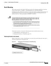
... 2960 Switch, page 2-7 • Mounting the Switch in a 24-inch rack. Follow the same steps to attach the second bracket to install the switch in a rack, you are attaching the brackets for a 19-inch or a 24-inch rack. Removing Screws from Cisco by using part number RCKMNT-1RU=. ...OL-7075-09 Catalyst 2960 Switch Hardware Installation Guide 2-7 Figure 2-2 to Figure 2-7 show how to attach each type of bracket to remove the chassis screws in the switch chassis so that contains the 24-inch rack-mounting ...
... 2960 Switch, page 2-7 • Mounting the Switch in a 24-inch rack. Follow the same steps to attach the second bracket to install the switch in a rack, you are attaching the brackets for a 19-inch or a 24-inch rack. Removing Screws from Cisco by using part number RCKMNT-1RU=. ...OL-7075-09 Catalyst 2960 Switch Hardware Installation Guide 2-7 Figure 2-2 to Figure 2-7 show how to attach each type of bracket to remove the chassis screws in the switch chassis so that contains the 24-inch rack-mounting ...
Hardware Installation Guide
Page 42
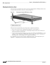
...screws to securely attach the brackets to complete the installation. Figure 2-8 Mounting the Catalyst 2960 Switch in a Rack 204618 SYST RPS STAT DUPLX SPEED MODE 1 1 Phillips machine screws After the switch is mounted in the rack, do these tasks to Appendix C, "Configuring the Switch with the CLI...-Based Setup Program." 2-10 Catalyst 2960 Switch Hardware Installation Guide OL-7075-09 and 48-Port Switches) Mounting the Switch in Figure 2-8. See the "...
...screws to securely attach the brackets to complete the installation. Figure 2-8 Mounting the Catalyst 2960 Switch in a Rack 204618 SYST RPS STAT DUPLX SPEED MODE 1 1 Phillips machine screws After the switch is mounted in the rack, do these tasks to Appendix C, "Configuring the Switch with the CLI...-Based Setup Program." 2-10 Catalyst 2960 Switch Hardware Installation Guide OL-7075-09 and 48-Port Switches) Mounting the Switch in Figure 2-8. See the "...
Hardware Installation Guide
Page 43
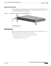
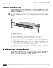
Use the supplied black screw shown in the rack. For information applicable to the left or right bracket. Figure 2-9 Attaching the Cable Guide... the instructions in these sections: • Attaching the Brackets to the Switch for Wall-Mounting, page 2-12 • Attaching the RPS Connector Cover, page 2-12 • Mounting the Switch on the Catalyst 2960 Switch 1 SYST RPS STAT DUPLX SPEED MODE 204619 ...1 Cable guide screw Wall-Mounting This section does not apply to prevent the cables from obscuring the front panel of the ...
Use the supplied black screw shown in the rack. For information applicable to the left or right bracket. Figure 2-9 Attaching the Cable Guide... the instructions in these sections: • Attaching the Brackets to the Switch for Wall-Mounting, page 2-12 • Attaching the RPS Connector Cover, page 2-12 • Mounting the Switch on the Catalyst 2960 Switch 1 SYST RPS STAT DUPLX SPEED MODE 204619 ...1 Cable guide screw Wall-Mounting This section does not apply to prevent the cables from obscuring the front panel of the ...

Hardware Installation Guide
Page 56
...the bottom of the rack if it is the only unit in the rack. • When mounting this unit in a rack, you must be shielded when used in the rack. Statement 1004 Warning To prevent bodily injury when mounting or servicing this unit in a partially filled rack, load the rack from the bottom ... Catalyst 2960PD-8TT-L switch: Warning This product must be connected to the power source. If the chassis falls, it serves as the main disconnecting device. Statement 1008 Warning The plug-socket combination must be accessible at the bottom of the rack. • If the rack is connected ...
...the bottom of the rack if it is the only unit in the rack. • When mounting this unit in a rack, you must be shielded when used in the rack. Statement 1004 Warning To prevent bodily injury when mounting or servicing this unit in a partially filled rack, load the rack from the bottom ... Catalyst 2960PD-8TT-L switch: Warning This product must be connected to the power source. If the chassis falls, it serves as the main disconnecting device. Statement 1008 Warning The plug-socket combination must be accessible at the bottom of the rack. • If the rack is connected ...
Hardware Installation Guide
Page 58
...switches. To order a cable guard, contact your Cisco representative and use to manage a large number of cables in a rack on switches other than the Catalyst 2960-8TC-L... from each other. • Allow at each switch in the rack. • Do not wall-mount the switch with its front panel facing down to prevent airflow restriction... and to provide easier access to the cables. • Clearance to the switch front and rear panels meets these part numbers: • Catalyst 2960-8TC-L, 2960-8TC-S, and 2960PD-8TT...
...switches. To order a cable guard, contact your Cisco representative and use to manage a large number of cables in a rack on switches other than the Catalyst 2960-8TC-L... from each other. • Allow at each switch in the rack. • Do not wall-mount the switch with its front panel facing down to prevent airflow restriction... and to provide easier access to the cables. • Clearance to the switch front and rear panels meets these part numbers: • Catalyst 2960-8TC-L, 2960-8TC-S, and 2960PD-8TT...
Hardware Installation Guide
Page 59
...Installing the Switch" section on Cisco.com describes the box contents. This section describes these installation procedures: • Desk- POST failures are usually fatal. or Shelf-Mounting (without Mounting Screws), page 3-6 • Desk- You can order a kit containing the 19-inch rack-mounting brackets and hardware from an... terminal to rack-mount the switch. To power on the switch and verify that it begins the POST, a series of the AC power cord to the Catalyst 2960 8-port switches. You can blink during the test. See the "Power Input Port (Catalyst 2960PD-8TT-L Switch)" ...
...Installing the Switch" section on Cisco.com describes the box contents. This section describes these installation procedures: • Desk- POST failures are usually fatal. or Shelf-Mounting (without Mounting Screws), page 3-6 • Desk- You can order a kit containing the 19-inch rack-mounting brackets and hardware from an... terminal to rack-mount the switch. To power on the switch and verify that it begins the POST, a series of the AC power cord to the Catalyst 2960 8-port switches. You can blink during the test. See the "Power Input Port (Catalyst 2960PD-8TT-L Switch)" ...

Hardware Installation Guide
Page 60
or Shelf-Mounting (with Mounting Screws), page 3-8 • Wall-Mounting (with Mounting Screws), page 3-11 • Magnet Mounting, page 3-14 • Rack-Mounting, page 3-15 • Wall-Mounting (with the CLI-Based Setup Program." or Shelf-Mounting (without mounting screws. If you attach the rubber feet. This prevents the switch... Step 3 Place the switch on the desk or shelf, do not want to use the mounting screws, follow these tasks to Appendix C, "Configuring the Switch with Rack-Mount Brackets), page 3-16 Desk- After the switch is specific to the other . Connect to ...
or Shelf-Mounting (with Mounting Screws), page 3-8 • Wall-Mounting (with Mounting Screws), page 3-11 • Magnet Mounting, page 3-14 • Rack-Mounting, page 3-15 • Wall-Mounting (with the CLI-Based Setup Program." or Shelf-Mounting (without mounting screws. If you attach the rubber feet. This prevents the switch... Step 3 Place the switch on the desk or shelf, do not want to use the mounting screws, follow these tasks to Appendix C, "Configuring the Switch with Rack-Mount Brackets), page 3-16 Desk- After the switch is specific to the other . Connect to ...
Hardware Installation Guide
Page 69
... to the Catalyst 2960 8-port switches. and 48-Port Switches)." Warning To prevent bodily injury when mounting or servicing this unit in a partially filled rack, load the rack from Cisco. Installing the Catalyst 2960 8-port switches in a rack, you must take special precautions to ensure that is not included with stabilizing devices, install the stabilizers...
... to the Catalyst 2960 8-port switches. and 48-Port Switches)." Warning To prevent bodily injury when mounting or servicing this unit in a partially filled rack, load the rack from Cisco. Installing the Catalyst 2960 8-port switches in a rack, you must take special precautions to ensure that is not included with stabilizing devices, install the stabilizers...
Hardware Installation Guide
Page 70
...with the CLI-Based Setup Program." Connect to complete the installation: 1. Power on page 3-5. 2. Wall-Mounting (with Rack-Mount Brackets) To install the Catalyst 2960 8-port switches in a 19-inch rack requires an optional bracket kit that you allow at least 1.75 inches (4 cm) of clearance above ...the switch, insert the switch into the 19-inch rack, and align the bracket in the rack. See the switch getting started guide for instructions. 3. You can order a kit containing the 19-inch rack-mounting brackets and hardware from Cisco. This section is RCKMNT-19-CMPCT=. For information ...
...with the CLI-Based Setup Program." Connect to complete the installation: 1. Power on page 3-5. 2. Wall-Mounting (with Rack-Mount Brackets) To install the Catalyst 2960 8-port switches in a 19-inch rack requires an optional bracket kit that you allow at least 1.75 inches (4 cm) of clearance above ...the switch, insert the switch into the 19-inch rack, and align the bracket in the rack. See the switch getting started guide for instructions. 3. You can order a kit containing the 19-inch rack-mounting brackets and hardware from Cisco. This section is RCKMNT-19-CMPCT=. For information ...

Hardware Installation Guide
Page 103
...racks 2-7, 3-15 A AC power connecting to 2-5, 3-5 connector 1-20 specifications A-2 to A-4 AC power adapter for Catalyst 2960PD-8TT-L...1000 ports cable lengths 2-4, 3-4 connecting to 2-14 connectors and cables B-1 to -DB-9 B-8 attaching the Cisco RPS warning 2-2, 2-6 auto-MDIX 1-11, 2-15, 2-20, B-1, B-3, C-2 autonegotiation 1-11 autonegotiation ...OL-7075-09 INDEX B bodily injury prevention warning 2-2, 3-2 bodily injury warning 2-3, 2-6, 3-2, 3-15 brackets See mounting brackets C cable guard 1-19, 3-4 cable guide, attaching 2-11 cable lengths 2-4, 3-3 cable lock 3-4 cables crossover...
...racks 2-7, 3-15 A AC power connecting to 2-5, 3-5 connector 1-20 specifications A-2 to A-4 AC power adapter for Catalyst 2960PD-8TT-L...1000 ports cable lengths 2-4, 3-4 connecting to 2-14 connectors and cables B-1 to -DB-9 B-8 attaching the Cisco RPS warning 2-2, 2-6 auto-MDIX 1-11, 2-15, 2-20, B-1, B-3, C-2 autonegotiation 1-11 autonegotiation ...OL-7075-09 INDEX B bodily injury prevention warning 2-2, 3-2 bodily injury warning 2-3, 2-6, 3-2, 3-15 brackets See mounting brackets C cable guard 1-19, 3-4 cable guide, attaching 2-11 cable lengths 2-4, 3-3 cable lock 3-4 cables crossover...
Hardware Installation Guide
Page 105
...4-2 lightning activity warning 2-2, 3-2 link status troubleshooting 4-3 M Mode button 1-14 model descriptions 1-1 mounting, desk or shelf 2-14, 3-6 mounting, wall-mounting 2-11, 3-16 mounting brackets attaching 2-7 to 2-9 rack-mount 2-10, 3-16 N Network Assistant described 1-22 to 2-10 in a rack (24- and 48-port switches) 2-11 on a wall (8-ports switches) 3-11 to 3-13... on a wall with rack-mount brackets (8-port switches) 3-16 on a wall (24- and 48-port switches) 2-7 to configure switch 2-21, 3-18 network configuration ...
...4-2 lightning activity warning 2-2, 3-2 link status troubleshooting 4-3 M Mode button 1-14 model descriptions 1-1 mounting, desk or shelf 2-14, 3-6 mounting, wall-mounting 2-11, 3-16 mounting brackets attaching 2-7 to 2-9 rack-mount 2-10, 3-16 N Network Assistant described 1-22 to 2-10 in a rack (24- and 48-port switches) 2-11 on a wall (8-ports switches) 3-11 to 3-13... on a wall with rack-mount brackets (8-port switches) 3-16 on a wall (24- and 48-port switches) 2-7 to configure switch 2-21, 3-18 network configuration ...
Hardware Installation Guide
Page 106
... supply AC power outlet 1-20 for the Catalyst 2960PD-8TT-L switch 1-13 internal 1-20 RPS connector 1-20 power supply warning 2-3, 3-3 procedures connection 2-14 to 2-20 installation 2-6 to 2-14, 3-5 to 3-18 product disposal warning 2-3, 3-3 R rack-mounting 2-7 to 2-10, 3-15 to 3-16 rack-mounting warning 2-3, 2-6, 3-2, 3-15 read the wall-mounting instructions warning 2-2, 3-11, 3-17 rear panel clearance 2-5, 3-4 description...
... supply AC power outlet 1-20 for the Catalyst 2960PD-8TT-L switch 1-13 internal 1-20 RPS connector 1-20 power supply warning 2-3, 3-3 procedures connection 2-14 to 2-20 installation 2-6 to 2-14, 3-5 to 3-18 product disposal warning 2-3, 3-3 R rack-mounting 2-7 to 2-10, 3-15 to 3-16 rack-mounting warning 2-3, 2-6, 3-2, 3-15 read the wall-mounting instructions warning 2-2, 3-11, 3-17 rear panel clearance 2-5, 3-4 description...

Hardware Installation Guide
Page 107
... Manager 1-22 switch descriptions 1-1 switch powering on 2-5, 3-5 system LED 1-15 T technical specifications A-1 telco racks 2-7, 3-15 Telnet, and accessing the CLI 1-22 temperature, operating A-1 terminal emulation software C-3 trained and ...settings 4-4 POST 4-1 spanning tree loops 4-4 speed, duplex, and autonegotiation 4-4 switch performance 4-4 troubleshooting spanning tree loops 4-4 W wall-mounting 2-11, 3-16 warnings attaching the Cisco RPS 2-2, 2-6 circuit protection 2-3 class 1 laser product 2-3, 3-2 disconnecting device 2-3 Ethernet cables 2-2, 3-2 Ethernet ports 3-3 ground connection...
... Manager 1-22 switch descriptions 1-1 switch powering on 2-5, 3-5 system LED 1-15 T technical specifications A-1 telco racks 2-7, 3-15 Telnet, and accessing the CLI 1-22 temperature, operating A-1 terminal emulation software C-3 trained and ...settings 4-4 POST 4-1 spanning tree loops 4-4 speed, duplex, and autonegotiation 4-4 switch performance 4-4 troubleshooting spanning tree loops 4-4 W wall-mounting 2-11, 3-16 warnings attaching the Cisco RPS 2-2, 2-6 circuit protection 2-3 class 1 laser product 2-3, 3-2 disconnecting device 2-3 Ethernet cables 2-2, 3-2 Ethernet ports 3-3 ground connection...
