Installation Guide
Page 2
... FOR THEIR APPLICATION OF ANY PRODUCTS. However, there is for Class A or Class B digital devices. Operation of California. THE SPECIFICATIONS AND INFORMATION REGARDING THE PRODUCTS IN THIS MANUAL ARE SUBJECT TO CHANGE WITHOUT NOTICE. Copyright © 1981, Regents of the University ...of this product not authorized by FCC regulations, and you may be required to correct any interference to operate the product. CISCO AND THE ABOVE-NAMED SUPPLIERS DISCLAIM ALL WARRANTIES, EXPRESSED OR IMPLIED, INCLUDING, WITHOUT LIMITATION, THOSE OF MERCHANTABILITY, FITNESS FOR A...
... FOR THEIR APPLICATION OF ANY PRODUCTS. However, there is for Class A or Class B digital devices. Operation of California. THE SPECIFICATIONS AND INFORMATION REGARDING THE PRODUCTS IN THIS MANUAL ARE SUBJECT TO CHANGE WITHOUT NOTICE. Copyright © 1981, Regents of the University ...of this product not authorized by FCC regulations, and you may be required to correct any interference to operate the product. CISCO AND THE ABOVE-NAMED SUPPLIERS DISCLAIM ALL WARRANTIES, EXPRESSED OR IMPLIED, INCLUDING, WITHOUT LIMITATION, THOSE OF MERCHANTABILITY, FITNESS FOR A...
Installation Guide
Page 8
...) C-2 Attaching the Cisco RPS (model PWR300-AC-RPS-N1) C-4 Service Personnel Warning C-5 Qualified Personnel Warning C-7 Installation Instructions Warning C-9 Jewelry Removal Warning C-10 Stacking the Chassis Warning C-13 Main Disconnecting Device C-15 Overtemperature Warning C-16 TN Power Warning C-19 Ground Connection Warning C-20 Circuit Breaker (15A) Warning C-21 Catalyst 3500 Series XL Hardware Installation...
...) C-2 Attaching the Cisco RPS (model PWR300-AC-RPS-N1) C-4 Service Personnel Warning C-5 Qualified Personnel Warning C-7 Installation Instructions Warning C-9 Jewelry Removal Warning C-10 Stacking the Chassis Warning C-13 Main Disconnecting Device C-15 Overtemperature Warning C-16 TN Power Warning C-19 Ground Connection Warning C-20 Circuit Breaker (15A) Warning C-21 Catalyst 3500 Series XL Hardware Installation...

Installation Guide
Page 12
...in screen font. • Information you enter is a physical and functional overview of the switch. Appendix A, "Technical Specifications," lists the physical and environmental specifications for installing a switch on a rack, wall, table, or shelf. Organization Preface Organization This guide is organized ... switch ports, the standards they support, and the switch LEDs. Examples of the warnings in italic. Appendix B, "Connector and Cable Specifications," describes the connectors, cables, and adapters that might arise when you are in this guide. Catalyst 3500 Series XL Hardware...
...in screen font. • Information you enter is a physical and functional overview of the switch. Appendix A, "Technical Specifications," lists the physical and environmental specifications for installing a switch on a rack, wall, table, or shelf. Organization Preface Organization This guide is organized ... switch ports, the standards they support, and the switch LEDs. Examples of the warnings in italic. Appendix B, "Connector and Cable Specifications," describes the connectors, cables, and adapters that might arise when you are in this guide. Catalyst 3500 Series XL Hardware...
Installation Guide
Page 25
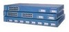
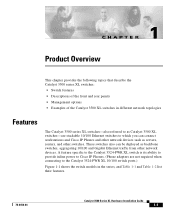
...; Examples of the Catalyst 3500 XL switches in different network topologies Features The Catalyst 3500 series XL switches-also referred to as Catalyst 3500 XL switches-are not required when connecting to which you can be deployed as servers, routers, and other network devices. A feature specific to the Catalyst 3524-PWR XL switch is its ability to provide inline power to Cisco IP Phones...
...; Examples of the Catalyst 3500 XL switches in different network topologies Features The Catalyst 3500 series XL switches-also referred to as Catalyst 3500 XL switches-are not required when connecting to which you can be deployed as servers, routers, and other network devices. A feature specific to the Catalyst 3524-PWR XL switch is its ability to provide inline power to Cisco IP Phones...
Installation Guide
Page 32
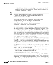
...for inline power on a port, the port Catalyst 3500 Series XL Hardware Installation Guide 1-8 78-6456-04 When connecting the switch to operate in Appendix B, "Connector and Cable Specifications." If the connected device also supports autonegotiation, the switch port negotiates the best connection (that is, the...and duplex autonegotiation, compliant with IEEE 802.3u. Refer to the following phones: Cisco IP Phone 7960, Cisco IP Phone 7940, and Cisco IP Phone 7910 • Automatically detect if a Cisco IP Phone is connected. CMS and the CLI provide two inline power settings for...
...for inline power on a port, the port Catalyst 3500 Series XL Hardware Installation Guide 1-8 78-6456-04 When connecting the switch to operate in Appendix B, "Connector and Cable Specifications." If the connected device also supports autonegotiation, the switch port negotiates the best connection (that is, the...and duplex autonegotiation, compliant with IEEE 802.3u. Refer to the following phones: Cisco IP Phone 7960, Cisco IP Phone 7940, and Cisco IP Phone 7910 • Automatically detect if a Cisco IP Phone is connected. CMS and the CLI provide two inline power settings for...
Installation Guide
Page 47
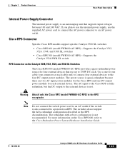
...-with-reboot configuration is not. Cisco RPS Connector Specific Cisco RPS models support specific Catalyst 3500 XL switches: • Cisco RPS 600 (model PWR600-AC-RPS)-Supports the Catalyst 3512, 3524, 3548, and 3508 XL switches • Cisco RPS 300 (model PWR300-AC-RPS)-Supports the Catalyst 3524-PWR XL switch RPS Connector on the Catalyst 3508, 3512, 3524, and 3548 XL Switches The Cisco RPS 600 (model PWR600...
...-with-reboot configuration is not. Cisco RPS Connector Specific Cisco RPS models support specific Catalyst 3500 XL switches: • Cisco RPS 600 (model PWR600-AC-RPS)-Supports the Catalyst 3512, 3524, 3548, and 3508 XL switches • Cisco RPS 300 (model PWR300-AC-RPS)-Supports the Catalyst 3524-PWR XL switch RPS Connector on the Catalyst 3508, 3512, 3524, and 3548 XL Switches The Cisco RPS 600 (model PWR600...
Installation Guide
Page 48
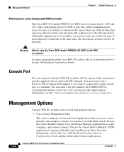
... pinout information, see the "Cable and Adapter Specifications" section on the Cisco RPS 300, refer to manage individual and standalone switches. It automatically senses when one switch fails at a time. You can connect a Catalyst 3500 XL switch to create, configure, and monitor clusters. Although...a fully-redundant power source for these applications. 1-24 Catalyst 3500 Series XL Hardware Installation Guide 78-6456-04 Management Options Chapter 1 Product Overview RPS Connector on the Catalyst 3524-PWR XL Switch The Cisco RPS 300 (model PWR300-AC-RPS) has two output ...
... pinout information, see the "Cable and Adapter Specifications" section on the Cisco RPS 300, refer to manage individual and standalone switches. It automatically senses when one switch fails at a time. You can connect a Catalyst 3500 XL switch to create, configure, and monitor clusters. Although...a fully-redundant power source for these applications. 1-24 Catalyst 3500 Series XL Hardware Installation Guide 78-6456-04 Management Options Chapter 1 Product Overview RPS Connector on the Catalyst 3524-PWR XL Switch The Cisco RPS 300 (model PWR300-AC-RPS) has two output ...

Installation Guide
Page 65
... A equipment is designed for typical commercial establishments for Installation Warning This equipment is within the ranges listed in Appendix A, "Technical Specifications." 78-6456-04 Catalyst 3500 Series XL Hardware Installation Guide 2-7 Statement 256 Installation Guidelines When determining where to place the switch, be used and installed properly according to the connected devices are used.
... A equipment is designed for typical commercial establishments for Installation Warning This equipment is within the ranges listed in Appendix A, "Technical Specifications." 78-6456-04 Catalyst 3500 Series XL Hardware Installation Guide 2-7 Statement 256 Installation Guidelines When determining where to place the switch, be used and installed properly according to the connected devices are used.

Installation Guide
Page 81
... baud rate. For console port and adapter pinout information, see the "Cable and Adapter Specifications" section on the GigaStack GBIC connections and configuration scenarios, see the Catalyst GigaStack Gigabit Interface Converter Hardware Installation Guide. You need to provide a RJ-45-to...PC application such as Hyperterminal or Procomm Plus-makes communication between the switch and your PC- See the Cisco IOS Desktop Switching Software Configuration Guide for instructions. 78-6456-04 Catalyst 3500 Series XL Hardware Installation Guide 2-23 Configure the baud rate and character format...
... baud rate. For console port and adapter pinout information, see the "Cable and Adapter Specifications" section on the GigaStack GBIC connections and configuration scenarios, see the Catalyst GigaStack Gigabit Interface Converter Hardware Installation Guide. You need to provide a RJ-45-to...PC application such as Hyperterminal or Procomm Plus-makes communication between the switch and your PC- See the Cisco IOS Desktop Switching Software Configuration Guide for instructions. 78-6456-04 Catalyst 3500 Series XL Hardware Installation Guide 2-23 Configure the baud rate and character format...

Installation Guide
Page 84
... DTE adapter if you like to the switch console port. For console port and adapter pinout information, see the "Cable and Adapter Specifications" section on page B-4. Assigning Switch Information Chapter 2 Installing and Starting Up the Switch Default gateway (router Enable secret password Use... ACS-DSBUASYN=) containing that adapter from Cisco. The data characteristics are 9600 baud, 8 data bits, 1 stop bit, and no ]: y If this procedure to create an initial configuration for the switch, and press Return: 2-26 Catalyst 3500 Series XL Hardware Installation Guide 78-6456-04
... DTE adapter if you like to the switch console port. For console port and adapter pinout information, see the "Cable and Adapter Specifications" section on page B-4. Assigning Switch Information Chapter 2 Installing and Starting Up the Switch Default gateway (router Enable secret password Use... ACS-DSBUASYN=) containing that adapter from Cisco. The data characteristics are 9600 baud, 8 data bits, 1 stop bit, and no ]: y If this procedure to create an initial configuration for the switch, and press Return: 2-26 Catalyst 3500 Series XL Hardware Installation Guide 78-6456-04

Installation Guide
Page 97
Table A-4 lists the regulatory agency approvals. A A P P E N D I X Technical Specifications 78-6456-04 Table A-1, Table A-2, and Table A-3, list the technical specifications for the Catalyst 3508G XL Switch Environmental Ranges Operating temperature Storage temperature Operating humidity Operating altitude Storage altitude Power Requirements AC input voltage DC ...3A 82.2W 280 Btus per hour 12 lb (5.45 kg) 1.75 x 16 x 17.5 in. (4.45 x 40.46 x 44.45 cm) Catalyst 3500 Series XL Hardware Installation Guide A-1 Table A-1 Technical Specifications for the Catalyst 3500 series XL switches.
Table A-4 lists the regulatory agency approvals. A A P P E N D I X Technical Specifications 78-6456-04 Table A-1, Table A-2, and Table A-3, list the technical specifications for the Catalyst 3508G XL Switch Environmental Ranges Operating temperature Storage temperature Operating humidity Operating altitude Storage altitude Power Requirements AC input voltage DC ...3A 82.2W 280 Btus per hour 12 lb (5.45 kg) 1.75 x 16 x 17.5 in. (4.45 x 40.46 x 44.45 cm) Catalyst 3500 Series XL Hardware Installation Guide A-1 Table A-1 Technical Specifications for the Catalyst 3500 series XL switches.
Installation Guide
Page 98
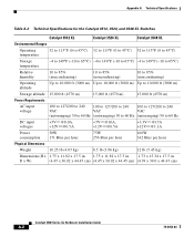
Appendix A Technical Specifications Table A-2 Technical Specifications for the Catalyst 3512, 3524, and 3548 XL Switches Catalyst 3512 XL Catalyst 3524 XL Catalyst 3548 XL Environmental Ranges Operating temperature 32 to 113°F (0 to 45°C) 32 to 113°F (0 to 45°C) 32 to 113°F (0 to 45°C) ....82 x 17.5 in. 1.73 x 15.34 x 17.5 in D x W) (4.45 x 30.02 x 44.45 cm) (4.45 x 30.02 x 44.45 cm) (4.39 x 39.0 x 44.45 cm) Catalyst 3500 Series XL Hardware Installation Guide A-2 78-6456-04
Appendix A Technical Specifications Table A-2 Technical Specifications for the Catalyst 3512, 3524, and 3548 XL Switches Catalyst 3512 XL Catalyst 3524 XL Catalyst 3548 XL Environmental Ranges Operating temperature 32 to 113°F (0 to 45°C) 32 to 113°F (0 to 45°C) 32 to 113°F (0 to 45°C) ....82 x 17.5 in. 1.73 x 15.34 x 17.5 in D x W) (4.45 x 30.02 x 44.45 cm) (4.45 x 30.02 x 44.45 cm) (4.39 x 39.0 x 44.45 cm) Catalyst 3500 Series XL Hardware Installation Guide A-2 78-6456-04

Installation Guide
Page 99
Table A-4 Catalyst 3500 Series XL Agency Approvals Safety EMC UL to UL 1950, Third Edition FCC Part 15 Class A c-UL to CAN/CSA 22.2 No. 950-95, Third Edition EN 55022 Class A (CISPR 22 Class A) TUV/GS to EN 60950 with Amendment A1-A4 and A11 ...The actual power consumption depends on the number of IP phones connected. 325W represents 24 IP phones connected. Appendix A Technical Specifications Table A-3 Technical Specifications for the Catalyst 3524-PWR XL Switch Environmental Ranges Operating temperature 32 to 113°F (0 to 45°C) Storage temperature -4 to 149°F (-10 ...
Table A-4 Catalyst 3500 Series XL Agency Approvals Safety EMC UL to UL 1950, Third Edition FCC Part 15 Class A c-UL to CAN/CSA 22.2 No. 950-95, Third Edition EN 55022 Class A (CISPR 22 Class A) TUV/GS to EN 60950 with Amendment A1-A4 and A11 ...The actual power consumption depends on the number of IP phones connected. 325W represents 24 IP phones connected. Appendix A Technical Specifications Table A-3 Technical Specifications for the Catalyst 3524-PWR XL Switch Environmental Ranges Operating temperature 32 to 113°F (0 to 45°C) Storage temperature -4 to 149°F (-10 ...

Installation Guide
Page 100
Appendix A Technical Specifications Catalyst 3500 Series XL Hardware Installation Guide A-4 78-6456-04
Appendix A Technical Specifications Catalyst 3500 Series XL Hardware Installation Guide A-4 78-6456-04
Installation Guide
Page 101
...two ports when one of the ports is designated with an X or when both ports are designated with an X. Connector Specifications 10/100 Ports The 10/100 Ethernet ports use standard RJ-45 connectors and Ethernet pinouts with internal crossovers, as indicated... have an X. 78-6456-04 Catalyst 3500 Series XL Hardware Installation Guide B-1 APPENDIX B Connector and Cable Specifications This appendix describes the Catalyst 3500 XL switch ports and the cables and adapters that you use to connect the switch to compatible workstations, servers, routers, and Cisco IP Phones, you use a crossover...
...two ports when one of the ports is designated with an X or when both ports are designated with an X. Connector Specifications 10/100 Ports The 10/100 Ethernet ports use standard RJ-45 connectors and Ethernet pinouts with internal crossovers, as indicated... have an X. 78-6456-04 Catalyst 3500 Series XL Hardware Installation Guide B-1 APPENDIX B Connector and Cable Specifications This appendix describes the Catalyst 3500 XL switch ports and the cables and adapters that you use to connect the switch to compatible workstations, servers, routers, and Cisco IP Phones, you use a crossover...

Installation Guide
Page 102
Figure B-2 1000BaseX SC Connector H8707 Tx Rx Catalyst 3500 Series XL Hardware Installation Guide B-2 78-6456-04 Connector Specifications Appendix B Connector and Cable Specifications Figure B-1 10/100 Port Pinouts Pin Label 1 RD+ 2 RD- 3 TD+ 4 NC 5 NC 6 TD- 7 NC 8 NC 12345678 H5318 1000BaseX Ports 1000BaseX ports use duplex SC connectors, as shown in Figure B-2.
Figure B-2 1000BaseX SC Connector H8707 Tx Rx Catalyst 3500 Series XL Hardware Installation Guide B-2 78-6456-04 Connector Specifications Appendix B Connector and Cable Specifications Figure B-1 10/100 Port Pinouts Pin Label 1 RD+ 2 RD- 3 TD+ 4 NC 5 NC 6 TD- 7 NC 8 NC 12345678 H5318 1000BaseX Ports 1000BaseX ports use duplex SC connectors, as shown in Figure B-2.

Installation Guide
Page 103
... information, see Table B-1 and Table B-2. 78-6456-04 Catalyst 3500 Series XL Hardware Installation Guide B-3 Figure B-3 GigaStack Connector 22084 The GigaStack GBIC cables are used to connect the console port of the switch to a terminal. Caution Do not use standard IEEE 1394 ...25 female DTE adapter if you want to connect the switch console port to a console PC. You can order a kit (part number ACS-DSBUASYN=) containing that adapter from Cisco. Appendix B Connector and Cable Specifications Connector Specifications Gigastack Port The GigaStack Gigabit Interface Converter (GBIC) uses ...
... information, see Table B-1 and Table B-2. 78-6456-04 Catalyst 3500 Series XL Hardware Installation Guide B-3 Figure B-3 GigaStack Connector 22084 The GigaStack GBIC cables are used to connect the console port of the switch to a terminal. Caution Do not use standard IEEE 1394 ...25 female DTE adapter if you want to connect the switch console port to a console PC. You can order a kit (part number ACS-DSBUASYN=) containing that adapter from Cisco. Appendix B Connector and Cable Specifications Connector Specifications Gigastack Port The GigaStack Gigabit Interface Converter (GBIC) uses ...

Installation Guide
Page 104
Figure B-4 Crossover Cable Schematic Switch 3 TD+ 6 TD- H5578 Catalyst 3500 Series XL Hardware Installation Guide B-4 78-6456-04 H5579 Figure B-5 Straight-Through Cable Schematic Switch 3 TD+ 6 TD- Switch 3 RD+ 6 RD- 1 RD+ 2 RD- 1 TD+ 2 TD- Switch 3 TD+ 6 TD- 1 RD+ 2 RD- 1 RD+ 2 RD- Cable and Adapter Specifications Appendix B Connector and Cable Specifications Cable and Adapter Specifications Crossover and Straight-Through Cable Pinouts The schematics of crossover and straight-through cables are shown in Figure B-4 and Figure B-5.
Figure B-4 Crossover Cable Schematic Switch 3 TD+ 6 TD- H5578 Catalyst 3500 Series XL Hardware Installation Guide B-4 78-6456-04 H5579 Figure B-5 Straight-Through Cable Schematic Switch 3 TD+ 6 TD- Switch 3 RD+ 6 RD- 1 RD+ 2 RD- 1 TD+ 2 TD- Switch 3 TD+ 6 TD- 1 RD+ 2 RD- 1 RD+ 2 RD- Cable and Adapter Specifications Appendix B Connector and Cable Specifications Cable and Adapter Specifications Crossover and Straight-Through Cable Pinouts The schematics of crossover and straight-through cables are shown in Figure B-4 and Figure B-5.

Installation Guide
Page 105
... the other connector should be the same color. Pin 8 H10632 78-6456-04 Catalyst 3500 Series XL Hardware Installation Guide B-5 Hold the cable ends side-by-side, with the tab at the back. Appendix B Connector and Cable Specifications Cable and Adapter Specifications Rollover Cable and Adapter Pinouts Identifying a Rollover Cable To identify a rollover cable...
... the other connector should be the same color. Pin 8 H10632 78-6456-04 Catalyst 3500 Series XL Hardware Installation Guide B-5 Hold the cable ends side-by-side, with the tab at the back. Appendix B Connector and Cable Specifications Cable and Adapter Specifications Rollover Cable and Adapter Pinouts Identifying a Rollover Cable To identify a rollover cable...

Installation Guide
Page 106
... 5 5 3 4 7 Console Device Signal CTS DSR RxD GND GND TxD DTR RTS Catalyst 3500 Series XL Hardware Installation Guide B-6 78-6456-04 Figure B-7 Connecting the Console Port to a PC PC Catalyst 3500 series XL switch 22003 RJ-45-to-RJ-45 rollover cable RJ-45-to-DB-9 adapter (labeled TERMINAL...3 6 GND 4 5 GND 5 4 RxD 6 3 Not connected 7 2 CTS 8 1 RJ-45-to -DB-9 female DTE adapter. Cable and Adapter Specifications Appendix B Connector and Cable Specifications Connecting to a PC Use the supplied thin, flat, RJ-45-to-RJ-45 rollover cable and RJ-45-to-DB-9 female DTE adapter...
... 5 5 3 4 7 Console Device Signal CTS DSR RxD GND GND TxD DTR RTS Catalyst 3500 Series XL Hardware Installation Guide B-6 78-6456-04 Figure B-7 Connecting the Console Port to a PC PC Catalyst 3500 series XL switch 22003 RJ-45-to-RJ-45 rollover cable RJ-45-to-DB-9 adapter (labeled TERMINAL...3 6 GND 4 5 GND 5 4 RxD 6 3 Not connected 7 2 CTS 8 1 RJ-45-to -DB-9 female DTE adapter. Cable and Adapter Specifications Appendix B Connector and Cable Specifications Connecting to a PC Use the supplied thin, flat, RJ-45-to-RJ-45 rollover cable and RJ-45-to-DB-9 female DTE adapter...