
Hardware Installation Guide
Page 2
... into an outlet that is an adaptation of its affiliates in accordance with the instruction manual, may be required to provide reasonable protection against such interference in a commercial environment. Catalyst 3560 Switch Hardware Installation Guide © 2004-2010 Cisco Systems, Inc. IF YOU ARE UNABLE TO LOCATE THE SOFTWARE LICENSE OR LIMITED WARRANTY, CONTACT YOUR CISCO REPRESENTATIVE FOR A COPY. This equipment...
... into an outlet that is an adaptation of its affiliates in accordance with the instruction manual, may be required to provide reasonable protection against such interference in a commercial environment. Catalyst 3560 Switch Hardware Installation Guide © 2004-2010 Cisco Systems, Inc. IF YOU ARE UNABLE TO LOCATE THE SOFTWARE LICENSE OR LIMITED WARRANTY, CONTACT YOUR CISCO REPRESENTATIVE FOR A COPY. This equipment...

Hardware Installation Guide
Page 11
... deploy the switch. Product Overview 1 C H A P T E R The Catalyst 3560 switch-also referred to as the switch-is an Ethernet switch to initially configure your switch using the command-line interface (CLI), see Appendix D, "Configuring the Switch with the CLI-Based Setup Program." The Catalyst 3560-8PC and the Catalyst 3560-12PC-S compact switches provide the same Power over Ethernet (PoE) connectivity and can connect devices like workstations, Cisco Wireless Access Points, Cisco IP Phones, and other network devices such as servers, routers, and other network devices. This...
... deploy the switch. Product Overview 1 C H A P T E R The Catalyst 3560 switch-also referred to as the switch-is an Ethernet switch to initially configure your switch using the command-line interface (CLI), see Appendix D, "Configuring the Switch with the CLI-Based Setup Program." The Catalyst 3560-8PC and the Catalyst 3560-12PC-S compact switches provide the same Power over Ethernet (PoE) connectivity and can connect devices like workstations, Cisco Wireless Access Points, Cisco IP Phones, and other network devices such as servers, routers, and other network devices. This...

Hardware Installation Guide
Page 18
... cannot configure half-duplex mode on Gigabit Ethernet interfaces if the interface speed is 1000 Mb/s. • When set for speed and duplex autonegotiation, in compliance with IEEE 802.3ab. (The default setting is autonegotiate.) • You can set to operate in pairs. If the connected device also supports autonegotiation, the switch port negotiates the best connection (the fastest line speed that present a shock hazard may exist on Power over Ethernet (PoE) circuits...
... cannot configure half-duplex mode on Gigabit Ethernet interfaces if the interface speed is 1000 Mb/s. • When set for speed and duplex autonegotiation, in compliance with IEEE 802.3ab. (The default setting is autonegotiate.) • You can set to operate in pairs. If the connected device also supports autonegotiation, the switch port negotiates the best connection (the fastest line speed that present a shock hazard may exist on Power over Ethernet (PoE) circuits...

Hardware Installation Guide
Page 19
... use the mdix auto interface configuration command to enable the automatic medium-dependent interface crossover (auto-MDIX) feature. The auto-MDIX feature is disabled by default on the other end of PoE. For information about configuring and monitoring PoE ports, see the documentation that came with IEEE 802.3af and Cisco prestandard PoE support for Cisco IP Phones and Cisco Aironet Access Points. • Each of the Catalyst 3560-8PC, 3560-12PC-S, 3560-24PS, and 3560V2-24PS switch...
... use the mdix auto interface configuration command to enable the automatic medium-dependent interface crossover (auto-MDIX) feature. The auto-MDIX feature is disabled by default on the other end of PoE. For information about configuring and monitoring PoE ports, see the documentation that came with IEEE 802.3af and Cisco prestandard PoE support for Cisco IP Phones and Cisco Aironet Access Points. • Each of the Catalyst 3560-8PC, 3560-12PC-S, 3560-24PS, and 3560V2-24PS switch...
Hardware Installation Guide
Page 20
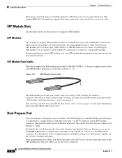
... port or as a single interface with SFP module connectors at a time. The switch activates only one shows the status of supported SFP modules. SFP Module Slots See the release notes for the active connector. 1-10 Catalyst 3560 Switch Hardware Installation Guide OL-6337-07 Use fiber-optic cables with RJ-45 connectors to connect to a fiber-optic SFP module. Front Panel Description Chapter 1 Product Overview Many legacy powered devices, including older Cisco IP phones and access points that first links up. Each port...
... port or as a single interface with SFP module connectors at a time. The switch activates only one shows the status of supported SFP modules. SFP Module Slots See the release notes for the active connector. 1-10 Catalyst 3560 Switch Hardware Installation Guide OL-6337-07 Use fiber-optic cables with RJ-45 connectors to connect to a fiber-optic SFP module. Front Panel Description Chapter 1 Product Overview Many legacy powered devices, including older Cisco IP phones and access points that first links up. Each port...

Hardware Installation Guide
Page 31
... and four Remote Monitoring (RMON) groups. For setup instructions that use to set of network configurations that use the CLI, go to Appendix D, "Configuring the Switch with your management station directly to create dedicated network segments that you purchase separately, can fully configure and monitor the switch and switch cluster members from the CLI. See the switch software configuration guide on Cisco.com for an explanation of a Simple Network Management Protocol (SNMP) platform. See the Catalyst 3560 Switch Command Reference on Cisco IOS software and...
... and four Remote Monitoring (RMON) groups. For setup instructions that use to set of network configurations that use the CLI, go to Appendix D, "Configuring the Switch with your management station directly to create dedicated network segments that you purchase separately, can fully configure and monitor the switch and switch cluster members from the CLI. See the switch software configuration guide on Cisco.com for an explanation of a Simple Network Management Protocol (SNMP) platform. See the Catalyst 3560 Switch Command Reference on Cisco IOS software and...

Hardware Installation Guide
Page 34
... wall-mounting instructions carefully before beginning installation. Statement 48 Warning An exposed wire lead from the terminal block plug. Statement 156 Warning Ethernet cables must be shielded when used in an area that is not connected to the terminals. and 48-Port Switches) Warnings These warnings are in the Regulatory Compliance and Safety Information for Installation Chapter 2 Switch Installation (24- Statement 378 Catalyst 3560 Switch Hardware Installation Guide...
... wall-mounting instructions carefully before beginning installation. Statement 48 Warning An exposed wire lead from the terminal block plug. Statement 156 Warning Ethernet cables must be shielded when used in an area that is not connected to the terminals. and 48-Port Switches) Warnings These warnings are in the Regulatory Compliance and Safety Information for Installation Chapter 2 Switch Installation (24- Statement 378 Catalyst 3560 Switch Hardware Installation Guide...
Hardware Installation Guide
Page 36
... unit. All connections must be familiar with standard practices for Installation Chapter 2 Switch Installation (24- Before you are in a situation that suitable grounding is installed, the following ports must comply with integral circuit protection: 10/100/1000 Ethernet. A restricted access area can be accessed only through an approved network termination unit with local and national electrical codes. Statement 1074 Catalyst 3560 Switch Hardware Installation Guide 2-4 OL...
... unit. All connections must be familiar with standard practices for Installation Chapter 2 Switch Installation (24- Before you are in a situation that suitable grounding is installed, the following ports must comply with integral circuit protection: 10/100/1000 Ethernet. A restricted access area can be accessed only through an approved network termination unit with local and national electrical codes. Statement 1074 Catalyst 3560 Switch Hardware Installation Guide 2-4 OL...
Hardware Installation Guide
Page 38
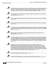
... for support. To power on the switch, connect one SFP module slot) Box Contents The switch getting started guide on the switch, and connect the other particles, causing contaminant buildup inside the chassis, which can result in an environment as free as possible from construction activities). Statement 370 Catalyst 3560 Switch Hardware Installation Guide 2-6 OL-6337-07 and 48-Port Switches) When the fiber-optic cable span is missing or damaged, contact your configuration...
... for support. To power on the switch, connect one SFP module slot) Box Contents The switch getting started guide on the switch, and connect the other particles, causing contaminant buildup inside the chassis, which can result in an environment as free as possible from construction activities). Statement 370 Catalyst 3560 Switch Hardware Installation Guide 2-6 OL-6337-07 and 48-Port Switches) When the fiber-optic cable span is missing or damaged, contact your configuration...

Hardware Installation Guide
Page 51
... security. When the auto-MDIX feature is enabled, the switch detects the required cable type for this feature, see the switch software configuration guide or the switch command reference. Therefore, you can reduce performance or result in the CLI to 10 or 100 Mb/s. Chapter 2 Switch Installation (24- Connecting devices that causes a PoE fault from the network. Only standard-compliant cabling can use either to automatically provide PoE if a Cisco IP Phone, Cisco Aironet Access Point, or end device...
... security. When the auto-MDIX feature is enabled, the switch detects the required cable type for this feature, see the switch software configuration guide or the switch command reference. Therefore, you can reduce performance or result in the CLI to 10 or 100 Mb/s. Chapter 2 Switch Installation (24- Connecting devices that causes a PoE fault from the network. Only standard-compliant cabling can use either to automatically provide PoE if a Cisco IP Phone, Cisco Aironet Access Point, or end device...

Hardware Installation Guide
Page 58
... to power lines, remove jewelry (including rings, necklaces, and watches). Do not operate the system unless all cards and faceplates are translated into several languages in a central office environment. Statement 156 Warning Ethernet cables must be shielded when used in the Regulatory Compliance and Safety Information for Installation Chapter 3 Switch Installation (8- Statement 265 Warning Attach only the following Cisco RPS model to...
... to power lines, remove jewelry (including rings, necklaces, and watches). Do not operate the system unless all cards and faceplates are translated into several languages in a central office environment. Statement 156 Warning Ethernet cables must be shielded when used in the Regulatory Compliance and Safety Information for Installation Chapter 3 Switch Installation (8- Statement 265 Warning Attach only the following Cisco RPS model to...
Hardware Installation Guide
Page 72
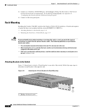
... Catalyst 3560 Switch Getting Started Guide for Rack-Mounting SYST STAT DPLX SPD PoE MODE CONSOLE 1x 2x 3x 4x 5x 6x 7x 8x Catalyst 3560 SERIES PoE-8 1 1 1 Phillips flat-head screws 3-16 Catalyst 3560 Switch Hardware Installation Guide OL-6337-07 Rack-Mounting Installing the Catalyst 3560-8PC switch or the Catalyst 3560 12-PC-S switch in a 19-inch rack requires a bracket kit that is provided with stabilizing devices, install the stabilizers before mounting or servicing the unit in the rack...
... Catalyst 3560 Switch Getting Started Guide for Rack-Mounting SYST STAT DPLX SPD PoE MODE CONSOLE 1x 2x 3x 4x 5x 6x 7x 8x Catalyst 3560 SERIES PoE-8 1 1 1 Phillips flat-head screws 3-16 Catalyst 3560 Switch Hardware Installation Guide OL-6337-07 Rack-Mounting Installing the Catalyst 3560-8PC switch or the Catalyst 3560 12-PC-S switch in a 19-inch rack requires a bracket kit that is provided with stabilizing devices, install the stabilizers before mounting or servicing the unit in the rack...
Hardware Installation Guide
Page 77
... Network Management Protocol (SNMP) workstation. You can also get statistics from the browser interface, from the command-line interface (CLI), or from an SNMP workstation. See the software configuration guide, the switch command reference guide on Cisco.com or the documentation that came with your SNMP application for more information. • Evaluate Switch POST Results, page 4-2 • Monitor Switch LEDs, page 4-2 • Verify Switch Connections, page 4-2 • Monitor Switch Performance, page 4-4 OL-6337-07 Catalyst 3560 Switch Hardware Installation Guide 4-1 This...
... Network Management Protocol (SNMP) workstation. You can also get statistics from the browser interface, from the command-line interface (CLI), or from an SNMP workstation. See the software configuration guide, the switch command reference guide on Cisco.com or the documentation that came with your SNMP application for more information. • Evaluate Switch POST Results, page 4-2 • Monitor Switch LEDs, page 4-2 • Verify Switch Connections, page 4-2 • Monitor Switch Performance, page 4-4 OL-6337-07 Catalyst 3560 Switch Hardware Installation Guide 4-1 This...

Hardware Installation Guide
Page 79
... reverse. Enable auto-MDIX on the switch. A link LED does not guarantee that the cable is not. See the "Features" section on the connected device match and that they use Category 3 copper cable for loose connections. Chapter 4 Troubleshooting Diagnosing Problems Ethernet and Fiber Cables Make sure that you have the correct cable type for the connection: • For Ethernet, use the same type of encoding, optical frequency, and fiber type. Link Status Verify that this module supports this...
... reverse. Enable auto-MDIX on the switch. A link LED does not guarantee that the cable is not. See the "Features" section on the connected device match and that they use Category 3 copper cable for loose connections. Chapter 4 Troubleshooting Diagnosing Problems Ethernet and Fiber Cables Make sure that you have the correct cable type for the connection: • For Ethernet, use the same type of encoding, optical frequency, and fiber type. Link Status Verify that this module supports this...

Hardware Installation Guide
Page 80
... server. In normal mode, UDLD detects unidirectional links because of operation (the default) and an aggressive mode. Monitor Switch Performance Review these sections when you troubleshoot switch performance problems: • Speed, Duplex, and Autonegotiation, page 4-4 • Autonegotiation and Network Interface Cards, page 4-5 • Cabling Distance, page 4-5 Speed, Duplex, and Autonegotiation If the port statistics show interfaces privileged EXEC command to be the problem. This can identify the end device MAC address in the software configuration guide. Ping...
... server. In normal mode, UDLD detects unidirectional links because of operation (the default) and an aggressive mode. Monitor Switch Performance Review these sections when you troubleshoot switch performance problems: • Speed, Duplex, and Autonegotiation, page 4-4 • Autonegotiation and Network Interface Cards, page 4-5 • Cabling Distance, page 4-5 Speed, Duplex, and Autonegotiation If the port statistics show interfaces privileged EXEC command to be the problem. This can identify the end device MAC address in the software configuration guide. Ping...

Hardware Installation Guide
Page 81
... the connected port is set both ends of the connection. • If a remote device does not autonegotiate, configure the duplex settings on the two ports to match. Chapter 4 Troubleshooting Clearing the Switch IP Address and Configuration These circumstances can result in a mismatch: • A manually set speed or duplex parameter is different from the manufacturer. By default, the switch ports and interfaces are set to configure the switch. 2. It is common for cabling guidelines. The switch LEDs begin blinking...
... the connected port is set both ends of the connection. • If a remote device does not autonegotiate, configure the duplex settings on the two ports to match. Chapter 4 Troubleshooting Clearing the Switch IP Address and Configuration These circumstances can result in a mismatch: • A manually set speed or duplex parameter is different from the manufacturer. By default, the switch ports and interfaces are set to configure the switch. 2. It is common for cabling guidelines. The switch LEDs begin blinking...
Hardware Installation Guide
Page 111
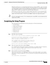
...: • Switch IP address • Subnet mask (IP netmask) • Default gateway (router) • Enable secret password • Enable password • Telnet password Step 1 Enter Yes at any point you to abort configuration dialog at these two prompts. Use ctrl-c to configure each interface on . Basic management setup configures only enough connectivity for any switch. Completing the Setup Program The setup program runs automatically after the switch powers on the system. Appendix D Configuring the Switch with a number, is...
...: • Switch IP address • Subnet mask (IP netmask) • Default gateway (router) • Enable secret password • Enable password • Telnet password Step 1 Enter Yes at any point you to abort configuration dialog at these two prompts. Use ctrl-c to configure each interface on . Basic management setup configures only enough connectivity for any switch. Completing the Setup Program The setup program runs automatically after the switch powers on the system. Appendix D Configuring the Switch with a number, is...

Hardware Installation Guide
Page 113
... (SFP) modules, see the Getting Started with the CLI-Based Setup Program Completing the Setup Program ! and 12-Port Switches)." If you want to change this configuration to save the configuration and use the CLI, enter commands at the Switch> prompt through the console port by using a terminal emulation program or through the network by selecting option 2. To use CMS, see the switch software configuration guide or the switch command reference. OL-6337-07 Catalyst 3560 Switch Hardware Installation Guide D-5 and 48-Port Switches)" and...
... (SFP) modules, see the Getting Started with the CLI-Based Setup Program Completing the Setup Program ! and 12-Port Switches)." If you want to change this configuration to save the configuration and use the CLI, enter commands at the Switch> prompt through the console port by using a terminal emulation program or through the network by selecting option 2. To use CMS, see the switch software configuration guide or the switch command reference. OL-6337-07 Catalyst 3560 Switch Hardware Installation Guide D-5 and 48-Port Switches)" and...

Hardware Installation Guide
Page 116
...-mounting 24- Index torquing recommendation C-6 Cisco IOS command-line interface 1-21 Cisco IP Phones, connecting to 1-9, 2-20 Cisco Network Assistant 1-20 Cisco RPS See RPS CiscoView 1-21 CLI to manage switch 1-21 to set up switch D-1 code compliance warning 2-4, 3-4 command-line interface See CLI configuration examples, network 1-1 connecting to 10/100/1000 ports 2-19 to 10/100 ports 2-19 to console port B-3 to DC power C-1 to C-2 to SFP modules 2-21 to 2-23 connection procedures 2-19 to 2-23 connectors and cables 10/100 ports B-2 console port B-3 to B-8 dual-purpose ports B-3 power...
...-mounting 24- Index torquing recommendation C-6 Cisco IOS command-line interface 1-21 Cisco IP Phones, connecting to 1-9, 2-20 Cisco Network Assistant 1-20 Cisco RPS See RPS CiscoView 1-21 CLI to manage switch 1-21 to set up switch D-1 code compliance warning 2-4, 3-4 command-line interface See CLI configuration examples, network 1-1 connecting to 10/100/1000 ports 2-19 to 10/100 ports 2-19 to console port B-3 to DC power C-1 to C-2 to SFP modules 2-21 to 2-23 connection procedures 2-19 to 2-23 connectors and cables 10/100 ports B-2 console port B-3 to B-8 dual-purpose ports B-3 power...
Hardware Installation Guide
Page 119
... removal 2-17 cable specifications B-4 connecting to 2-21 to 2-23 connectors B-2 described 1-10 installation 2-16 to 4-6 bad or damaged cable 4-2 connection problems 4-2 diagnosing problems 4-1 Ethernet and fiber-optic cables 4-3 link status 4-3 ping end device 4-4 port and interface settings 4-4 POST 4-1 spanning tree loops 4-4 speed, duplex, and autonegotiation 4-4 switch performance 4-4 troubleshooting spanning tree loops 4-4 W wall-mounting 24- and 48-port switches) 2-2 installation (8- and 12-port switches 3-8 Simple Network Management Protocol See SNMP SNMP network management...
... removal 2-17 cable specifications B-4 connecting to 2-21 to 2-23 connectors B-2 described 1-10 installation 2-16 to 4-6 bad or damaged cable 4-2 connection problems 4-2 diagnosing problems 4-1 Ethernet and fiber-optic cables 4-3 link status 4-3 ping end device 4-4 port and interface settings 4-4 POST 4-1 spanning tree loops 4-4 speed, duplex, and autonegotiation 4-4 switch performance 4-4 troubleshooting spanning tree loops 4-4 W wall-mounting 24- and 48-port switches) 2-2 installation (8- and 12-port switches 3-8 Simple Network Management Protocol See SNMP SNMP network management...


