Cisco WS-C3560-24PS-E Support and Manuals
Get Help and Manuals for this Cisco item
View All Support Options Below
Free Cisco WS-C3560-24PS-E manuals!
Problems with Cisco WS-C3560-24PS-E?
Ask a Question
Free Cisco WS-C3560-24PS-E manuals!
Problems with Cisco WS-C3560-24PS-E?
Ask a Question
Popular Cisco WS-C3560-24PS-E Manual Pages
Hardware Installation Guide - Page 3
... System LED 1-11 RPS LED 1-12 Port LEDs and Modes 1-13 Dual-Purpose Port LEDs 1-15 Cable Guard 1-15 Rear Panel Description 1-15 Internal Power Supply 1-18 DC Power Connector 1-18 Cisco RPS 1-19 Cisco RPS 2300 1-19 Cisco RPS 675 1-19 Console Port 1-19 Security Slots 1-20 Management Options 1-20
Catalyst 3560 Switch Hardware Installation Guide
iii
Hardware Installation Guide - Page 20
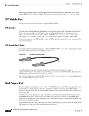
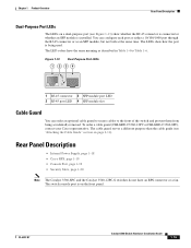
... cable with dual front ends-an RJ-45 connector and an SFP module connector. The dual front ends are field-replaceable, providing uplink interfaces when inserted in the "SFP Module Cable Specifications" section on page B-4. By default, the switch dynamically selects the interface type that do not fully support IEEE 802.3af, might not support PoE when connected to...
Hardware Installation Guide - Page 22
... Cisco.
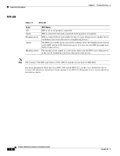
The internal power supply in a fault condition.
Press the Standby/Active button on the RPS, and the LED should turn green. For more information about the Cisco RPS 2300 and the RPS 675, see the Cisco Redundant Power System 2300 Hardware Installation Guide and the Cisco RPS 675 Redundant Power System Hardware Installation Guide.
1-12
Catalyst 3560 Switch Hardware Installation Guide...
Hardware Installation Guide - Page 25
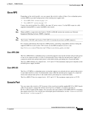
... or a fan. Rear Panel Description
• Internal Power Supply, page 1-18 • Cisco RPS, page 1-19 • Console Port, page 1-19 • Security Slots, page 1-20
Note The Catalyst 3560-8PC and the Catalyst 3560-12PC-S switches do not have the same meaning as an SFP module, but not both at the same time...
Hardware Installation Guide - Page 29
...a time.
For complete information about the Cisco RPS products, including compatibility matrixes listing the supported RPS for each Catalyst 3560 switch, see the "Connector and Cable Specifications" section on the installed power-supply modules. It automatically senses when the internal power supply of a connected switch fails and provides power to the switch.
Use the RPS connector...
Hardware Installation Guide - Page 36
... one power supply connection. All connections must comply with integral circuit protection: 10/100/1000 Ethernet. Statement 1044
Warning When installing or replacing the unit, the ground connection must be made first and disconnected last. Avoid using such interconnection methods, unless the exposed metal parts are located within a restricted access location and users and service people...
Hardware Installation Guide - Page 38
... normal operation. See Section 3, "Running Express Setup," in a rack, on a wall, or on the 1000BASE-ZX SFP module at each end of the power cord to rack-mount the switch. Set the RPS to run Express Setup.
Warning Attach only the following Cisco RPS model to all Cisco Ethernet switches except for support.
However, these fans and blowers can draw...
Hardware Installation Guide - Page 39
...-07
Catalyst 3560 Switch Hardware Installation Guide
2-7 and 48-Port Switches)
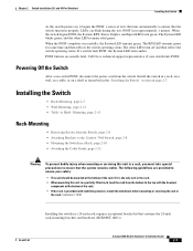
Installing the Switch
As the switch powers on page 2-7. The System LED blinks green, and the other LEDs turn green.
LEDs can blink during the test. When the POST completes successfully, the System LED remains green. Call Cisco technical support representative if your safety:
•...
Hardware Installation Guide - Page 52
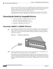
... the "Cable and Adapter Specifications" section on page B-4 for more than one RJ-45 connector. Connecting the Switch to the switch. Many legacy powered devices, including older Cisco IP phones and access points that do not fully support IEEE 802.3af, might be turned on the other end of the Cisco IP Phone might have established...
Hardware Installation Guide - Page 60

... of the equipment must be grounded. Statement 1072
Warning No user-serviceable parts inside. Statement 1074
Catalyst 3560 Switch Hardware Installation Guide
3-4
OL-6337-07 Statement 1024
Warning This unit might have more than one power supply connection. Use the statement number provided at the end of this equipment. Preparing for preventing accidents. Never defeat the ground...
Hardware Installation Guide - Page 63
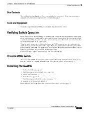
... on a shelf as described in the "Installing the Switch" section on page 3-5.
When the switch powers on the switch, connect one end of the AC power cord to an AC power outlet. If any item is missing or damaged, contact your switch fails POST. See the getting started guide for support. To power on , it passes POST. When...
Hardware Installation Guide - Page 72
...
8x
Catalyst 3560 SERIES PoE-8
1
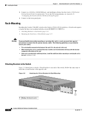
1 1 Phillips flat-head screws
3-16
Catalyst 3560 Switch Hardware Installation Guide
OL-6337-07
Figure 3-8
Attaching the 19-inch Brackets for instructions. Follow the same steps to attach the second bracket to a 10/100 or 10/100/1000 port, and run Express Setup. Installing the Switch
Chapter 3 Switch Installation (8- Connect to ensure...
Hardware Installation Guide - Page 77
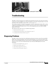
... in the power-on Cisco.com or the documentation that came with your SNMP application for more information. • Evaluate Switch POST Results, page 4-2 • Monitor Switch LEDs, page 4-2 • Verify Switch Connections, page 4-2 • Monitor Switch Performance, page 4-4
OL-6337-07
Catalyst 3560 Switch Hardware Installation Guide
4-1 Troubleshooting
4 C H A P T E R
The LEDs...
Hardware Installation Guide - Page 117
... status troubleshooting 4-3 local and national electrical codes compliance 2-4, 3-4
M
message URL http //www.cisco.com/web/learning/index.html i-vii
Mode button 1-11 mounting
desk- and 48-port switches 2-15 8- and 12-port switches 3-17
OL-6337-07
site requirements 2-5, 3-5 starting the terminal emulation software D-2 See also procedures installing SFP modules 2-16 to 2-17 internal power supply...
Hardware Installation Guide - Page 119
...autonegotiation 4-4 switch performance 4-4 troubleshooting spanning tree loops 4-4
W
wall-mounting 24- and 48-port switches) 2-2, 3-2 security slot 1-20 serial number location 4-6 servicing equipment warning C-5 SFP module patch cable
description 1-10 installing and removing 2-18 SFP modules 1000BASE-T supported speeds 1-14 bale-clasp latch removal 2-17 cable specifications B-4 connecting to 2-21...
Cisco WS-C3560-24PS-E Reviews
We have not received any reviews for Cisco yet.