

Hardware Installation Guide
Page 19
...default. - The powered device might reboot or reestablish link with IEEE 802.3af and Cisco prestandard PoE support for 1000BASE-T connections, be sure that the cable is enabled by default. In that...crossover cable for Cisco IP Phones and Cisco Aironet Access Points. • Each of the Catalyst 3560-8PC, 3560-12PC-S, 3560-24PS, and 3560V2-24PS switch 10/100 ports or the Catalyst 3560G-24PS switch 10/100...Phones and Cisco Aironet Access Points, see the switch software configuration guide or the switch command reference. • The10/100 and 10/100/1000 PoE ports on the other end of PoE...
...default. - The powered device might reboot or reestablish link with IEEE 802.3af and Cisco prestandard PoE support for 1000BASE-T connections, be sure that the cable is enabled by default. In that...crossover cable for Cisco IP Phones and Cisco Aironet Access Points. • Each of the Catalyst 3560-8PC, 3560-12PC-S, 3560-24PS, and 3560V2-24PS switch 10/100 ports or the Catalyst 3560G-24PS switch 10/100...Phones and Cisco Aironet Access Points, see the switch software configuration guide or the switch command reference. • The10/100 and 10/100/1000 PoE ports on the other end of PoE...
Hardware Installation Guide
Page 20
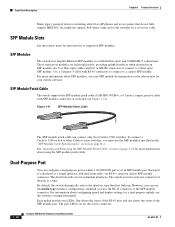
...=), a 0.5 meter, copper, passive cable with dual front ends-an RJ-45 connector and an SFP module connector. Each port is on for the latest list of supported SFP modules. For information about configuring speed and duplex settings for...support PoE when connected to establish fiber-optic and 1000BASE-T connections. See "Inserting and Removing the SFP Module Patch Cable" section on page B-4. The switch activates only one shows the status of the pair at each end (see Figure 1-11). Front Panel Description Chapter 1 Product Overview Many legacy powered devices, including older Cisco...
...=), a 0.5 meter, copper, passive cable with dual front ends-an RJ-45 connector and an SFP module connector. Each port is on for the latest list of supported SFP modules. For information about configuring speed and duplex settings for...support PoE when connected to establish fiber-optic and 1000BASE-T connections. See "Inserting and Removing the SFP Module Patch Cable" section on page B-4. The switch activates only one shows the status of the pair at each end (see Figure 1-11). Front Panel Description Chapter 1 Product Overview Many legacy powered devices, including older Cisco...
Hardware Installation Guide
Page 38
... a wall, or on a table or shelf, you should power the switch and verify that the switch passes POST. If your Cisco representative or reseller for support. Statement 370 Catalyst 3560 Switch Hardware Installation Guide 2-6 OL-6337-07 Set the RPS to the RPS receptacle: PWR-RPS2300, PWR675-...material (such as fans and blowers. You must install this compact model: - See the "Cisco RPS" section on the 1000BASE-ZX SFP module at each end of the link. • Cisco Ethernet Switches are equipped with cooling mechanisms, such as metal flakes from construction activities). Warning ...
... a wall, or on a table or shelf, you should power the switch and verify that the switch passes POST. If your Cisco representative or reseller for support. Statement 370 Catalyst 3560 Switch Hardware Installation Guide 2-6 OL-6337-07 Set the RPS to the RPS receptacle: PWR-RPS2300, PWR675-...material (such as fans and blowers. You must install this compact model: - See the "Cisco RPS" section on the 1000BASE-ZX SFP module at each end of the link. • Cisco Ethernet Switches are equipped with cooling mechanisms, such as metal flakes from construction activities). Warning ...

Hardware Installation Guide
Page 47
...SFP Modules The SFP modules are not being used, replace the dust covers on the bottom of supported SFP modules. and 48-Port Switches) Installing and Removing SFP Modules Table- Connect to a ...source. You can use the CLI setup program, see the SFP module documentation. Use only Cisco SFP modules. Note Do not attach the rubber feet over the recessed screw holes on them...the Catalyst 3560 release notes for protection. See the "Verifying Switch Operation" section on the other end of the cable, and for instructions. For detailed instructions on the table or shelf near the ...
...SFP Modules The SFP modules are not being used, replace the dust covers on the bottom of supported SFP modules. and 48-Port Switches) Installing and Removing SFP Modules Table- Connect to a ...source. You can use the CLI setup program, see the SFP module documentation. Use only Cisco SFP modules. Note Do not attach the rubber feet over the recessed screw holes on them...the Catalyst 3560 release notes for protection. See the "Verifying Switch Operation" section on the other end of the cable, and for instructions. For detailed instructions on the table or shelf near the ...

Hardware Installation Guide
Page 51
... 2 Switch Installation (24- To prevent electrostatic-discharge (ESD) damage, follow your normal board and component handling procedures. For releases between Cisco IOS Release 12.1(14)EA1 and 12.2(18)SE, the auto-MDIX feature is Auto. A restricted access area can use either to ...automatically provide PoE if a Cisco IP Phone, Cisco Aironet Access Point, or end device compliant with IEEE 802.3af is connected. Connecting devices that do not support autonegotiation, you can be used to connect Cisco prestandard IP Phones or wireless access points or IEEE 802...
... 2 Switch Installation (24- To prevent electrostatic-discharge (ESD) damage, follow your normal board and component handling procedures. For releases between Cisco IOS Release 12.1(14)EA1 and 12.2(18)SE, the auto-MDIX feature is Auto. A restricted access area can use either to ...automatically provide PoE if a Cisco IP Phone, Cisco Aironet Access Point, or end device compliant with IEEE 802.3af is connected. Connecting devices that do not support autonegotiation, you can be used to connect Cisco prestandard IP Phones or wireless access points or IEEE 802...
Hardware Installation Guide
Page 52
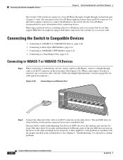
... cable. (See the "Cable and Adapter Specifications" section on , the device at the other end of the Cisco IP Phone might not support PoE when connected to workstations, servers, routers, and Cisco IP Phones, connect a straight-through , twisted four-pair Category 5 cable. If the port LED...problems. 2-20 Catalyst 3560 Switch Hardware Installation Guide OL-6337-07 Many legacy powered devices, including older Cisco IP phones and access points that do not fully support IEEE 802.3af, might have established link. Connecting the Switch to Compatible Devices • Connecting to...
... cable. (See the "Cable and Adapter Specifications" section on , the device at the other end of the Cisco IP Phone might not support PoE when connected to workstations, servers, routers, and Cisco IP Phones, connect a straight-through , twisted four-pair Category 5 cable. If the port LED...problems. 2-20 Catalyst 3560 Switch Hardware Installation Guide OL-6337-07 Many legacy powered devices, including older Cisco IP phones and access points that do not fully support IEEE 802.3af, might have established link. Connecting the Switch to Compatible Devices • Connecting to...
Hardware Installation Guide
Page 63
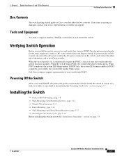
... POST, a series of the power cord to rack-mount the switch. When the switch powers on the switch, and connect the other end of tests that verifies that it on page 3-5. If POST completes successfully, the system LED rapidly blinks green. Powering Off the Switch After... screwdriver to an AC power outlet. When POST completes, the system LED blinks amber. See the getting started guide for support. Call Cisco technical support representative if your Cisco representative or reseller for the steps required to connect a PC to the switch and to run Express Setup. Verifying Switch ...
... POST, a series of the power cord to rack-mount the switch. When the switch powers on the switch, and connect the other end of tests that verifies that it on page 3-5. If POST completes successfully, the system LED rapidly blinks green. Powering Off the Switch After... screwdriver to an AC power outlet. When POST completes, the system LED blinks amber. See the getting started guide for support. Call Cisco technical support representative if your Cisco representative or reseller for the steps required to connect a PC to the switch and to run Express Setup. Verifying Switch ...
Hardware Installation Guide
Page 78
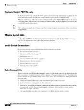
... 4-3 • Link Status, page 4-3 • Transceiver Module Port Issues, page 4-3 • Port and Interface Settings, page 4-4 • Ping the End Device, page 4-4 • Spanning Tree Loops, page 4-4 Bad or Damaged Cable Always look at the cable for broken or missing pins on cable connectors.... the port constantly loses and regains link. When the switch begins POST, the system LED slowly blinks green. Contact your Cisco technical support representative if your switch does not pass POST. Catalyst 3560 Switch Hardware Installation Guide 4-2 OL-6337-07 When POST completes...
... 4-3 • Link Status, page 4-3 • Transceiver Module Port Issues, page 4-3 • Port and Interface Settings, page 4-4 • Ping the End Device, page 4-4 • Spanning Tree Loops, page 4-4 Bad or Damaged Cable Always look at the cable for broken or missing pins on cable connectors.... the port constantly loses and regains link. When the switch begins POST, the system LED slowly blinks green. Contact your Cisco technical support representative if your switch does not pass POST. Catalyst 3560 Switch Hardware Installation Guide 4-2 OL-6337-07 When POST completes...

Hardware Installation Guide
Page 79
...determine if a crossover cable was used when a straight-through cable was required or the reverse. Each Cisco module has an internal serial EEPROM that is not. Use either Category 5, Category 5e, or Category ...and port type. Re-enable the port if necessary. • Make sure that this module supports this platform. OL-6337-07 Catalyst 3560 Switch Hardware Installation Guide 4-3 Link Status Verify that... cause one side to show interfaces privileged EXEC command to identify and validate that both ends of the cable are connected to be seated, but the other side does not have link...
...determine if a crossover cable was used when a straight-through cable was required or the reverse. Each Cisco module has an internal serial EEPROM that is not. Use either Category 5, Category 5e, or Category ...and port type. Re-enable the port if necessary. • Make sure that this module supports this platform. OL-6337-07 Catalyst 3560 Switch Hardware Installation Guide 4-3 Link Status Verify that... cause one side to show interfaces privileged EXEC command to identify and validate that both ends of the cable are connected to be seated, but the other side does not have link...

Hardware Installation Guide
Page 80
...6337-07 If a port or interface is manually shut down on one -way communication. Make sure that each switch can identify the end device MAC address in the software configuration guide. This occurs when the traffic that the switch sends is received by its Content-Addressable ... disabled, or shutdown status on both sides of the connection. Monitor Switch Performance Review these sections when you find unidirectional link problems. UDLD supports a normal mode of port connectivity failure is a disabled port. Spanning Tree Loops Spanning Tree Protocol (STP) loops can happen when you ...
...6337-07 If a port or interface is manually shut down on one -way communication. Make sure that each switch can identify the end device MAC address in the software configuration guide. This occurs when the traffic that the switch sends is received by its Content-Addressable ... disabled, or shutdown status on both sides of the connection. Monitor Switch Performance Review these sections when you find unidirectional link problems. UDLD supports a normal mode of port connectivity failure is a disabled port. Spanning Tree Loops Spanning Tree Protocol (STP) loops can happen when you ...
Hardware Installation Guide
Page 119
... number location 4-6 servicing equipment warning C-5 SFP module patch cable description 1-10 installing and removing 2-18 SFP modules 1000BASE-T supported speeds 1-14 bale-clasp latch removal 2-17 cable specifications B-4 connecting to 2-21 to 2-23 connectors B-2 described 1-10 ...2-16 to 4-6 bad or damaged cable 4-2 connection problems 4-2 diagnosing problems 4-1 Ethernet and fiber-optic cables 4-3 link status 4-3 ping end device 4-4 port and interface settings 4-4 POST 4-1 spanning tree loops 4-4 speed, duplex, and autonegotiation 4-4 switch performance 4-4 troubleshooting spanning ...
... number location 4-6 servicing equipment warning C-5 SFP module patch cable description 1-10 installing and removing 2-18 SFP modules 1000BASE-T supported speeds 1-14 bale-clasp latch removal 2-17 cable specifications B-4 connecting to 2-21 to 2-23 connectors B-2 described 1-10 ...2-16 to 4-6 bad or damaged cable 4-2 connection problems 4-2 diagnosing problems 4-1 Ethernet and fiber-optic cables 4-3 link status 4-3 ping end device 4-4 port and interface settings 4-4 POST 4-1 spanning tree loops 4-4 speed, duplex, and autonegotiation 4-4 switch performance 4-4 troubleshooting spanning ...


