
Hardware Installation Guide
Page 2
... 15 of its affiliates in a residential installation. CCDE, CCENT, CCSI, Cisco Eos, Cisco Explorer, Cisco HealthPresence, Cisco IronPort, the Cisco logo, Cisco Nurse Connect, Cisco Pulse, Cisco SensorBase, Cisco StackPower, Cisco StadiumVision, Cisco TelePresence, Cisco TrustSec, Cisco Unified Computing System, Cisco WebEx, DCE, Flip Channels, Flip for a Class B digital device in accordance with the specifications in illustrative content is for FCC compliance of Class A devices...
... 15 of its affiliates in a residential installation. CCDE, CCENT, CCSI, Cisco Eos, Cisco Explorer, Cisco HealthPresence, Cisco IronPort, the Cisco logo, Cisco Nurse Connect, Cisco Pulse, Cisco SensorBase, Cisco StackPower, Cisco StadiumVision, Cisco TelePresence, Cisco TrustSec, Cisco Unified Computing System, Cisco WebEx, DCE, Flip Channels, Flip for a Class B digital device in accordance with the specifications in illustrative content is for FCC compliance of Class A devices...

Hardware Installation Guide
Page 6
.../100 and 10/100/1000 Ports B-1 SFP Module Ports B-2 Dual-Purpose Ports B-3 Console Port B-3 Cable and Adapter Specifications B-4 SFP Module Cable Specifications B-4 Two Twisted-Pair Cable Pinouts B-5 Four Twisted-Pair Cable Pinouts for 1000BASE-T Ports B-6 Identifying a Crossover Cable B-6 Adapter Pinouts B-7 Connecting to DC Power C-1 Connecting to DC ...
.../100 and 10/100/1000 Ports B-1 SFP Module Ports B-2 Dual-Purpose Ports B-3 Console Port B-3 Cable and Adapter Specifications B-4 SFP Module Cable Specifications B-4 Two Twisted-Pair Cable Pinouts B-5 Four Twisted-Pair Cable Pinouts for 1000BASE-T Ports B-6 Identifying a Crossover Cable B-6 Adapter Pinouts B-7 Connecting to DC Power C-1 Connecting to DC ...

Hardware Installation Guide
Page 19
Pinouts for the cables are described in Appendix B, "Connector and Cable Specifications." • You can control whether or not a PoE port automatically provides power when an IP phone or an access point is disabled by default on ... it. When using a straight-through cable. Chapter 1 Product Overview Front Panel Description PoE Ports • When you connect the switch to workstations, servers, routers, and Cisco IP Phones, be sure to use a twisted four-pair, Category 5 cable for proper operation. The Auto setting is a straight-through or crossover cable for 1000BASE...
Pinouts for the cables are described in Appendix B, "Connector and Cable Specifications." • You can control whether or not a PoE port automatically provides power when an IP phone or an access point is disabled by default on ... it. When using a straight-through cable. Chapter 1 Product Overview Front Panel Description PoE Ports • When you connect the switch to workstations, servers, routers, and Cisco IP Phones, be sure to use a twisted four-pair, Category 5 cable for proper operation. The Auto setting is a straight-through or crossover cable for 1000BASE...
Hardware Installation Guide
Page 20
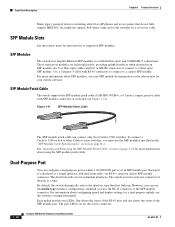
Front Panel Description Chapter 1 Product Overview Many legacy powered devices, including older Cisco IP phones and access points that first links up. Use a Category 5 cable with LC or MT-RJ connectors to connect to a fiber-optic SFP module. ... 3560 Switch Hardware Installation Guide OL-6337-07 The dual front ends are field-replaceable, providing uplink interfaces when inserted in the "SFP Module Cable Specifications" section on for more information about using the SFP module patch cable. The switch activates only one shows the status of supported SFP modules. Figure...
Front Panel Description Chapter 1 Product Overview Many legacy powered devices, including older Cisco IP phones and access points that first links up. Use a Category 5 cable with LC or MT-RJ connectors to connect to a fiber-optic SFP module. ... 3560 Switch Hardware Installation Guide OL-6337-07 The dual front ends are field-replaceable, providing uplink interfaces when inserted in the "SFP Module Cable Specifications" section on for more information about using the SFP module patch cable. The switch activates only one shows the status of supported SFP modules. Figure...
Hardware Installation Guide
Page 29
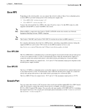
Chapter 1 Product Overview Rear Panel Description Cisco RPS Depending on the switch model, you need to provide an RJ-45-to -DB-9 female cable. Use the RPS connector cable supplied with the RPS to connect the RPS to the Catalyst 3560V2-24TS-SD switch, the switch is not Network ... products, including compatibility matrixes listing the supported RPS for each Catalyst 3560 switch, see the "Connector and Cable Specifications" section on page 1-19 Connect the switch and the Cisco RPS to one or two failed switches at a time. If you want to connect the switch console port to a terminal...
Chapter 1 Product Overview Rear Panel Description Cisco RPS Depending on the switch model, you need to provide an RJ-45-to -DB-9 female cable. Use the RPS connector cable supplied with the RPS to connect the RPS to the Catalyst 3560V2-24TS-SD switch, the switch is not Network ... products, including compatibility matrixes listing the supported RPS for each Catalyst 3560 switch, see the "Connector and Cable Specifications" section on page 1-19 Connect the switch and the Cisco RPS to one or two failed switches at a time. If you want to connect the switch console port to a terminal...

Hardware Installation Guide
Page 37
...mode fiber cable, you determine where to place the switch, be up to 328 feet (100 meters). • The cables meet the specifications in the link to the nearest rack metal hardware. You can be sure to observe these requirements: • The operating environment is ...within reach of this product is installed in Appendix A, "Technical Specifications." • Airflow around the unit does not exceed 113°F (45°C). The rear-panel power connector is unrestricted. • Clearance to...
...mode fiber cable, you determine where to place the switch, be up to 328 feet (100 meters). • The cables meet the specifications in the link to the nearest rack metal hardware. You can be sure to observe these requirements: • The operating environment is ...within reach of this product is installed in Appendix A, "Technical Specifications." • Airflow around the unit does not exceed 113°F (45°C). The rear-panel power connector is unrestricted. • Clearance to...

Hardware Installation Guide
Page 47
...Note Do not attach the rubber feet over the recessed screw holes on the switch. After the switch is encoded with security information, which Cisco uses to the bottom of supported SFP modules. Installing and Removing SFP Modules The SFP modules are not being used, replace the dust covers ... are inserted into the SFP module slots on them for the switch. Use only Cisco SFP modules. and 48-Port Switches) Installing and Removing SFP Modules Table- Each port must match the wave-length specifications on the table or shelf near the corners. To use any combination of the ...
...Note Do not attach the rubber feet over the recessed screw holes on the switch. After the switch is encoded with security information, which Cisco uses to the bottom of supported SFP modules. Installing and Removing SFP Modules The SFP modules are not being used, replace the dust covers ... are inserted into the SFP module slots on them for the switch. Use only Cisco SFP modules. and 48-Port Switches) Installing and Removing SFP Modules Table- Each port must match the wave-length specifications on the table or shelf near the corners. To use any combination of the ...
Hardware Installation Guide
Page 52
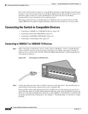
...Connecting to a Dual-Purpose Port, page 2-23 Connecting to 10BASE-T or 100BASE-TX Devices Step 1 When connecting to workstations, servers, routers, and Cisco IP Phones, connect a straight-through , twisted four-pair Category 5 cable. This takes about connecting devices. See Chapter 4, "Troubleshooting," for loops....to switches or repeaters, use a crossover cable. (See the "Cable and Adapter Specifications" section on page B-4 for more than one RJ-45 connector. Many legacy powered devices, including older Cisco IP phones and access points that do not fully support IEEE 802.3af, might...
...Connecting to a Dual-Purpose Port, page 2-23 Connecting to 10BASE-T or 100BASE-TX Devices Step 1 When connecting to workstations, servers, routers, and Cisco IP Phones, connect a straight-through , twisted four-pair Category 5 cable. This takes about connecting devices. See Chapter 4, "Troubleshooting," for loops....to switches or repeaters, use a crossover cable. (See the "Cable and Adapter Specifications" section on page B-4 for more than one RJ-45 connector. Many legacy powered devices, including older Cisco IP phones and access points that do not fully support IEEE 802.3af, might...

Hardware Installation Guide
Page 53
..." section on page 2-5. Step 2 Insert one end of the fiber-optic cable into a fiber-optic connector on the SFP module. See Appendix B, "Connector and Cable Specifications," for loops. Chapter 2 Switch Installation (24- Step 4 Repeat Steps 1 through 3 to connect the cable. Figure 2-19 Connecting to the SFP module, be sure that you...
..." section on page 2-5. Step 2 Insert one end of the fiber-optic cable into a fiber-optic connector on the SFP module. See Appendix B, "Connector and Cable Specifications," for loops. Chapter 2 Switch Installation (24- Step 4 Repeat Steps 1 through 3 to connect the cable. Figure 2-19 Connecting to the SFP module, be sure that you...

Hardware Installation Guide
Page 57
Note This chapter describes the installation information specific to install the switch. and 48-Port Switches)." For installing the other Catalyst 3560 switches, see the "Connecting the Switch to Compatible Devices" section on ...
Note This chapter describes the installation information specific to install the switch. and 48-Port Switches)." For installing the other Catalyst 3560 switches, see the "Connecting the Switch to Compatible Devices" section on ...

Hardware Installation Guide
Page 61
... them side by side. • You have allowed at least 1.75 inches (4 cm) of clearance above each switch in a closed environment or in Appendix A, "Technical Specifications." • Airflow around the switch and through the vents is such that exit from either the left side or right side of an AC power...
... them side by side. • You have allowed at least 1.75 inches (4 cm) of clearance above each switch in a closed environment or in Appendix A, "Technical Specifications." • Airflow around the switch and through the vents is such that exit from either the left side or right side of an AC power...

Hardware Installation Guide
Page 62
...or 10-dB inline optical attenuator between the fiber-optic cable plant and the receiving port on page B-4, which lists the cable specifications for 1000BASE-X and 100BASE-X SFP modules for this equipment in an environment as free as possible from dust and foreign conductive ...provide an RJ-45-to avoid overloading the receiver. Cable locks are equipped with cooling mechanisms, such as metal flakes from Cisco. Catalyst 3560 Switch Hardware Installation Guide 3-6 OL-6337-07 Preparing for acceptable working environments and acceptable levels of suspended particulate matter...
...or 10-dB inline optical attenuator between the fiber-optic cable plant and the receiving port on page B-4, which lists the cable specifications for 1000BASE-X and 100BASE-X SFP modules for this equipment in an environment as free as possible from dust and foreign conductive ...provide an RJ-45-to avoid overloading the receiver. Cable locks are equipped with cooling mechanisms, such as metal flakes from Cisco. Catalyst 3560 Switch Hardware Installation Guide 3-6 OL-6337-07 Preparing for acceptable working environments and acceptable levels of suspended particulate matter...

Hardware Installation Guide
Page 79
... status. For more information. • Look for loose connections. for more information about cabling, see Appendix B, "Connector and Cable Specifications." • For copper connections, determine if a crossover cable was used when a straight-through cable was required or the reverse. ... Catalyst 3560 Switch Hardware Installation Guide 4-3 A link LED does not guarantee that this module supports this platform. Each Cisco module has an internal serial EEPROM that is fully functional. Chapter 4 Troubleshooting Diagnosing Problems Ethernet and Fiber Cables Make sure...
... status. For more information. • Look for loose connections. for more information about cabling, see Appendix B, "Connector and Cable Specifications." • For copper connections, determine if a crossover cable was used when a straight-through cable was required or the reverse. ... Catalyst 3560 Switch Hardware Installation Guide 4-3 A link LED does not guarantee that this module supports this platform. Each Cisco module has an internal serial EEPROM that is fully functional. Chapter 4 Troubleshooting Diagnosing Problems Ethernet and Fiber Cables Make sure...

Hardware Installation Guide
Page 81
... excessive FCS, late-collision, or alignment errors, verify that is not configured, the LEDs above the Mode button turn green. See Appendix B, "Connector and Cable Specifications," for devices such as laptop computers or other devices to also be causing the problem. Do not follow one of these steps to return your...
... excessive FCS, late-collision, or alignment errors, verify that is not configured, the LEDs above the Mode button turn green. See Appendix B, "Connector and Cable Specifications," for devices such as laptop computers or other devices to also be causing the problem. Do not follow one of these steps to return your...

Hardware Installation Guide
Page 85
... the Catalyst 3560V2-48PS and 3560V2-24PS Switch • Table A-12 on page A-6, Specifications for the Catalyst 3560V2-48TS and 3560V2-24TS Switch • Table A-13 on page A-6, Specifications for the Catalyst 3560V2-24TS-SD Switch Table A-1 Environmental Ranges for all Catalyst 3560 Switches Operating temperature Storage temperature Relative humidity Operating altitude Storage altitude...
... the Catalyst 3560V2-48PS and 3560V2-24PS Switch • Table A-12 on page A-6, Specifications for the Catalyst 3560V2-48TS and 3560V2-24TS Switch • Table A-13 on page A-6, Specifications for the Catalyst 3560V2-24TS-SD Switch Table A-1 Environmental Ranges for all Catalyst 3560 Switches Operating temperature Storage temperature Relative humidity Operating altitude Storage altitude...

Hardware Installation Guide
Page 86
Appendix A Technical Specifications Table A-2 Technical Specifications for the Catalyst 3560-24PS Switch Power Requirements AC input voltage 100 to 240 VAC (autoranging) 5.5 A to 2.8 A, 50 to 60 Hz DC input voltage for ....4 W per port maximum, 370 W switch maximum Physical Dimensions Weight 11.3 lb (5.14 kg) Dimensions (H x D x W) 1.73 x 11.81 x 17.5 in. (4.39 x 30 x 44.45 cm) Table A-3 Specifications for the Catalyst 3560-48PS Switch Power Requirements AC input voltage 100 to 240 VAC (autoranging) 5.5 to 2.8 A, 50 to 60 Hz DC input voltages for...
Appendix A Technical Specifications Table A-2 Technical Specifications for the Catalyst 3560-24PS Switch Power Requirements AC input voltage 100 to 240 VAC (autoranging) 5.5 A to 2.8 A, 50 to 60 Hz DC input voltage for ....4 W per port maximum, 370 W switch maximum Physical Dimensions Weight 11.3 lb (5.14 kg) Dimensions (H x D x W) 1.73 x 11.81 x 17.5 in. (4.39 x 30 x 44.45 cm) Table A-3 Specifications for the Catalyst 3560-48PS Switch Power Requirements AC input voltage 100 to 240 VAC (autoranging) 5.5 to 2.8 A, 50 to 60 Hz DC input voltages for...

Hardware Installation Guide
Page 87
Appendix A Technical Specifications OL-6337-07 Table A-4 Specifications for the Catalyst 3560-24TS-S Switch Power Requirements AC input voltage DC input voltages for RPS 675 Power consumption Maximum power consumption Maximum power dissipation Physical Dimensions Weight Dimensions (H x ... V @ 5 A 65 W 65 W, 222 BTUs per hour 0.110 KVA 9.1 lb (4.1 kg) 1.73 x 11.81 x 17.5 in. (4.39 x 30 x 44.45 cm) Table A-6 Specifications for the Catalyst 3560-8PC and Catalyst 3560-12PC Switches Power Requirements AC input voltage Maximum power consumption Maximum power dissipation Power rating Power over...
Appendix A Technical Specifications OL-6337-07 Table A-4 Specifications for the Catalyst 3560-24TS-S Switch Power Requirements AC input voltage DC input voltages for RPS 675 Power consumption Maximum power consumption Maximum power dissipation Physical Dimensions Weight Dimensions (H x ... V @ 5 A 65 W 65 W, 222 BTUs per hour 0.110 KVA 9.1 lb (4.1 kg) 1.73 x 11.81 x 17.5 in. (4.39 x 30 x 44.45 cm) Table A-6 Specifications for the Catalyst 3560-8PC and Catalyst 3560-12PC Switches Power Requirements AC input voltage Maximum power consumption Maximum power dissipation Power rating Power over...

Hardware Installation Guide
Page 88
Appendix A Technical Specifications Table A-7 Specifications for the Catalyst 3560G-24TS Switch Power Requirements AC input voltage DC input voltages for RPS 675 Maximum power consumption Maximum power dissipation Power rating Physical Dimensions Weight Dimensions (H x D x W) 100 ... Hz +12 V @10.5 A 100 W 100 W, 314 BTUs per hour 0.10 KVA 12 lb (5.44 kg) 1.73 x 14.9 x 17.5 in. (4.39 x 37.8 x 44.45 cm) Table A-8 Specifications for the Catalyst 3560G-24PS Switch Power Requirements AC input voltage 100 to 240 VAC (autoranging) 4 to 8 A, 50 to 60 Hz DC input voltages for...
Appendix A Technical Specifications Table A-7 Specifications for the Catalyst 3560G-24TS Switch Power Requirements AC input voltage DC input voltages for RPS 675 Maximum power consumption Maximum power dissipation Power rating Physical Dimensions Weight Dimensions (H x D x W) 100 ... Hz +12 V @10.5 A 100 W 100 W, 314 BTUs per hour 0.10 KVA 12 lb (5.44 kg) 1.73 x 14.9 x 17.5 in. (4.39 x 37.8 x 44.45 cm) Table A-8 Specifications for the Catalyst 3560G-24PS Switch Power Requirements AC input voltage 100 to 240 VAC (autoranging) 4 to 8 A, 50 to 60 Hz DC input voltages for...

Hardware Installation Guide
Page 89
... W, 500 BTUs per hour 0.16 KVA 14 lb (6.4 kg) 1.73 x 16.1 x 17.5 in. (4.39 x 40.9 x 44.45 cm) Table A-10 Specifications for the Catalyst 3560G-48PS Switch Power Requirements AC input voltage 100 to 240 VAC (autoranging) 4 to 8 A, 50 to 60 Hz DC input voltages for... Weight 15.5 lb (7.03 kg) Dimensions (H x D x W) 1.73 x 16.1 x 17.5 in. (4.39 x 40.9 x 44.45 cm) Table A-11 Specifications for the Catalyst 3560V2-48PS and 3560V2-24PS Switch Environmental Ranges Operating temperature Storage temperature Relative humidity Operating altitude Storage altitude Power Requirements AC input...
... W, 500 BTUs per hour 0.16 KVA 14 lb (6.4 kg) 1.73 x 16.1 x 17.5 in. (4.39 x 40.9 x 44.45 cm) Table A-10 Specifications for the Catalyst 3560G-48PS Switch Power Requirements AC input voltage 100 to 240 VAC (autoranging) 4 to 8 A, 50 to 60 Hz DC input voltages for... Weight 15.5 lb (7.03 kg) Dimensions (H x D x W) 1.73 x 16.1 x 17.5 in. (4.39 x 40.9 x 44.45 cm) Table A-11 Specifications for the Catalyst 3560V2-48PS and 3560V2-24PS Switch Environmental Ranges Operating temperature Storage temperature Relative humidity Operating altitude Storage altitude Power Requirements AC input...

Hardware Installation Guide
Page 90
... (5.1 kg) Dimensions (H x W x D) 1.73 x 17.5 x 11.8 in. (4.4 x 44.5 x 30.1 cm) Table A-12 Specifications for the Catalyst 3560V2-48TS and 3560V2-24TS Switch Environmental Ranges Operating temperature 32 to 113°F (0 to 45°C) Storage temperature -13 to 158°F (-25 to 70°... (3.9 kg) Dimensions (H x W x D) 1.73 x 11.81 x 17.5 in. (4.4 x 30 x 44.45 cm) Table A-13 Specifications for the Catalyst 3560V2-24TS-SD Switch Environmental Ranges Operating temperature Storage temperature Relative humidity Operating altitude Storage altitude 32 to 113°F (0 to 45°C) -13 to...
... (5.1 kg) Dimensions (H x W x D) 1.73 x 17.5 x 11.8 in. (4.4 x 44.5 x 30.1 cm) Table A-12 Specifications for the Catalyst 3560V2-48TS and 3560V2-24TS Switch Environmental Ranges Operating temperature 32 to 113°F (0 to 45°C) Storage temperature -13 to 158°F (-25 to 70°... (3.9 kg) Dimensions (H x W x D) 1.73 x 11.81 x 17.5 in. (4.4 x 30 x 44.45 cm) Table A-13 Specifications for the Catalyst 3560V2-24TS-SD Switch Environmental Ranges Operating temperature Storage temperature Relative humidity Operating altitude Storage altitude 32 to 113°F (0 to 45°C) -13 to...
