

Hardware Installation Guide
Page 19
...maximum power output of 370 W. The Auto setting is disabled by default on the other end of PoE. In that came with your IP phone or access point. On the Catalyst 3560-48PS, 3560G-48PS, and 3560V2-48PS switches, any 24 of the 48 10/100 or 10/100/1000 ports delivers 15... of the connection. The powered device might reboot or reestablish link with IEEE 802.3af and Cisco prestandard PoE support for Cisco IP Phones and Cisco Aironet Access Points. • Each of device on switches running Cisco IOS Release 12.2(18)SE or later. During the power transfer, an IP phone might change...
...maximum power output of 370 W. The Auto setting is disabled by default on the other end of PoE. In that came with your IP phone or access point. On the Catalyst 3560-48PS, 3560G-48PS, and 3560V2-48PS switches, any 24 of the 48 10/100 or 10/100/1000 ports delivers 15... of the connection. The powered device might reboot or reestablish link with IEEE 802.3af and Cisco prestandard PoE support for Cisco IP Phones and Cisco Aironet Access Points. • Each of device on switches running Cisco IOS Release 12.2(18)SE or later. During the power transfer, an IP phone might change...
Hardware Installation Guide
Page 20
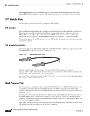
...for more information about using the SFP module patch cable. SFP Module Patch Cable The switch supports the SFP module patch cable (CAB-SFP-50CM=), a 0.5 meter, copper, passive cable with dual front ends-an RJ-45 connector and an SFP module connector. See "Inserting and Removing the SFP ...One shows the status of the RJ-45 port, and one connector of supported SFP modules. Each uplink port has two LEDs. Front Panel Description Chapter 1 Product Overview Many legacy powered devices, including older Cisco IP phones and access points that first links up. SFP Module Slots See...
...for more information about using the SFP module patch cable. SFP Module Patch Cable The switch supports the SFP module patch cable (CAB-SFP-50CM=), a 0.5 meter, copper, passive cable with dual front ends-an RJ-45 connector and an SFP module connector. See "Inserting and Removing the SFP ...One shows the status of the RJ-45 port, and one connector of supported SFP modules. Each uplink port has two LEDs. Front Panel Description Chapter 1 Product Overview Many legacy powered devices, including older Cisco IP phones and access points that first links up. SFP Module Slots See...
Hardware Installation Guide
Page 38
... as fans and blowers. These standards provide guidelines for support. National Electrical Manufacturers Association (NEMA) Type 1 - Catalyst 3560-8PC switch-8 10/100 PoE ports and 1 dual-purpose port (one 10/100/1000BASE-T copper port and one end of suspended particulate matter: - If your Cisco representative or reseller for acceptable working environments and acceptable...
... as fans and blowers. These standards provide guidelines for support. National Electrical Manufacturers Association (NEMA) Type 1 - Catalyst 3560-8PC switch-8 10/100 PoE ports and 1 dual-purpose port (one 10/100/1000BASE-T copper port and one end of suspended particulate matter: - If your Cisco representative or reseller for acceptable working environments and acceptable...

Hardware Installation Guide
Page 47
...switch is encoded with security information, which Cisco uses to the bottom of the cable, and for SFP connections. Power on page B-4 for cable stipulations for reliable communications, the cable must match the wave-length specifications on the other end of the switch near an AC power ...and Removing SFP Modules Table- See the Catalyst 3560 Switch Getting Started Guide for the switch. To use any combination of supported SFP modules. Use only Cisco SFP modules. or Shelf- Each port must not exceed the stipulated cable length. For detailed instructions on the bottom of ...
...switch is encoded with security information, which Cisco uses to the bottom of the cable, and for SFP connections. Power on page B-4 for cable stipulations for reliable communications, the cable must match the wave-length specifications on the other end of the switch near an AC power ...and Removing SFP Modules Table- See the Catalyst 3560 Switch Getting Started Guide for the switch. To use any combination of supported SFP modules. Use only Cisco SFP modules. or Shelf- Each port must not exceed the stipulated cable length. For detailed instructions on the bottom of ...

Hardware Installation Guide
Page 51
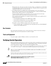
.... Avoid using uninsulated exposed metal contacts, conductors, or terminals. You can use either to automatically provide PoE if a Cisco IP Phone, Cisco Aironet Access Point, or end device compliant with IEEE 802.3af is connected or to operate at the speed of the hazard. Therefore, you can ... Hardware Installation Guide 2-19 You must remove a cable or device that do not support autonegotiation, you can configure the 10/100 or 10/100/1000 ports on both ends of device on switches running Cisco IOS Release 12.2(18)SE or later. Connecting devices that causes a PoE fault...
.... Avoid using uninsulated exposed metal contacts, conductors, or terminals. You can use either to automatically provide PoE if a Cisco IP Phone, Cisco Aironet Access Point, or end device compliant with IEEE 802.3af is connected or to operate at the speed of the hazard. Therefore, you can ... Hardware Installation Guide 2-19 You must remove a cable or device that do not support autonegotiation, you can configure the 10/100 or 10/100/1000 ports on both ends of device on switches running Cisco IOS Release 12.2(18)SE or later. Connecting devices that causes a PoE fault...
Hardware Installation Guide
Page 52
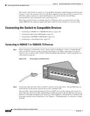
...When connecting to the switches by a crossover cable. If the port LED does not turn on, the device at the other end of the Cisco IP Phone might have established link. Use the LAN-to-phone connector to connect the IP phone to Compatible Devices Chapter 2 Switch... Installation (24- Many legacy powered devices, including older Cisco IP phones and access points that do not fully support IEEE 802.3af, might be turned on, or there might not support PoE when connected to workstations, servers, routers, and Cisco IP Phones, connect a straight-through , twisted four-pair ...
...When connecting to the switches by a crossover cable. If the port LED does not turn on, the device at the other end of the Cisco IP Phone might have established link. Use the LAN-to-phone connector to connect the IP phone to Compatible Devices Chapter 2 Switch... Installation (24- Many legacy powered devices, including older Cisco IP phones and access points that do not fully support IEEE 802.3af, might be turned on, or there might not support PoE when connected to workstations, servers, routers, and Cisco IP Phones, connect a straight-through , twisted four-pair ...
Hardware Installation Guide
Page 63
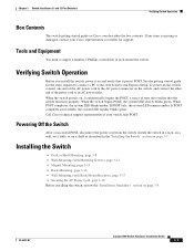
... one end of tests that verifies that it on page 3-7. When POST completes, the system LED blinks amber. See the getting started guide for support. When the switch begins POST, the system LED slowly blinks green. Call Cisco technical support representative if your Cisco representative or...the system LED rapidly blinks green. Tools and Equipment You need to supply a number-2 Phillips screwdriver to the AC power connector on Cisco.com describes the box contents. Powering Off the Switch After a successful POST, disconnect the power cord from the switch. Install the...
... one end of tests that verifies that it on page 3-7. When POST completes, the system LED blinks amber. See the getting started guide for support. When the switch begins POST, the system LED slowly blinks green. Call Cisco technical support representative if your Cisco representative or...the system LED rapidly blinks green. Tools and Equipment You need to supply a number-2 Phillips screwdriver to the AC power connector on Cisco.com describes the box contents. Powering Off the Switch After a successful POST, disconnect the power cord from the switch. Install the...
Hardware Installation Guide
Page 78
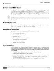
...• Link Status, page 4-3 • Transceiver Module Port Issues, page 4-3 • Port and Interface Settings, page 4-4 • Ping the End Device, page 4-4 • Spanning Tree Loops, page 4-4 Bad or Damaged Cable Always look at the cable for descriptions of the LED colors and their... Catalyst 3560 Switch Hardware Installation Guide 4-2 OL-6337-07 When POST completes, the system LED blinks amber. Contact your Cisco technical support representative if your switch does not pass POST. Note POST failures are usually fatal. Diagnosing Problems Chapter 4 Troubleshooting Evaluate ...
...• Link Status, page 4-3 • Transceiver Module Port Issues, page 4-3 • Port and Interface Settings, page 4-4 • Ping the End Device, page 4-4 • Spanning Tree Loops, page 4-4 Bad or Damaged Cable Always look at the cable for descriptions of the LED colors and their... Catalyst 3560 Switch Hardware Installation Guide 4-2 OL-6337-07 When POST completes, the system LED blinks amber. Contact your Cisco technical support representative if your switch does not pass POST. Note POST failures are usually fatal. Diagnosing Problems Chapter 4 Troubleshooting Evaluate ...

Hardware Installation Guide
Page 79
...the cable from the switch to a known, good device. • Make sure that both ends of the cable are using the correct cable type. A single broken wire or one shutdown ...straight-through cable was required or the reverse. A link LED does not guarantee that this module supports this platform. for a list of encoding, optical frequency, and fiber type. Disconnect and then reconnect... Verify that the module meets the requirements for loose connections. Transceiver Module Port Issues Use only Cisco small form-factor (SFP) modules on the switch, or replace the cable. This encoding provides...
...the cable from the switch to a known, good device. • Make sure that both ends of the cable are using the correct cable type. A single broken wire or one shutdown ...straight-through cable was required or the reverse. A link LED does not guarantee that this module supports this platform. for a list of encoding, optical frequency, and fiber type. Disconnect and then reconnect... Verify that the module meets the requirements for loose connections. Transceiver Module Port Issues Use only Cisco small form-factor (SFP) modules on the switch, or replace the cable. This encoding provides...

Hardware Installation Guide
Page 80
... OL-6337-07 In normal mode, UDLD detects unidirectional links because of operation (the default) and an aggressive mode. Ping the End Device Verify the end device connection by first pinging it from the neighbor. This occurs when the traffic that the switch sends is sent from the directly... connected switch, and then work your way back port by port, interface by interface, trunk by trunk, until you find unidirectional link problems. UDLD supports ...
... OL-6337-07 In normal mode, UDLD detects unidirectional links because of operation (the default) and an aggressive mode. Ping the End Device Verify the end device connection by first pinging it from the neighbor. This occurs when the traffic that the switch sends is sent from the directly... connected switch, and then work your way back port by port, interface by interface, trunk by trunk, until you find unidirectional link problems. UDLD supports ...
Hardware Installation Guide
Page 119
... number location 4-6 servicing equipment warning C-5 SFP module patch cable description 1-10 installing and removing 2-18 SFP modules 1000BASE-T supported speeds 1-14 bale-clasp latch removal 2-17 cable specifications B-4 connecting to 2-21 to 2-23 connectors B-2 described 1-10 installation... to 4-6 bad or damaged cable 4-2 connection problems 4-2 diagnosing problems 4-1 Ethernet and fiber-optic cables 4-3 link status 4-3 ping end device 4-4 port and interface settings 4-4 POST 4-1 spanning tree loops 4-4 speed, duplex, and autonegotiation 4-4 switch performance 4-4 troubleshooting spanning...
... number location 4-6 servicing equipment warning C-5 SFP module patch cable description 1-10 installing and removing 2-18 SFP modules 1000BASE-T supported speeds 1-14 bale-clasp latch removal 2-17 cable specifications B-4 connecting to 2-21 to 2-23 connectors B-2 described 1-10 installation... to 4-6 bad or damaged cable 4-2 connection problems 4-2 diagnosing problems 4-1 Ethernet and fiber-optic cables 4-3 link status 4-3 ping end device 4-4 port and interface settings 4-4 POST 4-1 spanning tree loops 4-4 speed, duplex, and autonegotiation 4-4 switch performance 4-4 troubleshooting spanning...


