
Hardware Installation Guide
Page 3
... 1-1 Front Panel Description 1-3 Fast Ethernet Switch Front Panel Descriptions 1-3 Gigabit Ethernet Switch Front Panel Descriptions 1-6 10/100 and 10/100/1000 Ports 1-8 PoE Ports 1-9 SFP Module Slots 1-10 SFP Modules 1-10 SFP Module Patch Cable 1-10 Dual-Purpose Port 1-10 LEDs 1-11 System LED 1-11 RPS LED... Dual-Purpose Port LEDs 1-15 Cable Guard 1-15 Rear Panel Description 1-15 Internal Power Supply 1-18 DC Power Connector 1-18 Cisco RPS 1-19 Cisco RPS 2300 1-19 Cisco RPS 675 1-19 Console Port 1-19 Security Slots 1-20 Management Options 1-20 Catalyst 3560 Switch Hardware Installation Guide iii
... 1-1 Front Panel Description 1-3 Fast Ethernet Switch Front Panel Descriptions 1-3 Gigabit Ethernet Switch Front Panel Descriptions 1-6 10/100 and 10/100/1000 Ports 1-8 PoE Ports 1-9 SFP Module Slots 1-10 SFP Modules 1-10 SFP Module Patch Cable 1-10 Dual-Purpose Port 1-10 LEDs 1-11 System LED 1-11 RPS LED... Dual-Purpose Port LEDs 1-15 Cable Guard 1-15 Rear Panel Description 1-15 Internal Power Supply 1-18 DC Power Connector 1-18 Cisco RPS 1-19 Cisco RPS 2300 1-19 Cisco RPS 675 1-19 Console Port 1-19 Security Slots 1-20 Management Options 1-20 Catalyst 3560 Switch Hardware Installation Guide iii

Hardware Installation Guide
Page 11
... might deploy the switch. The Catalyst 3560-8PC and the Catalyst 3560-12PC-S compact switches provide the same Power over Ethernet (PoE) connectivity and can be deployed as backbone switches, aggregating 10BASE-T and 100BASE-TX Ethernet traffic from other switches. and 48-port... Catalyst 3560 switches can connect devices like workstations, Cisco Wireless Access Points, Cisco IP Phones, and other network devices such as servers, routers, and other network devices. See the switch software configuration guide...
... might deploy the switch. The Catalyst 3560-8PC and the Catalyst 3560-12PC-S compact switches provide the same Power over Ethernet (PoE) connectivity and can be deployed as backbone switches, aggregating 10BASE-T and 100BASE-TX Ethernet traffic from other switches. and 48-port... Catalyst 3560 switches can connect devices like workstations, Cisco Wireless Access Points, Cisco IP Phones, and other network devices such as servers, routers, and other network devices. See the switch software configuration guide...

Hardware Installation Guide
Page 12
... and 4 SFP module slots Catalyst 3560G-24TS 24 10/100/1000 ports and 4 SFP module slots Catalyst 3560G-48PS 48 10/100/1000 PoE ports and 4 SFP module slots Catalyst 3560G-48TS 48 10/100/1000 ports and 4 SFP module slots 1. Supported SFP modules: • ...100BASE-BX10 (only Catalyst 3560 8- and 48-port switches) • 1000BASE-ZX • Coarse Wavelength-Division Multiplexing (CWDM) • SFP module patch cable. (CAB-SFP-50CM=.) Switches running Cisco...
... and 4 SFP module slots Catalyst 3560G-24TS 24 10/100/1000 ports and 4 SFP module slots Catalyst 3560G-48PS 48 10/100/1000 PoE ports and 4 SFP module slots Catalyst 3560G-48TS 48 10/100/1000 ports and 4 SFP module slots 1. Supported SFP modules: • ...100BASE-BX10 (only Catalyst 3560 8- and 48-port switches) • 1000BASE-ZX • Coarse Wavelength-Division Multiplexing (CWDM) • SFP module patch cable. (CAB-SFP-50CM=.) Switches running Cisco...

Hardware Installation Guide
Page 13
... on page 1-3 • Catalyst 3560-24TS-S, 3560V2-24TS, and 3560V2-24TS-SD Switch Front Panel, Figure 1-2 on page 1-4 • Catalyst 3560-48PS and 3560V2-48PS Switch Front Panel, Figure 1-3 on page 1-4 • Catalyst 3560-48TS-S and 3560V2-48TS Switch Front Panel, Figure 1-4 on page 1-5 • ...Catalyst 3560-8PC Switch Front Panel, Figure 1-5 on page 1-5 • Catalyst 3560-12PC-S Switch Front Panel, Figure 1-6 on page 1-6 The 10/100 PoE ...
... on page 1-3 • Catalyst 3560-24TS-S, 3560V2-24TS, and 3560V2-24TS-SD Switch Front Panel, Figure 1-2 on page 1-4 • Catalyst 3560-48PS and 3560V2-48PS Switch Front Panel, Figure 1-3 on page 1-4 • Catalyst 3560-48TS-S and 3560V2-48TS Switch Front Panel, Figure 1-4 on page 1-5 • ...Catalyst 3560-8PC Switch Front Panel, Figure 1-5 on page 1-5 • Catalyst 3560-12PC-S Switch Front Panel, Figure 1-6 on page 1-6 The 10/100 PoE ...

Hardware Installation Guide
Page 14
Figure 1-3 Catalyst 3560-48PS and 3560V2-48PS Switch Front Panel 97911 SYST RPS STAT DUPLX SPEED PoE MODE 1 1X 2X 23 45 67 8 9 10 11 12 13 14 15...35 36 37 38 39 40 41 42 43 44 45 46 47 48 Catalyst 3560 SERIES PoE-48 47X 32X 34X 1 3 48X 2 4 1 2 1 10/100 PoE ports 2 SFP module slots Catalyst 3560 Switch Hardware Installation Guide 1-4 OL-6337-07 The ... 23 24 23X Catalyst 3560 SERIES 14X 24X 1 2 1 2 1 10/100 ports 2 SFP module slots The 10/100 PoE ports on the switch are grouped in pairs. Port 3 is above port 4, and so on. The first member of the ...
Figure 1-3 Catalyst 3560-48PS and 3560V2-48PS Switch Front Panel 97911 SYST RPS STAT DUPLX SPEED PoE MODE 1 1X 2X 23 45 67 8 9 10 11 12 13 14 15...35 36 37 38 39 40 41 42 43 44 45 46 47 48 Catalyst 3560 SERIES PoE-48 47X 32X 34X 1 3 48X 2 4 1 2 1 10/100 PoE ports 2 SFP module slots Catalyst 3560 Switch Hardware Installation Guide 1-4 OL-6337-07 The ... 23 24 23X Catalyst 3560 SERIES 14X 24X 1 2 1 2 1 10/100 ports 2 SFP module slots The 10/100 PoE ports on the switch are grouped in pairs. Port 3 is above port 4, and so on. The first member of the ...

Hardware Installation Guide
Page 15
... Front Panel SYST STAT DPLX SPD MODE CONSOLE 1x 2x 3x 4x 5x 6x 7x 8x Catalyst 2960 Series 1 157822 1 2 3 1 Console port 2 10/100 PoE ports 3 Dual-purpose port OL-6337-07 Catalyst 3560 Switch Hardware Installation Guide 1-5 The dual-purpose port can use either an RJ-45 connector or... 43 44 45 46 47 48 47X 32X 34X Catalyst 3560 SERIES 1 3 48X 2 4 1 2 1 10/100 ports 2 SFP module slots The console port, 10/100 PoE ports, and a dual-purpose port are numbered 1 to 4. For more information on the dual-purpose port, see the "Console Port" section on the front panel...
... Front Panel SYST STAT DPLX SPD MODE CONSOLE 1x 2x 3x 4x 5x 6x 7x 8x Catalyst 2960 Series 1 157822 1 2 3 1 Console port 2 10/100 PoE ports 3 Dual-purpose port OL-6337-07 Catalyst 3560 Switch Hardware Installation Guide 1-5 The dual-purpose port can use either an RJ-45 connector or... 43 44 45 46 47 48 47X 32X 34X Catalyst 3560 SERIES 1 3 48X 2 4 1 2 1 10/100 ports 2 SFP module slots The console port, 10/100 PoE ports, and a dual-purpose port are numbered 1 to 4. For more information on the dual-purpose port, see the "Console Port" section on the front panel...

Hardware Installation Guide
Page 16
...1 3 1 Console port 2 10/100 PoE ports 3 Dual-purpose port Gigabit Ethernet Switch Front Panel Descriptions • Catalyst 3560G-24PS Switch Front Panel, Figure 1-7 on page 1-6 • Catalyst 3560G-24TS Switch Front Panel, Figure 1-8 on page 1-7 • Catalyst 3560G-48PS Switch Front Panel, Figure 1-9 on page 1-7... • Catalyst 3560G-48TS Switch Front Panel, Figure 1-10 on page 1-8 The 10/100/1000 PoE ports on the left, as shown in pairs. Figure 1-7 Catalyst 3560G...
...1 3 1 Console port 2 10/100 PoE ports 3 Dual-purpose port Gigabit Ethernet Switch Front Panel Descriptions • Catalyst 3560G-24PS Switch Front Panel, Figure 1-7 on page 1-6 • Catalyst 3560G-24TS Switch Front Panel, Figure 1-8 on page 1-7 • Catalyst 3560G-48PS Switch Front Panel, Figure 1-9 on page 1-7... • Catalyst 3560G-48TS Switch Front Panel, Figure 1-10 on page 1-8 The 10/100/1000 PoE ports on the left, as shown in pairs. Figure 1-7 Catalyst 3560G...

Hardware Installation Guide
Page 17
... 24X 26 28 1 2 1 10/100/1000 ports 2 SFP module slots The 10/100/1000 PoE ports on the Catalyst 3560G-48PS switch are grouped in Figure 1-8. Figure 1-9 Catalyst 3560G-48PS Switch Front Panel 119674 SYST RPS STAT DUPLX SPEED PoE MODE 1 1X 2X 23 45 67 8 9 10 11 12 13 14 15 16 17... 31 32 16X 18X 33 31X 33X 34 35 36 37 38 39 40 41 42 43 44 45 46 47 48 Catalyst 3560G SERIES PoE-48 47X 32X 34X 49 51 48X 50 52 1 2 1 10/100/1000 ports 2 SFP module slots OL-6337-07 Catalyst 3560 Switch Hardware Installation Guide...
... 24X 26 28 1 2 1 10/100/1000 ports 2 SFP module slots The 10/100/1000 PoE ports on the Catalyst 3560G-48PS switch are grouped in Figure 1-8. Figure 1-9 Catalyst 3560G-48PS Switch Front Panel 119674 SYST RPS STAT DUPLX SPEED PoE MODE 1 1X 2X 23 45 67 8 9 10 11 12 13 14 15 16 17... 31 32 16X 18X 33 31X 33X 34 35 36 37 38 39 40 41 42 43 44 45 46 47 48 Catalyst 3560G SERIES PoE-48 47X 32X 34X 49 51 48X 50 52 1 2 1 10/100/1000 ports 2 SFP module slots OL-6337-07 Catalyst 3560 Switch Hardware Installation Guide...

Hardware Installation Guide
Page 18
... device also supports autonegotiation, the switch port negotiates the best connection (the fastest line speed that present a shock hazard may exist on Power over Ethernet (PoE) circuits if interconnections are made aware of the attached device and advertises its own capabilities. Port 3 is 1000 Mb/s. • When set for speed and...
... device also supports autonegotiation, the switch port negotiates the best connection (the fastest line speed that present a shock hazard may exist on Power over Ethernet (PoE) circuits if interconnections are made aware of the attached device and advertises its own capabilities. Port 3 is 1000 Mb/s. • When set for speed and...

Hardware Installation Guide
Page 19
... IP phone, or a Cisco prestandard Cisco access point, is disabled by default on switches running Cisco IOS Release 12.2(18)SE or later. On the Catalyst 3560-48PS, 3560G-48PS, and 3560V2-48PS switches, any 24 of the 48 10/100 or 10/100/1000 ports delivers 15.4 W of PoE, or any combination of the ports ...delivers an average of 7.7 W of PoE at the same time...
... IP phone, or a Cisco prestandard Cisco access point, is disabled by default on switches running Cisco IOS Release 12.2(18)SE or later. On the Catalyst 3560-48PS, 3560G-48PS, and 3560V2-48PS switches, any 24 of the 48 10/100 or 10/100/1000 ports delivers 15.4 W of PoE, or any combination of the ports ...delivers an average of 7.7 W of PoE at the same time...
Hardware Installation Guide
Page 20
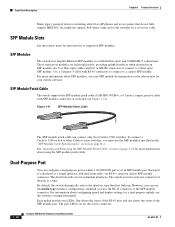
Front Panel Description Chapter 1 Product Overview Many legacy powered devices, including older Cisco IP phones and access points that first links up. These transceiver modules are not redundant interfaces. Use a Category 5 cable with LC or MT-RJ connectors ... uplink port has two LEDs. By default, the switch dynamically selects the interface type that do not fully support IEEE 802.3af, might not support PoE when connected to a copper SFP module. For information about using the SFP module patch cable. To connect a Catalyst 3560 switch to establish fiber-optic and...
Front Panel Description Chapter 1 Product Overview Many legacy powered devices, including older Cisco IP phones and access points that first links up. These transceiver modules are not redundant interfaces. Use a Category 5 cable with LC or MT-RJ connectors ... uplink port has two LEDs. By default, the switch dynamically selects the interface type that do not fully support IEEE 802.3af, might not support PoE when connected to a copper SFP module. For information about using the SFP module patch cable. To connect a Catalyst 3560 switch to establish fiber-optic and...

Hardware Installation Guide
Page 21
... LEDs 1. For information on the System LED colors during the power-on self-test (POST), see the "Verifying Switch Operation" section on the Catalyst 3560 PoE switches. 2. Figure 1-12 shows the switch LEDs and the Mode button that you use to monitor switch activity and its performance. The... PoE LED is not powered on. Table 1-2 Color Off Green Amber System LED System Status System is only on page 2-6. All the LEDs described here are ...
... LEDs 1. For information on the System LED colors during the power-on self-test (POST), see the "Verifying Switch Operation" section on the Catalyst 3560 PoE switches. 2. Figure 1-12 shows the switch LEDs and the Mode button that you use to monitor switch activity and its performance. The... PoE LED is not powered on. Table 1-2 Color Off Green Amber System LED System Status System is only on page 2-6. All the LEDs described here are ...

Hardware Installation Guide
Page 23
... at 10 or 100 Mb/s in different port modes. The port operating speed: 10, 100, or 10001 Mb/s. PoE mode is selected, and the PoE status is not selected. The PoE LED applies only to interpret the port LED colors in half-duplex mode. Table 1-6 explains how to Catalyst 3560 switches... individual ports: Table 1-4 Modes for Port LEDs Selected Mode LED Port Mode Description STAT Port status The port status. Even if the PoE mode is highlighted. PoE mode is shown on the port LEDs. To select or change . OL-6337-07 Catalyst 3560 Switch Hardware Installation Guide 1-13 When ...
... at 10 or 100 Mb/s in different port modes. The port operating speed: 10, 100, or 10001 Mb/s. PoE mode is selected, and the PoE status is not selected. The PoE LED applies only to interpret the port LED colors in half-duplex mode. Table 1-6 explains how to Catalyst 3560 switches... individual ports: Table 1-4 Modes for Port LEDs Selected Mode LED Port Mode Description STAT Port status The port status. Even if the PoE mode is highlighted. PoE mode is shown on the port LEDs. To select or change . OL-6337-07 Catalyst 3560 Switch Hardware Installation Guide 1-13 When ...

Hardware Installation Guide
Page 24
... seconds as excessive collisions, cyclic redundancy check (CRC) errors, and alignment and jabber errors are connected to PoE ports. Alternating green-amber Link fault. Blinking green Activity. PoE is reconfigured, the port LED can be used to connect Cisco prestandard IP Phones or wireless access points or IEEE 802.3af-compliant devices to...
... seconds as excessive collisions, cyclic redundancy check (CRC) errors, and alignment and jabber errors are connected to PoE ports. Alternating green-amber Link fault. Blinking green Activity. PoE is reconfigured, the port LED can be used to connect Cisco prestandard IP Phones or wireless access points or IEEE 802.3af-compliant devices to...
Hardware Installation Guide
Page 36
... following ports must be made first and disconnected last. Contact the appropriate electrical inspection authority or an electrician if you work on Power over Ethernet (PoE) circuits if interconnections are in a situation that could cause bodily injury. All connections must be familiar with local and national electrical codes. Statement 1028 Warning...
... following ports must be made first and disconnected last. Contact the appropriate electrical inspection authority or an electrician if you work on Power over Ethernet (PoE) circuits if interconnections are in a situation that could cause bodily injury. All connections must be familiar with local and national electrical codes. Statement 1028 Warning...

Hardware Installation Guide
Page 37
.... and 48-Port Switches) Statement 371-Power Cable and AC Adapter Preparing for Installation Caution To comply with the Telcordia GR-1089 NEBS standard, PoE or non-PoE 10/100/1000 Ethernet port cables that might damage the cables. • For copper Ethernet ports, including 10/100 ports, 10/100/1000 ports...
.... and 48-Port Switches) Statement 371-Power Cable and AC Adapter Preparing for Installation Caution To comply with the Telcordia GR-1089 NEBS standard, PoE or non-PoE 10/100/1000 Ethernet port cables that might damage the cables. • For copper Ethernet ports, including 10/100 ports, 10/100/1000 ports...
Hardware Installation Guide
Page 38
Catalyst 3560-8PC switch-8 10/100 PoE ports and 1 dual-purpose port (one 10/100/1000BASE-T copper...and the RPS to an AC power outlet. However, these fans and blowers can result in a system malfunction. If your Cisco representative or reseller for this equipment in a rack, on a wall, or on a table or shelf, you should insert...3560 Switch Hardware Installation Guide 2-6 OL-6337-07 National Electrical Manufacturers Association (NEMA) Type 1 - See the "Cisco RPS" section on Cisco.com describes the box contents. Set the RPS to the RPS receptacle: PWR-RPS2300, PWR675-AC-RPS-N1=. ...
Catalyst 3560-8PC switch-8 10/100 PoE ports and 1 dual-purpose port (one 10/100/1000BASE-T copper...and the RPS to an AC power outlet. However, these fans and blowers can result in a system malfunction. If your Cisco representative or reseller for this equipment in a rack, on a wall, or on a table or shelf, you should insert...3560 Switch Hardware Installation Guide 2-6 OL-6337-07 National Electrical Manufacturers Association (NEMA) Type 1 - See the "Cisco RPS" section on Cisco.com describes the box contents. Set the RPS to the RPS receptacle: PWR-RPS2300, PWR675-AC-RPS-N1=. ...

Hardware Installation Guide
Page 40
... screws (see Figure 2-1.) Figure 2-1 Removing Screws from the Catalyst 3560 Switch 97916 40 41 42 43 44 45 46 47 48 47X Catalyst 3560 SERIES PoE-48 1 3 48X 2 4 Attaching Brackets to the Catalyst 3560 Switch The bracket orientation and the brackets that you are attaching the brackets for 19-Inch ...Racks to a Catalyst 3560 Switch, Front Panel Forward SYST RPS STAT DUPLX SPEED PoE MODE 1 1X 23 45 67 8 9 10 11 12 13 14 15 16 15X 2X 16X 1 Phillips flat-head screws 97917 Catalyst 3560 Switch Hardware ...
... screws (see Figure 2-1.) Figure 2-1 Removing Screws from the Catalyst 3560 Switch 97916 40 41 42 43 44 45 46 47 48 47X Catalyst 3560 SERIES PoE-48 1 3 48X 2 4 Attaching Brackets to the Catalyst 3560 Switch The bracket orientation and the brackets that you are attaching the brackets for 19-Inch ...Racks to a Catalyst 3560 Switch, Front Panel Forward SYST RPS STAT DUPLX SPEED PoE MODE 1 1X 23 45 67 8 9 10 11 12 13 14 15 16 15X 2X 16X 1 Phillips flat-head screws 97917 Catalyst 3560 Switch Hardware ...

Hardware Installation Guide
Page 41
... the Switch Figure 2-3 1 Attaching Brackets for 24-Inch Racks to a Catalyst 3560 Switch, Front Panel Forward 1 Phillips flat-head screws SYST RPS STAT DUPLX SPEED PoE MODE 1 1X 23 45 67 8 9 10 11 12 13 14 15 16 15X 2X 16X 97918 Figure 2-4 Attaching Brackets for 19-Inch Racks to a Catalyst...
... the Switch Figure 2-3 1 Attaching Brackets for 24-Inch Racks to a Catalyst 3560 Switch, Front Panel Forward 1 Phillips flat-head screws SYST RPS STAT DUPLX SPEED PoE MODE 1 1X 23 45 67 8 9 10 11 12 13 14 15 16 15X 2X 16X 97918 Figure 2-4 Attaching Brackets for 19-Inch Racks to a Catalyst...

Hardware Installation Guide
Page 42
... 2-6 Attaching Brackets for 19-Inch Telco Racks to a Catalyst 3560 Switch 97921 40 41 42 43 44 45 46 47 48 47X Catalyst 3560 SERIES PoE-48 1 3 48X 2 4 1 1 Phillips flat-head screws Figure 2-7 Attaching Brackets for 24-Inch Telco Racks to a Catalyst 3560 Switch 97922 40 41 42 43 44... 45 46 47 48 47X Catalyst 3560 SERIES PoE-48 1 3 48X 2 1 4 1 Phillips flat-head screws Mounting the Switch in a Rack After the brackets are attached to the switch, use the four supplied ...
... 2-6 Attaching Brackets for 19-Inch Telco Racks to a Catalyst 3560 Switch 97921 40 41 42 43 44 45 46 47 48 47X Catalyst 3560 SERIES PoE-48 1 3 48X 2 4 1 1 Phillips flat-head screws Figure 2-7 Attaching Brackets for 24-Inch Telco Racks to a Catalyst 3560 Switch 97922 40 41 42 43 44... 45 46 47 48 47X Catalyst 3560 SERIES PoE-48 1 3 48X 2 1 4 1 Phillips flat-head screws Mounting the Switch in a Rack After the brackets are attached to the switch, use the four supplied ...
