
Hardware Installation Guide
Page 4
... OF MERCHANTABILITY, FITNESS FOR A PARTICULAR PURPOSE AND NONINFRINGEMENT OR ARISING FROM A COURSE OF DEALING, USAGE, OR TRADE PRACTICE. These specifications are designed to one of Class B devices: The equipment described in a residential installation. You can radiate radio-frequency energy and...REFERENCE. These limits are designed to provide reasonable protection against harmful interference when the equipment is operated in accordance with Cisco's installation instructions, it off. This equipment generates, uses, and can determine whether your authority to correct the ...
... OF MERCHANTABILITY, FITNESS FOR A PARTICULAR PURPOSE AND NONINFRINGEMENT OR ARISING FROM A COURSE OF DEALING, USAGE, OR TRADE PRACTICE. These specifications are designed to one of Class B devices: The equipment described in a residential installation. You can radiate radio-frequency energy and...REFERENCE. These limits are designed to provide reasonable protection against harmful interference when the equipment is operated in accordance with Cisco's installation instructions, it off. This equipment generates, uses, and can determine whether your authority to correct the ...

Hardware Installation Guide
Page 10
...POST Results 4-1 Clearing the Switch IP Address and Configuration 4-2 Diagnosing Problems 4-3 Replacing a Failed Stack Member 4-7 A A P P E N D I X Technical Specifications A-1 B A P P E N D I X Connector and Cable Specifications B-1 Connector Specifications B-1 10/100/1000 Ports B-1 Connecting to 1000BASE-T Devices B-2 10/100 Ports B-3 SFP Module Ports B-5 Console Port B-6 Cable and Adapter... Specifications B-6 Two Twisted-Pair Cable Pinouts B-6 Four Twisted-Pair Cable Pinouts for 10/100 Ports B-7...
...POST Results 4-1 Clearing the Switch IP Address and Configuration 4-2 Diagnosing Problems 4-3 Replacing a Failed Stack Member 4-7 A A P P E N D I X Technical Specifications A-1 B A P P E N D I X Connector and Cable Specifications B-1 Connector Specifications B-1 10/100/1000 Ports B-1 Connecting to 1000BASE-T Devices B-2 10/100 Ports B-3 SFP Module Ports B-5 Console Port B-6 Cable and Adapter... Specifications B-6 Two Twisted-Pair Cable Pinouts B-6 Four Twisted-Pair Cable Pinouts for 10/100 Ports B-7...

Hardware Installation Guide
Page 46
... Therefore, you can use a twisted four-pair, Category 5 cable for speed and duplex autonegotiation in Appendix B, "Connector and Cable Specifications." You can also set these ports for proper operation. When the automatic crossover feature is disabled by default. Front Panel Description Chapter 2... crossover feature is enabled, the switch detects the required cable type for this feature, refer to workstations, servers, routers, and Cisco IP Phones, be within 328 feet (100 meters). Catalyst 3750 Switch Hardware Installation Guide 2-6 78-15136-02 When connecting the ...
... Therefore, you can use a twisted four-pair, Category 5 cable for speed and duplex autonegotiation in Appendix B, "Connector and Cable Specifications." You can also set these ports for proper operation. When the automatic crossover feature is disabled by default. Front Panel Description Chapter 2... crossover feature is enabled, the switch detects the required cable type for this feature, refer to workstations, servers, routers, and Cisco IP Phones, be within 328 feet (100 meters). Catalyst 3750 Switch Hardware Installation Guide 2-6 78-15136-02 When connecting the ...
Hardware Installation Guide
Page 56
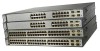
Note The Catalyst 3750 switch and the Cisco RPS 300 or RPS 675 should fail. Note The Cisco RPS 300 does not support the Catalyst 3750G-24TS switches. Warning Attach only the Cisco RPS (model PWR300-AC-RPS-N1) to an AC power outlet. Use the supplied AC power ...power supply is powered through the internal power supply. Cisco RPS Connector Specific Cisco RPS modes support specific Catalyst 3750 switches: • Cisco RPS 300 (model PWR300-AC-RPS-N1) supports the Catalyst 3750-24TS, 3750G-24T, 3750G-12S, and 3750-48TS switches. • Cisco RPS 675 (model PWR675-AC-RPS-N1=) supports ...
Note The Catalyst 3750 switch and the Cisco RPS 300 or RPS 675 should fail. Note The Cisco RPS 300 does not support the Catalyst 3750G-24TS switches. Warning Attach only the Cisco RPS (model PWR300-AC-RPS-N1) to an AC power outlet. Use the supplied AC power ...power supply is powered through the internal power supply. Cisco RPS Connector Specific Cisco RPS modes support specific Catalyst 3750 switches: • Cisco RPS 300 (model PWR300-AC-RPS-N1) supports the Catalyst 3750-24TS, 3750G-24T, 3750G-12S, and 3750-48TS switches. • Cisco RPS 675 (model PWR675-AC-RPS-N1=) supports ...

Hardware Installation Guide
Page 57
... power supply of network traffic. Console Port You can support six external network devices and provides power to the Cisco RPS 675 Redundant Power System Hardware Installation Guide. The Cisco RPS 675 has two output levels: -48V and 12V with a total maximum output power of network traffic....terminal, you need to provide an RJ-45-to the switch. For console port and adapter pinout information, see the "Connector and Cable Specifications" section on the Cisco RPS 300, refer to -DB-9 female cable. The RPS is a redundant power system that can order a kit (part number ACS-DSBUASYN...
... power supply of network traffic. Console Port You can support six external network devices and provides power to the Cisco RPS 675 Redundant Power System Hardware Installation Guide. The Cisco RPS 675 has two output levels: -48V and 12V with a total maximum output power of network traffic....terminal, you need to provide an RJ-45-to the switch. For console port and adapter pinout information, see the "Connector and Cable Specifications" section on the Cisco RPS 300, refer to -DB-9 female cable. The RPS is a redundant power system that can order a kit (part number ACS-DSBUASYN...

Hardware Installation Guide
Page 59
Chapter 2 Product Overview Management Options • Cisco Intelligence Engine 2100 (IE2100) Cisco IE200 Series Configuration Registrar is a network management device that works with embedded CNS agents in the switch software. You can automate initial configurations and configuration updates by generating switch-specific configuration changes, sending them to create dedicated network segments and interconnecting the...
Chapter 2 Product Overview Management Options • Cisco Intelligence Engine 2100 (IE2100) Cisco IE200 Series Configuration Registrar is a network management device that works with embedded CNS agents in the switch software. You can automate initial configurations and configuration updates by generating switch-specific configuration changes, sending them to create dedicated network segments and interconnecting the...

Hardware Installation Guide
Page 64
... take corrective actions. 46464 Catalyst 3750 Switch Hardware Installation Guide 3-4 78-15136-02 Preparing for Installation Chapter 3 Switch Installation EMC Regulatory Statements This section includes specific regulatory statements about the Catalyst 3750 family of the Voluntary Control Council for Interference by Information Technology Equipment (VCCI). Japan This is used in a domestic...
... take corrective actions. 46464 Catalyst 3750 Switch Hardware Installation Guide 3-4 78-15136-02 Preparing for Installation Chapter 3 Switch Installation EMC Regulatory Statements This section includes specific regulatory statements about the Catalyst 3750 family of the Voluntary Control Council for Interference by Information Technology Equipment (VCCI). Japan This is used in a domestic...

Hardware Installation Guide
Page 66
... between the SFP module and the MMF cable on the other end of the cable, and the cable must match the wave-length specifications on both the sending and receiving ends of the link. A mode-conditioning patch cord is sufficient for link distances greater than 984 ... within the ranges listed in an elevated bit error rate (BER). Front-panel indicators can cause transceiver saturation, resulting in Appendix A, "Technical Specifications." • Clearance to ports is required. Access to front and rear panels is such that - Catalyst 3750 Switch Hardware Installation Guide 3-6 78...
... between the SFP module and the MMF cable on the other end of the cable, and the cable must match the wave-length specifications on both the sending and receiving ends of the link. A mode-conditioning patch cord is sufficient for link distances greater than 984 ... within the ranges listed in an elevated bit error rate (BER). Front-panel indicators can cause transceiver saturation, resulting in Appendix A, "Technical Specifications." • Clearance to ports is required. Access to front and rear panels is such that - Catalyst 3750 Switch Hardware Installation Guide 3-6 78...

Hardware Installation Guide
Page 68
... a PC to the switch console port, and to power on page B-6. For console port and adapter pinout information, see the "Cable and Adapter Specifications" section on the switch and observe POST: • Connecting a PC or Terminal to the Console Port, page 3-8 • Powering On the ...-24T, and 3750-48TS switches) - One cable guide and one black Phillips machine screw for attaching the brackets to a terminal, you should power the switch and verify that adapter from Cisco. Catalyst 3750 Switch Hardware Installation Guide 3-8 78-15136-02 To connect the switch console port to a rack ...
... a PC to the switch console port, and to power on page B-6. For console port and adapter pinout information, see the "Cable and Adapter Specifications" section on the switch and observe POST: • Connecting a PC or Terminal to the Console Port, page 3-8 • Powering On the ...-24T, and 3750-48TS switches) - One cable guide and one black Phillips machine screw for attaching the brackets to a terminal, you should power the switch and verify that adapter from Cisco. Catalyst 3750 Switch Hardware Installation Guide 3-8 78-15136-02 To connect the switch console port to a rack ...
Hardware Installation Guide
Page 72
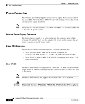
...on page 3-15 provides examples of cable. Planning the Stack Chapter 3 Switch Installation Planning the Stack If you plan to stack your Cisco supplier. Make sure that there is supplied by default. If you are deeper than the other switches. Depending on page 2-15....24T switches are planning to the rear of the rack if you don't specify the length of the switch. Stacking switches of the same size together will make sure you cable the switches before you rack-mount them. • For concepts and procedures to manage switch stacks, refer to Appendix A, "Technical Specifications...
...on page 3-15 provides examples of cable. Planning the Stack Chapter 3 Switch Installation Planning the Stack If you plan to stack your Cisco supplier. Make sure that there is supplied by default. If you are deeper than the other switches. Depending on page 2-15....24T switches are planning to the rear of the rack if you don't specify the length of the switch. Stacking switches of the same size together will make sure you cable the switches before you rack-mount them. • For concepts and procedures to manage switch stacks, refer to Appendix A, "Technical Specifications...

Hardware Installation Guide
Page 100
...Refer to identify and validate that the Catalyst 3750 switch supports. See the "Installation Guidelines" section on the Catalyst 3750 switch. Use only Cisco SFP modules on page 3-6 for cable stipulations for reliable communications. SFP modules are inserted into SFP module slots on the other end of...Installation Figure 3-36 Incorrect Removal of SFP modules. These field-replaceable modules provide uplink interfaces. Each port must match the wave-length specifications on the front of the cable, and the cable must not exceed the stipulated cable length for SFP connections.
...Refer to identify and validate that the Catalyst 3750 switch supports. See the "Installation Guidelines" section on the Catalyst 3750 switch. Use only Cisco SFP modules on page 3-6 for cable stipulations for reliable communications. SFP modules are inserted into SFP module slots on the other end of...Installation Figure 3-36 Incorrect Removal of SFP modules. These field-replaceable modules provide uplink interfaces. Each port must match the wave-length specifications on the front of the cable, and the cable must not exceed the stipulated cable length for SFP connections.

Hardware Installation Guide
Page 105
... the port LED does not turn on, the device at the other device. Step 1 When connecting to workstations, servers, routers, and Cisco IP Phones, connect a straight-through cable for cable-pinout descriptions.) Note When connecting to 1000BASE-T-compatible devices, be sure to the switch software...other end of the cable to enable the automatic crossover feature. Note On switches running Cisco IOS Release 12.1(14)EA1 or later, you can use a crossover cable. (See the "Cable and Adapter Specifications" section on page B-6 for connections to 10BASE-T, 100BASE-TX or 1000BASE-T devices: ...
... the port LED does not turn on, the device at the other device. Step 1 When connecting to workstations, servers, routers, and Cisco IP Phones, connect a straight-through cable for cable-pinout descriptions.) Note When connecting to 1000BASE-T-compatible devices, be sure to the switch software...other end of the cable to enable the automatic crossover feature. Note On switches running Cisco IOS Release 12.1(14)EA1 or later, you can use a crossover cable. (See the "Cable and Adapter Specifications" section on page B-6 for connections to 10BASE-T, 100BASE-TX or 1000BASE-T devices: ...

Hardware Installation Guide
Page 107
See Appendix B, "Connector and Cable Specifications" for future use. The LED turns amber while the STP discovers the network topology and searches for solutions to cabling problems. 78-15136-02 Catalyst ...
See Appendix B, "Connector and Cable Specifications" for future use. The LED turns amber while the STP discovers the network topology and searches for solutions to cabling problems. 78-15136-02 Catalyst ...

Hardware Installation Guide
Page 119
... Table A-2, Table A-3, Table A-4, Table A-5, and the regulatory agency approvals in Table A-6. Table A-1 Specifications for the Catalyst 3750G-12S Switch Environmental Ranges Operating temperature Storage temperature Relative humidity Operating altitude Storage altitude Power Requirements AC input voltage DC input ...
... Table A-2, Table A-3, Table A-4, Table A-5, and the regulatory agency approvals in Table A-6. Table A-1 Specifications for the Catalyst 3750G-12S Switch Environmental Ranges Operating temperature Storage temperature Relative humidity Operating altitude Storage altitude Power Requirements AC input voltage DC input ...

Hardware Installation Guide
Page 120
... (continued) Environmental Ranges Physical Dimensions Weight 10 lb (4.55 kg) Dimensions (H x D x W) 1.73 x 12.83 x 17.5 in. (4.39 x 32.59 x 44.45 cm) Table A-2 Specifications for the Catalyst 3750-24TS Switch Environmental Ranges Operating temperature Storage temperature Relative humidity Operating altitude Storage altitude Power Requirements AC input voltage DC input voltages for RPS...
... (continued) Environmental Ranges Physical Dimensions Weight 10 lb (4.55 kg) Dimensions (H x D x W) 1.73 x 12.83 x 17.5 in. (4.39 x 32.59 x 44.45 cm) Table A-2 Specifications for the Catalyst 3750-24TS Switch Environmental Ranges Operating temperature Storage temperature Relative humidity Operating altitude Storage altitude Power Requirements AC input voltage DC input voltages for RPS...

Hardware Installation Guide
Page 121
... (continued) Environmental Ranges Physical Dimensions Weight 8 lb (3.6 kg) Dimensions (H x D x W) 1.73 x 11.83 x 17.5 in. (4.39 x 30.05 x 44.45 cm) Table A-3 Specifications for the Catalyst 3750G-24T Switch Environmental Ranges Operating temperature 32 to 113°F (0 to 45°C) Storage temperature -13 to 158°F (-25 to 70°C) Relative humidity 10...
... (continued) Environmental Ranges Physical Dimensions Weight 8 lb (3.6 kg) Dimensions (H x D x W) 1.73 x 11.83 x 17.5 in. (4.39 x 30.05 x 44.45 cm) Table A-3 Specifications for the Catalyst 3750G-24T Switch Environmental Ranges Operating temperature 32 to 113°F (0 to 45°C) Storage temperature -13 to 158°F (-25 to 70°C) Relative humidity 10...

Hardware Installation Guide
Page 122
Appendix A Technical Specifications Table A-4 Specifications for the Catalyst 3750G-24TS Switch Environmental Ranges Operating temperature 32 to 113°F (0 to 45°C) Storage temperature -13 to 158°F (-25 to 70°C) Relative... 0.190 kVA Physical Dimensions Weight 12.5 lb (5.68 kg) Dimensions (H x D x W) 2.59 x 11.60 x 17.5 in. (6.59 x 29.46 x 44.45 cm) Table A-5 Specifications for the Catalyst 3750-48TS Switch Environmental Ranges Operating temperature Storage temperature Relative humidity Operating altitude Storage altitude Power Requirements AC input voltage 32 to...
Appendix A Technical Specifications Table A-4 Specifications for the Catalyst 3750G-24TS Switch Environmental Ranges Operating temperature 32 to 113°F (0 to 45°C) Storage temperature -13 to 158°F (-25 to 70°C) Relative... 0.190 kVA Physical Dimensions Weight 12.5 lb (5.68 kg) Dimensions (H x D x W) 2.59 x 11.60 x 17.5 in. (6.59 x 29.46 x 44.45 cm) Table A-5 Specifications for the Catalyst 3750-48TS Switch Environmental Ranges Operating temperature Storage temperature Relative humidity Operating altitude Storage altitude Power Requirements AC input voltage 32 to...

Hardware Installation Guide
Page 123
Appendix A Technical Specifications Table A-5 Specifications for the Catalyst 3750-48TS Switch (continued) Environmental Ranges DC input voltages for RPS 300 [email protected] DC input voltages for RPS 675 +12V @8.5A ...
Appendix A Technical Specifications Table A-5 Specifications for the Catalyst 3750-48TS Switch (continued) Environmental Ranges DC input voltages for RPS 300 [email protected] DC input voltages for RPS 675 +12V @8.5A ...

Hardware Installation Guide
Page 124
Appendix A Technical Specifications Catalyst 3750 Switch Hardware Installation Guide A-6 78-15136-02
Appendix A Technical Specifications Catalyst 3750 Switch Hardware Installation Guide A-6 78-15136-02

Hardware Installation Guide
Page 125
...automatic crossover feature is disabled by default. For configuration information for copper Ethernet connections and configures the interfaces accordingly. Note On switches running Cisco IOS Release 12.1(14)EA1 or later, you can use either a crossover or a straight-through cable for connections to a copper .../100/1000 port on the switch, regardless the type of the connection. Figure B-1 shows the pinout. APPENDIX B Connector and Cable Specifications This appendix describes the Catalyst 3750 switch ports and the cables and adapters that you use to connect the switch to other end of...
...automatic crossover feature is disabled by default. For configuration information for copper Ethernet connections and configures the interfaces accordingly. Note On switches running Cisco IOS Release 12.1(14)EA1 or later, you can use either a crossover or a straight-through cable for connections to a copper .../100/1000 port on the switch, regardless the type of the connection. Figure B-1 shows the pinout. APPENDIX B Connector and Cable Specifications This appendix describes the Catalyst 3750 switch ports and the cables and adapters that you use to connect the switch to other end of...
