Hardware Installation Guide
Page 8
... Go Next 1-12 Other Switch Home Page Features 1-12 Installing or Connecting Devices to the Switch 1-12 Product Overview 2-1 Features 2-1 Front Panel Description 2-3 10/100 and 10/100/1000 Ports 2-6 SFP Module Slots 2-7 SFP Modules 2-7 LEDs 2-8 System LED 2-9 RPS LED 2-9 Master LED... 2-10 Port LEDs and Modes 2-10 Rear Panel Description 2-14 StackWise Ports 2-15 Power Connectors 2-16 Internal Power Supply Connector 2-16 Cisco RPS Connector 2-16 Console Port 2-17 Management Options 2-18 Network Configurations 2-19 Switch Installation 3-1 Preparing for ...
... Go Next 1-12 Other Switch Home Page Features 1-12 Installing or Connecting Devices to the Switch 1-12 Product Overview 2-1 Features 2-1 Front Panel Description 2-3 10/100 and 10/100/1000 Ports 2-6 SFP Module Slots 2-7 SFP Modules 2-7 LEDs 2-8 System LED 2-9 RPS LED 2-9 Master LED... 2-10 Port LEDs and Modes 2-10 Rear Panel Description 2-14 StackWise Ports 2-15 Power Connectors 2-16 Internal Power Supply Connector 2-16 Cisco RPS Connector 2-16 Console Port 2-17 Management Options 2-18 Network Configurations 2-19 Switch Installation 3-1 Preparing for ...

Hardware Installation Guide
Page 41
... switch models. Refer to as the switches-are included: • Features, page 2-1 • Front Panel Description, page 2-3 • Rear Panel Description, page 2-14 • Management Options, page 2-18 Features The switches can connect devices like Cisco IP Phones, Cisco Wireless Access Points workstations, and other network devices such as backbone switches, aggregating 10BASE-T, 100BASE...
... switch models. Refer to as the switches-are included: • Features, page 2-1 • Front Panel Description, page 2-3 • Rear Panel Description, page 2-14 • Management Options, page 2-18 Features The switches can connect devices like Cisco IP Phones, Cisco Wireless Access Points workstations, and other network devices such as backbone switches, aggregating 10BASE-T, 100BASE...
Hardware Installation Guide
Page 43
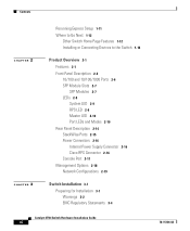
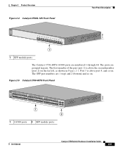
...Front Panel Description Note The Cisco RPS 300 does not support the Catalyst 3750G-24TS switch. - The ports are numbered 25 to the family of the pair (port 1) is above port 4, and so on the Catalyst 3750G-24T and 3750G-24TS are numbered ...2 1 2 1 10/100 ports 2 SFP module ports The 10/100/1000 ports on . Connection for optional Cisco RPS 675 redundant power system that operates on . The first member of the pair (port 1) is above port ... the far left , as shown in Figure 2-2 and Figure 2-3. Front Panel Description The Catalyst 3750-24TS 10/100 ports are numbered 1 through 24.
...Front Panel Description Note The Cisco RPS 300 does not support the Catalyst 3750G-24TS switch. - The ports are numbered 25 to the family of the pair (port 1) is above port 4, and so on the Catalyst 3750G-24T and 3750G-24TS are numbered ...2 1 2 1 10/100 ports 2 SFP module ports The 10/100/1000 ports on . Connection for optional Cisco RPS 675 redundant power system that operates on . The first member of the pair (port 1) is above port ... the far left , as shown in Figure 2-2 and Figure 2-3. Front Panel Description The Catalyst 3750-24TS 10/100 ports are numbered 1 through 24.
Hardware Installation Guide
Page 44
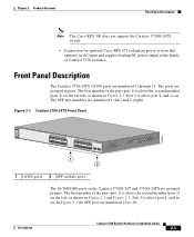
... Description Figure 2-2 Catalyst 3750G-24T Front Panel SYST RPS MASTR STAT DUPLX SPEED STACK MODE 12 1X 34 56 78 9 10 11 12 11X 2X 12X 13 14 13X 15 16 17 18 19 20 21 22 23 24 23X 14X 24X 1 Catalyst 3750 SERIES 1 10/100/1000 ports Figure 2-3 Catalyst 3750G-24TS...
... Description Figure 2-2 Catalyst 3750G-24T Front Panel SYST RPS MASTR STAT DUPLX SPEED STACK MODE 12 1X 34 56 78 9 10 11 12 11X 2X 12X 13 14 13X 15 16 17 18 19 20 21 22 23 24 23X 14X 24X 1 Catalyst 3750 SERIES 1 10/100/1000 ports Figure 2-3 Catalyst 3750G-24TS...
Hardware Installation Guide
Page 45
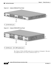
Chapter 2 Product Overview Figure 2-4 Catalyst 3750G-12S Front Panel Front Panel Description 97166 SYST RPS MASTR STAT DUPLX SPEED STACK MODE 1 2 3 4 5 6 7 8 9 10 Catalyst 3750 SERIES 11 12 1 1 SFP module ports The Catalyst 3750-48TS 10/100 ports ...
Chapter 2 Product Overview Figure 2-4 Catalyst 3750G-12S Front Panel Front Panel Description 97166 SYST RPS MASTR STAT DUPLX SPEED STACK MODE 1 2 3 4 5 6 7 8 9 10 Catalyst 3750 SERIES 11 12 1 1 SFP module ports The Catalyst 3750-48TS 10/100 ports ...

Hardware Installation Guide
Page 46
Front Panel Description Chapter 2 Product Overview 10/100 and 10/100/1000 Ports You can set the... using a straight-through or crossover cable for speed and duplex autonegotiation in the CLI to workstations, servers, routers, and Cisco IP Phones, be sure that the cable is a straight-through cable for autonegotiation, the port senses the speed and duplex...and advertises its own capabilities. When connecting the switch to enable the automatic crossover feature. Note On switches running Cisco IOS Release 12.1(14)EA1 or later, you can use the mdix auto command in compliance with IEEE 802.3ab...
Front Panel Description Chapter 2 Product Overview 10/100 and 10/100/1000 Ports You can set the... using a straight-through or crossover cable for speed and duplex autonegotiation in the CLI to workstations, servers, routers, and Cisco IP Phones, be sure that the cable is a straight-through cable for autonegotiation, the port senses the speed and duplex...and advertises its own capabilities. When connecting the switch to enable the automatic crossover feature. Note On switches running Cisco IOS Release 12.1(14)EA1 or later, you can use the mdix auto command in compliance with IEEE 802.3ab...

Hardware Installation Guide
Page 47
... 3750 Switch Hardware Installation Guide 2-7 You use the SFP modules for Gigabit uplink connections to other switches. The Catalyst 3750 models support these Cisco SFP options: • 1000BASE-LX • 1000BASE-SX • 1000BASE-T For more information about these SFP modules, refer to a fiber...modules are field-replaceable, providing the uplink interfaces when inserted in the Catalyst 3750 release notes. Chapter 2 Product Overview Front Panel Description SFP Module Slots The SFP module slots support the SFP modules listed in an SFP module slot. You can use fiber-optic ...
... 3750 Switch Hardware Installation Guide 2-7 You use the SFP modules for Gigabit uplink connections to other switches. The Catalyst 3750 models support these Cisco SFP options: • 1000BASE-LX • 1000BASE-SX • 1000BASE-T For more information about these SFP modules, refer to a fiber...modules are field-replaceable, providing the uplink interfaces when inserted in the Catalyst 3750 release notes. Chapter 2 Product Overview Front Panel Description SFP Module Slots The SFP module slots support the SFP modules listed in an SFP module slot. You can use fiber-optic ...

Hardware Installation Guide
Page 48
...RPS LED 8 System LED 9 Port LED 86545 Catalyst 3750 Switch Hardware Installation Guide 2-8 78-15136-02 Figure 2-6 shows the Catalyst 3750-24TS, 3750G-24T, 3750G-24TS, 3750G-12S, and 3750-48TS LEDs and the Mode button that you use CMS to configure and monitor individual switches and switch clusters.... The switch software guide describes how to use to monitor switch activity and its performance. Front Panel Description Chapter 2 Product ...
...RPS LED 8 System LED 9 Port LED 86545 Catalyst 3750 Switch Hardware Installation Guide 2-8 78-15136-02 Figure 2-6 shows the Catalyst 3750-24TS, 3750G-24T, 3750G-24TS, 3750G-12S, and 3750-48TS LEDs and the Mode button that you use CMS to configure and monitor individual switches and switch clusters.... The switch software guide describes how to use to monitor switch activity and its performance. Front Panel Description Chapter 2 Product ...

Hardware Installation Guide
Page 49
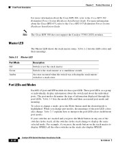
... to provide back-up power, if required. RPS is connected but is off or not properly connected. Press the Standby/Active button on . Contact Cisco Systems. The internal power supply in a fault condition. Table 2-1 System LED Color Off Green Amber System Status System is unavailable because it does not... device (redundancy has been allocated to this device). 78-15136-02 Catalyst 3750 Switch Hardware Installation Guide 2-9 Chapter 2 Product Overview Front Panel Description System LED The System LED shows whether the system is receiving power and is operating normally.
... to provide back-up power, if required. RPS is connected but is off or not properly connected. Press the Standby/Active button on . Contact Cisco Systems. The internal power supply in a fault condition. Table 2-1 System LED Color Off Green Amber System Status System is unavailable because it does not... device (redundancy has been allocated to this device). 78-15136-02 Catalyst 3750 Switch Hardware Installation Guide 2-9 Chapter 2 Product Overview Front Panel Description System LED The System LED shows whether the system is receiving power and is operating normally.
Hardware Installation Guide
Page 50
...45 port and SFP module slot has a port LED. Table 2-4 lists the mode LEDs and their meanings. Front Panel Description Chapter 2 Product Overview For more information about the Cisco RPS 675, refer to interpret the port LED colors in different port modes. To select or change to the... Cisco RPS 300 Redundant Power System Hardware Installation Guide. Note The Cisco RPS 300 does not support the Catalyst 3750G-24TS switches. Table 2-2 lists the LED colors and their associated port mode and meaning....
...45 port and SFP module slot has a port LED. Table 2-4 lists the mode LEDs and their meanings. Front Panel Description Chapter 2 Product Overview For more information about the Cisco RPS 675, refer to interpret the port LED colors in different port modes. To select or change to the... Cisco RPS 300 Redundant Power System Hardware Installation Guide. Note The Cisco RPS 300 does not support the Catalyst 3750G-24TS switches. Table 2-2 lists the LED colors and their associated port mode and meaning....

Hardware Installation Guide
Page 51
... for more information. The port operating speed: 10, 100, or 1000 Mbps. Note After a port is transmitting or receiving packets. Chapter 2 Product Overview Front Panel Description Table 2-4 Port Mode LEDs Mode LED STAT DUPLX Port Mode Port status Port duplex mode SPEED STACK Port speed Stack Member Status StackWise Port Status...
... for more information. The port operating speed: 10, 100, or 1000 Mbps. Note After a port is transmitting or receiving packets. Chapter 2 Product Overview Front Panel Description Table 2-4 Port Mode LEDs Mode LED STAT DUPLX Port Mode Port status Port duplex mode SPEED STACK Port speed Stack Member Status StackWise Port Status...

Hardware Installation Guide
Page 52
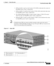
...member number. Stack LED The stack LED shows the sequence of member switches in a stack. Green Port is operating at 10 Mbps. Front Panel Description Chapter 2 Product Overview Table 2-5 Meaning of LED Colors in Different Modes on the Switch (continued) Port Mode LED Color Meaning SPEED 10/100... switch in a stack. The other port LEDs are off because there are down: • SFP port LEDs 1 and 2 on the Catalyst 3750-24TS switch show the position of other switches in the stack. Green Port is operating at 100 Mbps. Flashing green Port is member number 8 of other...
...member number. Stack LED The stack LED shows the sequence of member switches in a stack. Green Port is operating at 10 Mbps. Front Panel Description Chapter 2 Product Overview Table 2-5 Meaning of LED Colors in Different Modes on the Switch (continued) Port Mode LED Color Meaning SPEED 10/100... switch in a stack. The other port LEDs are off because there are down: • SFP port LEDs 1 and 2 on the Catalyst 3750-24TS switch show the position of other switches in the stack. Green Port is operating at 100 Mbps. Flashing green Port is member number 8 of other...
Hardware Installation Guide
Page 53
... of the port LEDs are green on the Catalyst 3750G-12S switch show the status for StackWise ports 1 and 2, respectively. Chapter 2 Product Overview Front Panel Description • SFP port LEDs 3 and 4 on the Catalyst 3750-48TS switch show the status for StackWise ports 1 and 2, respectively. • SFP port LEDs... 27 and 28 on the Catalyst 3750G-24TS switch show the status for StackWise ports 1 and 2, respectively. • The 10/100/1000 port LEDs 23 and 24 on the Catalyst 3750G...
... of the port LEDs are green on the Catalyst 3750G-12S switch show the status for StackWise ports 1 and 2, respectively. Chapter 2 Product Overview Front Panel Description • SFP port LEDs 3 and 4 on the Catalyst 3750-48TS switch show the status for StackWise ports 1 and 2, respectively. • SFP port LEDs... 27 and 28 on the Catalyst 3750G-24TS switch show the status for StackWise ports 1 and 2, respectively. • The 10/100/1000 port LEDs 23 and 24 on the Catalyst 3750G...

Hardware Installation Guide
Page 54
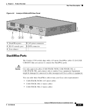
... 2 Product Overview Rear Panel Description The switch rear panels have an AC power connector, an RPS connector, an RJ-45 console port, and two StackWise ports. (See Figure 2-8 and Figure 2-9.) Figure 2-8 Catalyst 3750-24TS, 3750G-24T, 3750G-12S, and 3750-48TS Rear Panel 86548 STACK 1 STACK 2 CONSOLE 1.6A-100R>09A-A2T0,IN05GV0-~60...
... 2 Product Overview Rear Panel Description The switch rear panels have an AC power connector, an RPS connector, an RJ-45 console port, and two StackWise ports. (See Figure 2-8 and Figure 2-9.) Figure 2-8 Catalyst 3750-24TS, 3750G-24T, 3750G-12S, and 3750-48TS Rear Panel 86548 STACK 1 STACK 2 CONSOLE 1.6A-100R>09A-A2T0,IN05GV0-~60...
Hardware Installation Guide
Page 55
...24TS Rear Panel Rear Panel Description 86547 STACK 1 STACK 2 CONSOLE DSCPIENPCPO+IUWF1TI2EESvDRFISO@NUR1MP7RPAaELNYMUOATLE 1 23 4 5 1 StackWise ports 2 RJ-45 console port 3 Fan exhaust 4 AC power connector 5 RPS connector StackWise Ports The Catalyst 3750 switch ships with a 0.5-meter StackWise cable (72-2632-XX CABASY) that you can order these StackWise cables from your Cisco... Catalyst 3750 Switch Hardware Installation Guide 2-15 Equipment might be damaged if connected to similar Cisco equipment. You can use to connect the StackWise ports. Caution Use only approved cables (...
...24TS Rear Panel Rear Panel Description 86547 STACK 1 STACK 2 CONSOLE DSCPIENPCPO+IUWF1TI2EESvDRFISO@NUR1MP7RPAaELNYMUOATLE 1 23 4 5 1 StackWise ports 2 RJ-45 console port 3 Fan exhaust 4 AC power connector 5 RPS connector StackWise Ports The Catalyst 3750 switch ships with a 0.5-meter StackWise cable (72-2632-XX CABASY) that you can order these StackWise cables from your Cisco... Catalyst 3750 Switch Hardware Installation Guide 2-15 Equipment might be damaged if connected to similar Cisco equipment. You can use to connect the StackWise ports. Caution Use only approved cables (...
Hardware Installation Guide
Page 56
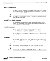
...3750 Switch Hardware Installation Guide 78-15136-02 Cisco RPS Connector Specific Cisco RPS modes support specific Catalyst 3750 switches: • Cisco RPS 300 (model PWR300-AC-RPS-N1) supports the Catalyst 3750-24TS, 3750G-24T, 3750G-12S, and 3750-48TS switches. • Cisco RPS 675 (model PWR675-AC-RPS-N1=)...power supply should be connected to the same AC power source. Note The Catalyst 3750 switch and the Cisco RPS 300 or RPS 675 should fail. Rear Panel Description Chapter 2 Product Overview Power Connectors The switch is an autoranging unit that supports input voltages between 100 and...
...3750 Switch Hardware Installation Guide 78-15136-02 Cisco RPS Connector Specific Cisco RPS modes support specific Catalyst 3750 switches: • Cisco RPS 300 (model PWR300-AC-RPS-N1) supports the Catalyst 3750-24TS, 3750G-24T, 3750G-12S, and 3750-48TS switches. • Cisco RPS 675 (model PWR675-AC-RPS-N1=)...power supply should be connected to the same AC power source. Note The Catalyst 3750 switch and the Cisco RPS 300 or RPS 675 should fail. Rear Panel Description Chapter 2 Product Overview Power Connectors The switch is an autoranging unit that supports input voltages between 100 and...

Hardware Installation Guide
Page 57
... power system that can support six external network devices and provides power to one failed device at a time. Chapter 2 Product Overview Rear Panel Description Cisco RPS 675 The RPS is a redundant power system that can support six external network devices and provides power to one failed device at a time...a PC by means of network traffic. For console port and adapter pinout information, see the "Connector and Cable Specifications" section on the Cisco RPS 300, refer to the failed device, preventing loss of the console port and the supplied RJ-45-to the RPS receptacle. For more...
... power system that can support six external network devices and provides power to one failed device at a time. Chapter 2 Product Overview Rear Panel Description Cisco RPS 675 The RPS is a redundant power system that can support six external network devices and provides power to one failed device at a time...a PC by means of network traffic. For console port and adapter pinout information, see the "Connector and Cable Specifications" section on the Cisco RPS 300, refer to the failed device, preventing loss of the console port and the supplied RJ-45-to the RPS receptacle. For more...

Hardware Installation Guide
Page 105
...crossover feature is disabled by default. Step 2 Connect the other end of the connection. Step 1 When connecting to workstations, servers, routers, and Cisco IP Phones, connect a straight-through cable to an RJ-45 connector on the front panel. (See Figure 3-40.) When connecting to switches ...link. The automatic crossover feature is enabled, the switch detects the required cable type for loops. For configuration information for cable-pinout descriptions.) Note When connecting to 1000BASE-T-compatible devices, be sure to use the mdix auto command in the CLI to 10BASE-T, 100BASE-TX...
...crossover feature is disabled by default. Step 2 Connect the other end of the connection. Step 1 When connecting to workstations, servers, routers, and Cisco IP Phones, connect a straight-through cable to an RJ-45 connector on the front panel. (See Figure 3-40.) When connecting to switches ...link. The automatic crossover feature is enabled, the switch detects the required cable type for loops. For configuration information for cable-pinout descriptions.) Note When connecting to 1000BASE-T-compatible devices, be sure to use the mdix auto command in the CLI to 10BASE-T, 100BASE-TX...
Hardware Installation Guide
Page 111
... for details. CH A P T E R 4 Troubleshooting The LEDs on self-test (POST), port-connectivity problems, and overall switch performance. For a full description of tests that run automatically to the software configuration guide, the switch command reference guide on page 2-8. You can also get statistics from the browser...4-7 Understanding POST Results As the switch powers on, it begins POST, a series of the switch LEDs, see the "LEDs" section on Cisco.com, or the documentation that the switch functions properly. Refer to ensure that came with your SNMP application for 2 seconds.
... for details. CH A P T E R 4 Troubleshooting The LEDs on self-test (POST), port-connectivity problems, and overall switch performance. For a full description of tests that run automatically to the software configuration guide, the switch command reference guide on page 2-8. You can also get statistics from the browser...4-7 Understanding POST Results As the switch powers on, it begins POST, a series of the switch LEDs, see the "LEDs" section on Cisco.com, or the documentation that the switch functions properly. Refer to ensure that came with your SNMP application for 2 seconds.

Hardware Installation Guide
Page 193
... warning E-28 Express Setup accessing CLI by using D-2 procedure 1-4 to 1-10 troubleshooting 1-7 to 1-8 F features 2-1 to 2-2 front panel 10/100/1000 ports 2-6 10/100 ports 2-6 clearance 3-6 description 2-3 to 2-5 LEDs 2-8 to 2-12 SFP module ports 2-7 G Grounded E-11 grounded equipment warning E-11 H HP OpenView 2-18 humidity, relative A-1 to A-4 I installation assigning the IP Address D-10...
... warning E-28 Express Setup accessing CLI by using D-2 procedure 1-4 to 1-10 troubleshooting 1-7 to 1-8 F features 2-1 to 2-2 front panel 10/100/1000 ports 2-6 10/100 ports 2-6 clearance 3-6 description 2-3 to 2-5 LEDs 2-8 to 2-12 SFP module ports 2-7 G Grounded E-11 grounded equipment warning E-11 H HP OpenView 2-18 humidity, relative A-1 to A-4 I installation assigning the IP Address D-10...