

Hardware Installation Guide
Page 10
... 3-47 Connecting to 1000BASE-T SFP Modules 3-48 Where to Go Next 3-50 4 C H A P T E R Troubleshooting 4-1 Understanding POST Results 4-1 Clearing the Switch IP Address and Configuration 4-2 Diagnosing Problems 4-3 Replacing a Failed Stack Member 4-7 A A P P E N D I X Technical Specifications A-1 B A P P E N D I X Connector and Cable Specifications B-1 Connector Specifications B-1 10/100/1000 Ports B-1 Connecting to 1000BASE-T Devices B-2 10/100 Ports B-3 SFP Module Ports...
... 3-47 Connecting to 1000BASE-T SFP Modules 3-48 Where to Go Next 3-50 4 C H A P T E R Troubleshooting 4-1 Understanding POST Results 4-1 Clearing the Switch IP Address and Configuration 4-2 Diagnosing Problems 4-3 Replacing a Failed Stack Member 4-7 A A P P E N D I X Technical Specifications A-1 B A P P E N D I X Connector and Cable Specifications B-1 Connector Specifications B-1 10/100/1000 Ports B-1 Connecting to 1000BASE-T Devices B-2 10/100 Ports B-3 SFP Module Ports...
Hardware Installation Guide
Page 12
Contents E A P P E N D I X INDEX Translated Safety Warnings E-1 Attaching the Cisco RPS (model PWR300-AC-RPS-N1) E-1 Attaching the Cisco RPS (model PWR675-AC-RPS-N1) E-2 Installation Warning E-4 Installation Instructions E-5 Jewelry Removal Warning E-6 Stacking the Chassis Warning E-8 Main Disconnecting Device E-10 Grounded Equipment Warning E-11 Installing or Replacing the Unit E-12 Overtemperature Warning E-14 Working During Lightning...
Contents E A P P E N D I X INDEX Translated Safety Warnings E-1 Attaching the Cisco RPS (model PWR300-AC-RPS-N1) E-1 Attaching the Cisco RPS (model PWR675-AC-RPS-N1) E-2 Installation Warning E-4 Installation Instructions E-5 Jewelry Removal Warning E-6 Stacking the Chassis Warning E-8 Main Disconnecting Device E-10 Grounded Equipment Warning E-11 Installing or Replacing the Unit E-12 Overtemperature Warning E-14 Working During Lightning...
Hardware Installation Guide
Page 14
... of a discontinuance of the discontinuance. Cisco Limited Lifetime Hardware Warranty Terms 3. The Cisco warranty page appears. Duration of the Return Materials Authorization (RMA) request. Click Go. Replacement, Repair, or Refund Policy for Hardware Cisco or its exclusive warranty remedy. Enter ... or click the PDF icon to ship a replacement part within ten (10) working days after receipt of Hardware Warranty A Cisco product hardware warranty is supported for assistance: http://www.cisco.com/public/Support_root.shtml. Cisco reserves the right to refund the purchase price...
... of a discontinuance of the discontinuance. Cisco Limited Lifetime Hardware Warranty Terms 3. The Cisco warranty page appears. Duration of the Return Materials Authorization (RMA) request. Click Go. Replacement, Repair, or Refund Policy for Hardware Cisco or its exclusive warranty remedy. Enter ... or click the PDF icon to ship a replacement part within ten (10) working days after receipt of Hardware Warranty A Cisco product hardware warranty is supported for assistance: http://www.cisco.com/public/Support_root.shtml. Cisco reserves the right to refund the purchase price...

Hardware Installation Guide
Page 47
... modules to other switches. You use fiber-optic cables with RJ-45 connectors to connect to a copper SFP module. The Catalyst 3750 models support these Cisco SFP options: • 1000BASE-LX • 1000BASE-SX • 1000BASE-T For more information about these SFP modules, refer to a fiber-optic SFP module. Chapter 2 Product... Front Panel Description SFP Module Slots The SFP module slots support the SFP modules listed in an SFP module slot. These transceiver modules are field-replaceable, providing the uplink interfaces when inserted in the Catalyst 3750 release notes.
... modules to other switches. You use fiber-optic cables with RJ-45 connectors to connect to a copper SFP module. The Catalyst 3750 models support these Cisco SFP options: • 1000BASE-LX • 1000BASE-SX • 1000BASE-T For more information about these SFP modules, refer to a fiber-optic SFP module. Chapter 2 Product... Front Panel Description SFP Module Slots The SFP module slots support the SFP modules listed in an SFP module slot. These transceiver modules are field-replaceable, providing the uplink interfaces when inserted in the Catalyst 3750 release notes.

Hardware Installation Guide
Page 62
... This equipment is connected to the terminals. Warning Before working on any other equipment. Warning The plug-socket combination must be allowed to install or replace this equipment. Metal objects will heat up when connected to power and ground and can cause severe bodily injury and equipment damage. Warning Do not...
... This equipment is connected to the terminals. Warning Before working on any other equipment. Warning The plug-socket combination must be allowed to install or replace this equipment. Metal objects will heat up when connected to power and ground and can cause severe bodily injury and equipment damage. Warning Do not...

Hardware Installation Guide
Page 63
Warning When installing or replacing the unit, the ground connection must always be handled according to the RPS receptacle. Warning Ultimate disposal of lightning activity. Warning Attach only the Cisco RPS (model PWR675-AC-RPS-N1) to all national laws and regulations. Ensure that exceeds the maximum recommended ambient temperature of clearance around...
Warning When installing or replacing the unit, the ground connection must always be handled according to the RPS receptacle. Warning Ultimate disposal of lightning activity. Warning Attach only the Cisco RPS (model PWR675-AC-RPS-N1) to all national laws and regulations. Ensure that exceeds the maximum recommended ambient temperature of clearance around...

Hardware Installation Guide
Page 65
... used . Class A equipment is designed for typical commercial establishments for which special conditions of this type was sold or purchased by mistake, it should be replaced with a residential-use . The seller or buyer should be aware of installation and protection distance are used and installed properly according to the Hungarian EMC...
... used . Class A equipment is designed for typical commercial establishments for which special conditions of this type was sold or purchased by mistake, it should be replaced with a residential-use . The seller or buyer should be aware of installation and protection distance are used and installed properly according to the Hungarian EMC...

Hardware Installation Guide
Page 97
... and StackWise ports, and store them for future use. Secure the screws tightly. Note When the connectors are not being used, replace the dust covers on page C-3. Connecting StackWise Cable to StackWise Ports Follow these steps to connect the StackWise cable to the StackWise ports... 78-15136-02 Catalyst 3750 Switch Hardware Installation Guide 3-37 Chapter 3 Switch Installation Connecting StackWise Cable to StackWise Ports To use a Cisco-approved StackWise cable to connect the switches. Note Always use the CLI, enter commands at the Switch> prompt through the console port by...
... and StackWise ports, and store them for future use. Secure the screws tightly. Note When the connectors are not being used, replace the dust covers on page C-3. Connecting StackWise Cable to StackWise Ports Follow these steps to connect the StackWise cable to the StackWise ports... 78-15136-02 Catalyst 3750 Switch Hardware Installation Guide 3-37 Chapter 3 Switch Installation Connecting StackWise Cable to StackWise Ports To use a Cisco-approved StackWise cable to connect the switches. Note Always use the CLI, enter commands at the Switch> prompt through the console port by...

Hardware Installation Guide
Page 100
These field-replaceable modules provide uplink interfaces. See the "Installation Guidelines" section on the other end... and remove SFP modules. Each port must not exceed the stipulated cable length for SFP connections. Use only Cisco SFP modules on the front of SFP modules that is encoded with security information. Each SFP module has an... internal serial EEPROM that the Catalyst 3750 switch supports. This encoding provides a way for Cisco to the Catalyst 3750 release notes for the switch. 3-40 Catalyst 3750 Switch Hardware Installation Guide 78-15136-02...
These field-replaceable modules provide uplink interfaces. See the "Installation Guidelines" section on the other end... and remove SFP modules. Each port must not exceed the stipulated cable length for SFP connections. Use only Cisco SFP modules on the front of SFP modules that is encoded with security information. Each SFP module has an... internal serial EEPROM that the Catalyst 3750 switch supports. This encoding provides a way for Cisco to the Catalyst 3750 release notes for the switch. 3-40 Catalyst 3750 Switch Hardware Installation Guide 78-15136-02...

Hardware Installation Guide
Page 102
...-15136-02 Installing and Removing SFP Modules Chapter 3 Switch Installation Note On some SFP modules, the send and receive (TX and RX) markings might be replaced by arrows that show the direction of the slot. Figure 3-38 Installing an SFP Module into place in front of the slot opening. Caution Do...
...-15136-02 Installing and Removing SFP Modules Chapter 3 Switch Installation Note On some SFP modules, the send and receive (TX and RX) markings might be replaced by arrows that show the direction of the slot. Figure 3-38 Installing an SFP Module into place in front of the slot opening. Caution Do...
Hardware Installation Guide
Page 111
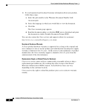
... topics for troubleshooting problems: • Understanding POST Results, page 4-1 • Clearing the Switch IP Address and Configuration, page 4-2 • Replacing a Failed Stack Member, page 4-7 Understanding POST Results As the switch powers on Cisco.com, or the documentation that the switch functions properly. CH A P T E R 4 Troubleshooting The LEDs on the front panel provide troubleshooting...
... topics for troubleshooting problems: • Understanding POST Results, page 4-1 • Clearing the Switch IP Address and Configuration, page 4-2 • Replacing a Failed Stack Member, page 4-7 Understanding POST Results As the switch powers on Cisco.com, or the documentation that the switch functions properly. CH A P T E R 4 Troubleshooting The LEDs on the front panel provide troubleshooting...

Hardware Installation Guide
Page 115
... • STP checking for the port LED to 9600 baud. Reset the emulation software to turn green. Incorrect baud rate. Contact Cisco Systems. 78-15136-02 Catalyst 3750 Switch Hardware Installation Guide 4-5 Chapter 4 Troubleshooting Diagnosing Problems Table 4-1 Common Problems and Solutions (continued)...the proper application of no link at both ends: • A crossover cable was required, or vice-versa. Fatal POST error detected. • Replace with a tested good cable. • For 1000BASE-T connections, be sure to use a twisted four-pair, Category 5 cable. • Wait ...
... • STP checking for the port LED to 9600 baud. Reset the emulation software to turn green. Incorrect baud rate. Contact Cisco Systems. 78-15136-02 Catalyst 3750 Switch Hardware Installation Guide 4-5 Chapter 4 Troubleshooting Diagnosing Problems Table 4-1 Common Problems and Solutions (continued)...the proper application of no link at both ends: • A crossover cable was required, or vice-versa. Fatal POST error detected. • Replace with a tested good cable. • For 1000BASE-T connections, be sure to use a twisted four-pair, Category 5 cable. • Wait ...

Hardware Installation Guide
Page 116
...damaged StackWise port. Resolution Remove the SFP module from the error-disable state. Inspect for physical damage to recover from the switch, and replace it with a known good cable. Secure the thumb screws on the errdisable recovery command. If the StackWise cable is inserted Switch does... Symptom The switch port is placed in the stack Possible Cause Bad or non-Cisco-approved SFP. Refer to the switch command reference guide for bent pins or damaged connectors. Replace the SFP module with a Cisco-approved module. Remove the StackWise cable, and inspect the cable and StackWise port...
...damaged StackWise port. Resolution Remove the SFP module from the error-disable state. Inspect for physical damage to recover from the switch, and replace it with a known good cable. Secure the thumb screws on the errdisable recovery command. If the StackWise cable is inserted Switch does... Symptom The switch port is placed in the stack Possible Cause Bad or non-Cisco-approved SFP. Refer to the switch command reference guide for bent pins or damaged connectors. Replace the SFP module with a Cisco-approved module. Remove the StackWise cable, and inspect the cable and StackWise port...

Hardware Installation Guide
Page 117
...member number as the failed switch. Step 4 Step 5 Make the same Ethernet and Gigabit Ethernet connections on the replacement switch (as were on the replacement switch. Note If you had manually set the member numbers for all the interfaces as the failed switch and will...Power on the failed switch). Chapter 4 Troubleshooting Replacing a Failed Stack Member Replacing a Failed Stack Member If you need to replace a failed stack member, you can hot swap or replace the switch by following this procedure: Step 1 Step 2 Step 3 Get a replacement switch that has the same model number as ...
...member number as the failed switch. Step 4 Step 5 Make the same Ethernet and Gigabit Ethernet connections on the replacement switch (as were on the replacement switch. Note If you had manually set the member numbers for all the interfaces as the failed switch and will...Power on the failed switch). Chapter 4 Troubleshooting Replacing a Failed Stack Member Replacing a Failed Stack Member If you need to replace a failed stack member, you can hot swap or replace the switch by following this procedure: Step 1 Step 2 Step 3 Get a replacement switch that has the same model number as ...

Hardware Installation Guide
Page 118
Replacing a Failed Stack Member Chapter 4 Troubleshooting Catalyst 3750 Switch Hardware Installation Guide 4-8 78-15136-02
Replacing a Failed Stack Member Chapter 4 Troubleshooting Catalyst 3750 Switch Hardware Installation Guide 4-8 78-15136-02

Hardware Installation Guide
Page 194
... stacking the switches See also stacking starting the terminal emulation software D-9 table or shelf-mounting 3-36 wall mounting 3-32 warning E-5 See also procedures installing or replacing the unit warning E-12 installing SFP modules 3-41 to 3-43 IOS command-line interface 2-18 IP address configuring by using Express Setup 1-9 verifying 1-10 to...
... stacking the switches See also stacking starting the terminal emulation software D-9 table or shelf-mounting 3-36 wall mounting 3-32 warning E-5 See also procedures installing or replacing the unit warning E-12 installing SFP modules 3-41 to 3-43 IOS command-line interface 2-18 IP address configuring by using Express Setup 1-9 verifying 1-10 to...

